EP0182493A1 - Sprühscheibe für Spritztrockenvorrichtung - Google Patents
Sprühscheibe für Spritztrockenvorrichtung Download PDFInfo
- Publication number
- EP0182493A1 EP0182493A1 EP85307361A EP85307361A EP0182493A1 EP 0182493 A1 EP0182493 A1 EP 0182493A1 EP 85307361 A EP85307361 A EP 85307361A EP 85307361 A EP85307361 A EP 85307361A EP 0182493 A1 EP0182493 A1 EP 0182493A1
- Authority
- EP
- European Patent Office
- Prior art keywords
- wheel
- ducts
- supply chamber
- discharge slit
- liquid
- Prior art date
- Legal status (The legal status is an assumption and is not a legal conclusion. Google has not performed a legal analysis and makes no representation as to the accuracy of the status listed.)
- Granted
Links
Images
Classifications
-
- B—PERFORMING OPERATIONS; TRANSPORTING
- B05—SPRAYING OR ATOMISING IN GENERAL; APPLYING FLUENT MATERIALS TO SURFACES, IN GENERAL
- B05B—SPRAYING APPARATUS; ATOMISING APPARATUS; NOZZLES
- B05B3/00—Spraying or sprinkling apparatus with moving outlet elements or moving deflecting elements
- B05B3/02—Spraying or sprinkling apparatus with moving outlet elements or moving deflecting elements with rotating elements
- B05B3/10—Spraying or sprinkling apparatus with moving outlet elements or moving deflecting elements with rotating elements discharging over substantially the whole periphery of the rotating member
- B05B3/1007—Spraying or sprinkling apparatus with moving outlet elements or moving deflecting elements with rotating elements discharging over substantially the whole periphery of the rotating member characterised by the rotating member
- B05B3/1014—Spraying or sprinkling apparatus with moving outlet elements or moving deflecting elements with rotating elements discharging over substantially the whole periphery of the rotating member characterised by the rotating member with a spraying edge, e.g. like a cup or a bell
-
- B—PERFORMING OPERATIONS; TRANSPORTING
- B05—SPRAYING OR ATOMISING IN GENERAL; APPLYING FLUENT MATERIALS TO SURFACES, IN GENERAL
- B05B—SPRAYING APPARATUS; ATOMISING APPARATUS; NOZZLES
- B05B3/00—Spraying or sprinkling apparatus with moving outlet elements or moving deflecting elements
- B05B3/02—Spraying or sprinkling apparatus with moving outlet elements or moving deflecting elements with rotating elements
- B05B3/10—Spraying or sprinkling apparatus with moving outlet elements or moving deflecting elements with rotating elements discharging over substantially the whole periphery of the rotating member
- B05B3/1007—Spraying or sprinkling apparatus with moving outlet elements or moving deflecting elements with rotating elements discharging over substantially the whole periphery of the rotating member characterised by the rotating member
Definitions
- This invention relates to an atomizer wheel for use in a spray drying apparatus, comprising a hub to be connected with a drive means, an annular supply chamber for liquid to be atomized disposed internally around the hub, a wheel cover provided with a liquid inlet opening leading to the supply chamber, and a number of substantially radial ejection ducts extending from the liquid supply chamber to the external surface of the wheel.
- rotating atomizer wheels have a higher yield per atomizing member than nozzle atomizers and are capable of atomizing liquids having a larger solids content and viscosity.
- atomizer wheels possess, moreover, far larger tolerance to changes in solids content, viscosity and liquid flow, wheel atomization is usually preferred where possible.
- powder products produced by use of wheel atomization present certain properties that make them less appropriate for some purposes. This applies for instance to the flowing properties of the powder, i.e. the ease with which the powder flows out of or down through an aperture. This property is important in several industrial operations and moreover in connection with the use of powder in certain beverage vending machines in which a determined portion of powder shall be quickly dosed to be mixed with water.
- the object of the invention is to provide an atomizer wheel which, while fully preserving the advantages of wheel atomization, makes it possible to obtain powder products with considerably better flowing properties than hitherto possible with prior art atomizer wheels.
- an atomizer wheel according to the invention is characterized in that the ejection ducts have a length constituting a considerable part of the radius of the wheel and terminate in a downwardly open, annular discharge slit at a relatively short distance from an external wall connected with the wheel cover, the inner surface of said external wall facing said discharge slit forming an axial-symmetrical surface of revolution with a substantially rectilinear generatrix including an angle of not more than 15° with the axis of rotation, the angular spacing of the ejection ducts and the axial length of the inner surface of the external wall being chosen so as to enable the formation of a coherent liquid film on said inner surface at the orifice of the discharge slit.
- the considerable length of the radial ejection ducts ensures a very strong acceleration of the liquid to be atomized.
- a liquid particle subjected to a tangential velocity by the ejection duct will as a result of the centrifugal acceleration caused thereby, obtain a radial velocity which as a maximum may become equal to the tangential velocity corresponding to the position of the particle.
- the radial velocity obtained by the particle may be of the same order of magnitude as the circumferential tangential velocity of the wheel. After leaving the ejection ducts the liquid will spread into a film on the inner side of the external wall of the annular discharge slit.
- the wheel design according to the invention possesses the advantage that after having left the ejection ducts in which a considerable velocity is imparted to it, and while it is subjected to conversion from discrete partial flow in the individual ducts into a coherent film the liquid maintains substantially the relative speed achieved in relation to the wheel.
- the radial velocity in the ejection ducts is of the same order of magnitude as the circumferential velocity of the wheel.
- the radial velocity component will to a substantial degree be converted into an axial component during the spread of the liquid on the external wall of the annular discharge slit while the tangential component is being maintained or perhaps even increases.
- the liquid remains in a continuous film on the external wall of the annular discharge slit under the influence of a strong centrifugal field for such a long time that any air bubbles have enough time to be expelled.
- the liquid will leave the edge of the atomizer wheel as a conical surface with velocity components of the same order of magnitude in the tangential and in the axial direction. The latter property is advantageous in two ways.
- the atomization mechanism resembles the one known from nozzles, and the particular properties characteristic of powder prepared by nozzle atomization - most particularly the good flowing properties - have incidentally also been observed in powder prepared by tests using an atomizer wheel according to the invention.
- the form of the spray cloud produced by the atomizer wheel is almost like an acute cone in contradiction to the flat umbrella ordinarily observed with known atomizer wheels. This fact opens possibilities of using spray drying chambers with smaller diameter.
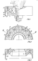
- FIG. 1 The embodiment of an atomizer wheel according to the invention illustrated in Fig. 1 includes a lower part 1 and an upper part 2 forming a wheel cover.
- the lower part 1 is designed with a hub 3 to be connected with a drive means not shown and comprises around the hub 3 an internal annular supply chamber 4 for the liquid to be atomized, said liquid being supplied through an annular slit 5 in a liquid distributor 6 extending into a central opening 7 in the cover.
- a number of ejection ducts extends towards the circumference of the wheel.
- the ducts 8 are formed in the underside of the wheel cover 2 and are separated as shown in Fig. 3 by downwardly extending intermediate pieces 9.
- the ejection ducts 8 have, in accordance with the invention, a length constituting a considerable portion of the total radius of the wheel, the length of the ejection ducts 8 being preferably larger than the radial extension of the liquid supply chamber 4.
- the ducts 8 terminate into a downwardly open annular discharge slit 10 whose internal surface is formed by the external surface of a protuberant edge portion 11 on the lower part 1 of the wheel around the annular chamber 4 while the external surface of the slit 10 is constituted by the inner side of a circumferential external wall extending downwardly from the wheel cover 2.
- the inner surface 13 of the external wall 12 constitutes an axial-symmetrical surface of revolution with a substantially linear generatrix including, according to the invention an angle of not more than 15° with the axis of revolution. In the illustrated embodiment said angle is about 9°.
- the number of ejection ducts 8 of which twenty-four are present in the illustrated embodiment and the axial extension of the inner surface 13 of the external wall 12 are dimensioned just with a view to formation of such a coherent liquid film.
- the steepness of the surface of revolution, in the illustrated embodiment a frusto-conical surface, created by the wall inner surface 13 causes the considerable, radial velocity component of the ejected_liquid at the outlets of the ducts to be converted into a substantially equally large, downwardly directed velocity component so that the total atomization from the tear-off edge 14 is effected in the form of a cone having an acute apical angle, in contrast with the comparatively flat umbrella-shaped spray cloud issuing from atomizer wheels having ejection apertures in the outside of the wheel.
- the atomization from the wheel resembles to a substantial degree nozzle atomization.while preserving the general advantages with respect to flexibility and reliability in operation associated with wheel atomization.
- said discharge slit 10 is curved at the upper side of the outlets of the ejection ducts 8.
- the inner side 15 facing the annular liquid supply chamber 4, of the protuberant edge portion 11 of the lower part 1 forms an outwardly upwards sloping bottom for all the ejection ducts 8.
- the axial extension of the inner wall surface 13 of the external wall 12 is dimensioned so that the liquid film formed on the wall inner surface remains so long thereon that air bubbles are expelled. This provides for obtaining an advantageous reduction of the amount of occluded air in the powder product produced by the spray drying.
- the external side of the protuberant edge portion 11 of the external surface of the lower part 1 has such a shape that the width of the discharge slit 10 increases in the direction towards the downwardly directed outlet of the slit. This eliminates substantially the risk of undesired deposits of dried solids at the outlet of the slit.
- the invention is not limited to the illustrated embodiment since the ejetion ducts as well as the discharge slit may have other shapes, provided the length of the ejection ducts constitutes a considerable portion of the radius of the wheel and the form of the external wall of the discharge slit is such that a coherent liquid film remaining for a comparatively long time in the centrifugal field is formed on the wall.
- the inner viall surface 13 may have another form than shown, for instance a cylinder surface or a downwardly diverging frusto-conical surface or a slightly curved surface, provided it has such a steepness that the above mentioned considerable axial velocity component is ensured at the atomization.
- An industrial spray drying plant consisting of a spray dryer with an associated vibrated fluid bed as afterdryer.
- Drying tests with skimmed milk concentrate were effected. Tests were carried out, first with a conventional atomizer wheel having a diameter of 210 mm and straight ejection ducts, and second with an atomizer wheel as illustrated on the drawing and with the same diameter, and the tests were further carried out under the same drying conditions.
- the flowability of the produced powder products was measured according to "Analytical Methods for Dry Milk Products", Fourth Edition, issued by A/S Niro Atomizer, Copenhagen (1978) Method No. A23a, according to which the flowability of a powder is determined in a standard apparatus as the time (in seconds) necessary for a given volume of the powder to leave a rotating drum through given slits.
- the flowability of the powder produced by using a conventional atomizer wheel was forty-one seconds, for the powder produced by the atomizer wheel according to the invention twenty-two seconds.
- the flowability was measured to forty-one seconds in tests with a conventional wheel and twenty-two seconds in tests with the wheel according to the invention, respectively.
- Example 2 In another spray drying plant of the same type as used in Example 1 and 2 drying tests with a fat milk concentrate containing 50% foreign fat were carried out. In this case the flowability was measured to eighty-two seconds for the powder produced in the tests with a conventional atomizer wheel and sixteen seconds for the powder produced in the tests with the wheel according to the invention.
Landscapes
- Vaporization, Distillation, Condensation, Sublimation, And Cold Traps (AREA)
- Nozzles (AREA)
- Drying Of Solid Materials (AREA)
- Nitrogen And Oxygen Or Sulfur-Condensed Heterocyclic Ring Systems (AREA)
- Nitrogen Condensed Heterocyclic Rings (AREA)
- Detergent Compositions (AREA)
Priority Applications (1)
| Application Number | Priority Date | Filing Date | Title |
|---|---|---|---|
| AT85307361T ATE40801T1 (de) | 1984-10-26 | 1985-10-14 | Spruehscheibe fuer spritztrockenvorrichtung. |
Applications Claiming Priority (2)
| Application Number | Priority Date | Filing Date | Title |
|---|---|---|---|
| DK512284A DK151198B (da) | 1984-10-26 | 1984-10-26 | Forstoeverhjul til brug i et forstoevningstoerringsanlaeg |
| DK5122/84 | 1984-10-26 |
Publications (2)
| Publication Number | Publication Date |
|---|---|
| EP0182493A1 true EP0182493A1 (de) | 1986-05-28 |
| EP0182493B1 EP0182493B1 (de) | 1989-02-15 |
Family
ID=8139631
Family Applications (1)
| Application Number | Title | Priority Date | Filing Date |
|---|---|---|---|
| EP85307361A Expired EP0182493B1 (de) | 1984-10-26 | 1985-10-14 | Sprühscheibe für Spritztrockenvorrichtung |
Country Status (10)
| Country | Link |
|---|---|
| US (1) | US4733821A (de) |
| EP (1) | EP0182493B1 (de) |
| JP (1) | JP2505407B2 (de) |
| AT (1) | ATE40801T1 (de) |
| AU (1) | AU581031B2 (de) |
| DE (1) | DE3568260D1 (de) |
| DK (1) | DK151198B (de) |
| ES (1) | ES8609683A1 (de) |
| FI (1) | FI82982C (de) |
| NZ (1) | NZ213924A (de) |
Cited By (3)
| Publication number | Priority date | Publication date | Assignee | Title |
|---|---|---|---|---|
| EP0387492A1 (de) * | 1989-03-16 | 1990-09-19 | Deutsche Solvay-Werke Gmbh | Verfahren zur Herstellung von Natriumaluminat |
| WO2001070410A1 (en) * | 2000-03-17 | 2001-09-27 | Jkj & Em Mahon Pty Ltd | Apparatus and method for applying liquid droplets to a particulate material |
| AU777985B2 (en) * | 2000-03-17 | 2004-11-11 | Jkj & Em Mahon Pty Ltd | Apparatus and method for applying liquid droplets to a particulate material |
Families Citing this family (9)
| Publication number | Priority date | Publication date | Assignee | Title |
|---|---|---|---|---|
| US5078321A (en) * | 1990-06-22 | 1992-01-07 | Nordson Corporation | Rotary atomizer cup |
| US5356075A (en) * | 1990-07-10 | 1994-10-18 | Apv Pasilac Anhydro As | Atomizer wheel with a divided wear ring |
| DK0538378T3 (da) * | 1990-07-10 | 1995-06-19 | Apv Anhydro A S Apv Pasilac A | Forstøverhjul |
| US20010048140A1 (en) | 1997-04-10 | 2001-12-06 | Inao Toyoda | Photo sensing integrated circuit device and related circuit adjustment |
| SE9904345D0 (sv) * | 1999-12-01 | 1999-12-01 | Ralf Goeran Andersson | method and device for producing a coherent layer of even thickness of liquid or melt on a rotating disk |
| DE10030497A1 (de) * | 2000-06-21 | 2002-01-03 | Turbo Lufttechnik Gmbh | Axialventilator mit reversierbarer Strömungsrichtung |
| KR20030046520A (ko) | 2000-11-06 | 2003-06-12 | 캐보트 코포레이션 | 개질된 산소 환원된 밸브 금속 산화물 |
| JP2006326393A (ja) * | 2005-05-23 | 2006-12-07 | Tdk Corp | 噴霧盤、噴霧装置及び噴霧乾燥機 |
| CN106662397B (zh) * | 2014-06-04 | 2020-06-12 | Gea工艺工程有限公司 | 用于喷雾干燥的空气扩散器和包括金属成形的制造空气扩散器的方法 |
Citations (3)
| Publication number | Priority date | Publication date | Assignee | Title |
|---|---|---|---|---|
| GB1311464A (en) * | 1968-12-03 | 1973-03-28 | Controsion Electrostatic Ltd | Spray guns |
| FR2336181A1 (fr) * | 1975-12-26 | 1977-07-22 | Marchand Bernard | Moteur pneumatique pour appareil d'application de peinture par procede electrostatique a tete atomisante rotative a grande vitesse |
| EP0034278A2 (de) * | 1980-02-15 | 1981-08-26 | BASF Lacke + Farben AG | Verfahren und Vorrichtung zum elektrostatischen Überziehen von Gegenständen mit einem Fluid |
Family Cites Families (8)
| Publication number | Priority date | Publication date | Assignee | Title |
|---|---|---|---|---|
| US1620625A (en) * | 1923-10-13 | 1927-03-15 | Joseph J Babka | Oil atomizer |
| US2515665A (en) * | 1946-09-11 | 1950-07-18 | American Dyewood Company | Spray drying device |
| DK86740C (da) * | 1956-09-10 | 1959-01-12 | Anhydro As | Forstøverhjul til brug ved forstøvningstørring af opløsninger eller suspensioner. |
| FR2412351A1 (fr) * | 1977-12-20 | 1979-07-20 | Air Ind | Projecteur electrostatique de peinture a bol ou a disque tournant avec un joint d'etancheite pneumatique |
| JPS56141867A (en) * | 1980-04-04 | 1981-11-05 | Toyota Motor Corp | Rotary atomizing electrostatic coating device |
| US4380321A (en) * | 1981-01-26 | 1983-04-19 | Binks Manufacturing Company | Color change valve structure for rotary head electrostatic spray coating systems |
| JPS5867368A (ja) * | 1981-10-16 | 1983-04-21 | Trinity Ind Corp | 静電塗装方法及びそれに用いる装置 |
| GB2131328B (en) * | 1982-12-10 | 1986-03-19 | Dresser Ind | Improvements in or relating to liquid spraying |
-
1984
- 1984-10-26 DK DK512284A patent/DK151198B/da not_active Application Discontinuation
-
1985
- 1985-10-14 DE DE8585307361T patent/DE3568260D1/de not_active Expired
- 1985-10-14 AT AT85307361T patent/ATE40801T1/de not_active IP Right Cessation
- 1985-10-14 EP EP85307361A patent/EP0182493B1/de not_active Expired
- 1985-10-21 US US06/789,909 patent/US4733821A/en not_active Expired - Fee Related
- 1985-10-22 NZ NZ213924A patent/NZ213924A/en unknown
- 1985-10-22 AU AU48948/85A patent/AU581031B2/en not_active Ceased
- 1985-10-22 FI FI854134A patent/FI82982C/fi not_active IP Right Cessation
- 1985-10-23 ES ES548134A patent/ES8609683A1/es not_active Expired
- 1985-10-25 JP JP60239275A patent/JP2505407B2/ja not_active Expired - Lifetime
Patent Citations (3)
| Publication number | Priority date | Publication date | Assignee | Title |
|---|---|---|---|---|
| GB1311464A (en) * | 1968-12-03 | 1973-03-28 | Controsion Electrostatic Ltd | Spray guns |
| FR2336181A1 (fr) * | 1975-12-26 | 1977-07-22 | Marchand Bernard | Moteur pneumatique pour appareil d'application de peinture par procede electrostatique a tete atomisante rotative a grande vitesse |
| EP0034278A2 (de) * | 1980-02-15 | 1981-08-26 | BASF Lacke + Farben AG | Verfahren und Vorrichtung zum elektrostatischen Überziehen von Gegenständen mit einem Fluid |
Cited By (3)
| Publication number | Priority date | Publication date | Assignee | Title |
|---|---|---|---|---|
| EP0387492A1 (de) * | 1989-03-16 | 1990-09-19 | Deutsche Solvay-Werke Gmbh | Verfahren zur Herstellung von Natriumaluminat |
| WO2001070410A1 (en) * | 2000-03-17 | 2001-09-27 | Jkj & Em Mahon Pty Ltd | Apparatus and method for applying liquid droplets to a particulate material |
| AU777985B2 (en) * | 2000-03-17 | 2004-11-11 | Jkj & Em Mahon Pty Ltd | Apparatus and method for applying liquid droplets to a particulate material |
Also Published As
| Publication number | Publication date |
|---|---|
| ATE40801T1 (de) | 1989-03-15 |
| DK151198B (da) | 1987-11-09 |
| FI82982C (fi) | 1991-05-10 |
| ES8609683A1 (es) | 1986-09-01 |
| US4733821A (en) | 1988-03-29 |
| JP2505407B2 (ja) | 1996-06-12 |
| AU581031B2 (en) | 1989-02-09 |
| DK512284D0 (da) | 1984-10-26 |
| AU4894885A (en) | 1986-05-01 |
| FI854134L (fi) | 1986-04-27 |
| JPS61111161A (ja) | 1986-05-29 |
| DE3568260D1 (en) | 1989-03-23 |
| NZ213924A (en) | 1986-12-05 |
| DK512284A (da) | 1986-04-27 |
| ES548134A0 (es) | 1986-09-01 |
| EP0182493B1 (de) | 1989-02-15 |
| FI82982B (fi) | 1991-01-31 |
| FI854134A0 (fi) | 1985-10-22 |
Similar Documents
| Publication | Publication Date | Title |
|---|---|---|
| US4405086A (en) | Device for atomizing liquid color | |
| EP0182493B1 (de) | Sprühscheibe für Spritztrockenvorrichtung | |
| US6338438B1 (en) | Process and a device for atomizing liquids | |
| US4684064A (en) | Centrifugal atomizer | |
| US8613400B2 (en) | Ultrasonic atomizing nozzle with cone-spray feature | |
| EP0034278B1 (de) | Verfahren und Vorrichtung zum elektrostatischen Überziehen von Gegenständen mit einem Fluid | |
| US4795095A (en) | Rotary atomizer | |
| CN101678374B (zh) | 具有抛物线状流动表面的喷涂装置 | |
| US9707578B2 (en) | Rotary atomizer nozzle head, and rotary atomizer with such a nozzle head | |
| KR890003447B1 (ko) | 공정가스 도입장치 | |
| US3346192A (en) | Atomizing apparatus | |
| US4303200A (en) | Atomizer wheel for the atomization of liquids | |
| US4581830A (en) | Apparatus for fluid-bed drying, particularly for simultaneous drying and disintegration of a material in the form of a paste | |
| US5137215A (en) | Centrifugal device for atomizing a coating product, particularly for application by electrostatic spraying | |
| US3250473A (en) | Atomizing method and apparatus | |
| US4512518A (en) | Atomizing head | |
| US4572100A (en) | Apparatus for moistening loose material | |
| EP0299059A1 (de) | Vorrichtung und verfahren zur aufbringung einer gleichmmässigen beschichtung auf nährmittel | |
| CA2221897A1 (en) | Liquid atomizing nozzle | |
| US2992778A (en) | Liquid spray apparatus | |
| SU976927A1 (ru) | Центробежный диск дл распыливани пищевых продуктов в сушильную камеру | |
| JPS594758Y2 (ja) | 噴霧装置の回転型霧化頭 | |
| JPH0612836Y2 (ja) | 回転霧化静電塗装装置 | |
| GB1582177A (en) | Spray apparatus | |
| JP2025179825A (ja) | 液体被覆製品用の噴霧ボウル、噴霧ボウルを備えた回転式噴霧器及び回転式噴霧器を用いて被覆製品を塗布する方法 |
Legal Events
| Date | Code | Title | Description |
|---|---|---|---|
| PUAI | Public reference made under article 153(3) epc to a published international application that has entered the european phase |
Free format text: ORIGINAL CODE: 0009012 |
|
| AK | Designated contracting states |
Kind code of ref document: A1 Designated state(s): AT BE CH DE FR GB IT LI NL SE |
|
| 17P | Request for examination filed |
Effective date: 19861125 |
|
| 17Q | First examination report despatched |
Effective date: 19870908 |
|
| GRAA | (expected) grant |
Free format text: ORIGINAL CODE: 0009210 |
|
| AK | Designated contracting states |
Kind code of ref document: B1 Designated state(s): AT BE CH DE FR GB IT LI NL SE |
|
| REF | Corresponds to: |
Ref document number: 40801 Country of ref document: AT Date of ref document: 19890315 Kind code of ref document: T |
|
| REF | Corresponds to: |
Ref document number: 3568260 Country of ref document: DE Date of ref document: 19890323 |
|
| ITF | It: translation for a ep patent filed | ||
| ET | Fr: translation filed | ||
| PLBE | No opposition filed within time limit |
Free format text: ORIGINAL CODE: 0009261 |
|
| STAA | Information on the status of an ep patent application or granted ep patent |
Free format text: STATUS: NO OPPOSITION FILED WITHIN TIME LIMIT |
|
| 26N | No opposition filed | ||
| ITTA | It: last paid annual fee | ||
| BECA | Be: change of holder's address |
Free format text: 931215 *NIRO HOLDING A/S:BREDGADE 6, 1260 COPENHAGEN K |
|
| BECH | Be: change of holder |
Free format text: 931215 *NIRO HOLDING A/S |
|
| REG | Reference to a national code |
Ref country code: CH Ref legal event code: PUE Owner name: NIRO HOLDING A/S |
|
| REG | Reference to a national code |
Ref country code: GB Ref legal event code: 732E |
|
| NLT1 | Nl: modifications of names registered in virtue of documents presented to the patent office pursuant to art. 16 a, paragraph 1 |
Owner name: NIRO A/S TE SOEBORG, DENEMARKEN. |
|
| REG | Reference to a national code |
Ref country code: FR Ref legal event code: TP Ref country code: FR Ref legal event code: CD |
|
| ITPR | It: changes in ownership of a european patent |
Owner name: CAMBIO RAGIONE SOCIALE;NIRO A/S |
|
| NLS | Nl: assignments of ep-patents |
Owner name: NIRO HOLDING A/S TE KOPENHAGEN, DENEMARKEN. |
|
| REG | Reference to a national code |
Ref country code: GB Ref legal event code: 746 Effective date: 19940523 |
|
| EAL | Se: european patent in force in sweden |
Ref document number: 85307361.7 |
|
| PGFP | Annual fee paid to national office [announced via postgrant information from national office to epo] |
Ref country code: SE Payment date: 19960916 Year of fee payment: 12 |
|
| PGFP | Annual fee paid to national office [announced via postgrant information from national office to epo] |
Ref country code: CH Payment date: 19960924 Year of fee payment: 12 |
|
| PGFP | Annual fee paid to national office [announced via postgrant information from national office to epo] |
Ref country code: AT Payment date: 19961007 Year of fee payment: 12 |
|
| PGFP | Annual fee paid to national office [announced via postgrant information from national office to epo] |
Ref country code: GB Payment date: 19961008 Year of fee payment: 12 |
|
| PGFP | Annual fee paid to national office [announced via postgrant information from national office to epo] |
Ref country code: BE Payment date: 19961011 Year of fee payment: 12 |
|
| PGFP | Annual fee paid to national office [announced via postgrant information from national office to epo] |
Ref country code: FR Payment date: 19961022 Year of fee payment: 12 |
|
| PGFP | Annual fee paid to national office [announced via postgrant information from national office to epo] |
Ref country code: NL Payment date: 19961031 Year of fee payment: 12 |
|
| PGFP | Annual fee paid to national office [announced via postgrant information from national office to epo] |
Ref country code: DE Payment date: 19961223 Year of fee payment: 12 |
|
| PG25 | Lapsed in a contracting state [announced via postgrant information from national office to epo] |
Ref country code: GB Free format text: LAPSE BECAUSE OF NON-PAYMENT OF DUE FEES Effective date: 19971014 Ref country code: AT Free format text: LAPSE BECAUSE OF NON-PAYMENT OF DUE FEES Effective date: 19971014 |
|
| PG25 | Lapsed in a contracting state [announced via postgrant information from national office to epo] |
Ref country code: SE Free format text: LAPSE BECAUSE OF NON-PAYMENT OF DUE FEES Effective date: 19971015 |
|
| PG25 | Lapsed in a contracting state [announced via postgrant information from national office to epo] |
Ref country code: LI Free format text: LAPSE BECAUSE OF NON-PAYMENT OF DUE FEES Effective date: 19971031 Ref country code: FR Free format text: THE PATENT HAS BEEN ANNULLED BY A DECISION OF A NATIONAL AUTHORITY Effective date: 19971031 Ref country code: CH Free format text: LAPSE BECAUSE OF NON-PAYMENT OF DUE FEES Effective date: 19971031 Ref country code: BE Free format text: LAPSE BECAUSE OF NON-PAYMENT OF DUE FEES Effective date: 19971031 |
|
| BERE | Be: lapsed |
Owner name: NIRO HOLDING A/S Effective date: 19971031 |
|
| PG25 | Lapsed in a contracting state [announced via postgrant information from national office to epo] |
Ref country code: NL Free format text: LAPSE BECAUSE OF NON-PAYMENT OF DUE FEES Effective date: 19980501 |
|
| GBPC | Gb: european patent ceased through non-payment of renewal fee |
Effective date: 19971014 |
|
| REG | Reference to a national code |
Ref country code: CH Ref legal event code: PL |
|
| NLV4 | Nl: lapsed or anulled due to non-payment of the annual fee |
Effective date: 19980501 |
|
| PG25 | Lapsed in a contracting state [announced via postgrant information from national office to epo] |
Ref country code: DE Free format text: LAPSE BECAUSE OF NON-PAYMENT OF DUE FEES Effective date: 19980701 |
|
| EUG | Se: european patent has lapsed |
Ref document number: 85307361.7 |
|
| REG | Reference to a national code |
Ref country code: FR Ref legal event code: ST |