EP0182498B1 - Verfahren und Vorrichtung zur Verhinderung einer Verunreinigung von Schwammhülsen in Kernbehältern - Google Patents
Verfahren und Vorrichtung zur Verhinderung einer Verunreinigung von Schwammhülsen in Kernbehältern Download PDFInfo
- Publication number
- EP0182498B1 EP0182498B1 EP85307454A EP85307454A EP0182498B1 EP 0182498 B1 EP0182498 B1 EP 0182498B1 EP 85307454 A EP85307454 A EP 85307454A EP 85307454 A EP85307454 A EP 85307454A EP 0182498 B1 EP0182498 B1 EP 0182498B1
- Authority
- EP
- European Patent Office
- Prior art keywords
- inner barrel
- core
- fluid
- container means
- receiving end
- Prior art date
- Legal status (The legal status is an assumption and is not a legal conclusion. Google has not performed a legal analysis and makes no representation as to the accuracy of the status listed.)
- Expired
Links
- 238000000034 method Methods 0.000 title claims description 13
- 238000011109 contamination Methods 0.000 title abstract 2
- 239000012530 fluid Substances 0.000 claims abstract description 79
- 238000005553 drilling Methods 0.000 claims abstract description 31
- 238000007789 sealing Methods 0.000 claims abstract description 14
- XLYOFNOQVPJJNP-UHFFFAOYSA-N water Substances O XLYOFNOQVPJJNP-UHFFFAOYSA-N 0.000 claims description 21
- 230000002745 absorbent Effects 0.000 claims description 16
- 239000002250 absorbent Substances 0.000 claims description 16
- 239000000463 material Substances 0.000 claims description 11
- 229920005830 Polyurethane Foam Polymers 0.000 claims description 10
- 239000011496 polyurethane foam Substances 0.000 claims description 10
- 238000006073 displacement reaction Methods 0.000 claims description 8
- 239000000356 contaminant Substances 0.000 claims description 6
- 238000011084 recovery Methods 0.000 claims description 4
- 239000007788 liquid Substances 0.000 claims description 3
- 238000012546 transfer Methods 0.000 abstract description 2
- 239000011162 core material Substances 0.000 description 113
- 241000243142 Porifera Species 0.000 description 67
- 235000012461 sponges Nutrition 0.000 description 67
- 239000007789 gas Substances 0.000 description 11
- 150000003839 salts Chemical class 0.000 description 6
- 230000006835 compression Effects 0.000 description 5
- 238000007906 compression Methods 0.000 description 5
- HZAXFHJVJLSVMW-UHFFFAOYSA-N 2-Aminoethan-1-ol Chemical group NCCO HZAXFHJVJLSVMW-UHFFFAOYSA-N 0.000 description 4
- 238000010521 absorption reaction Methods 0.000 description 3
- 239000012065 filter cake Substances 0.000 description 3
- 230000008569 process Effects 0.000 description 3
- 230000000740 bleeding effect Effects 0.000 description 2
- 238000004891 communication Methods 0.000 description 2
- 230000000694 effects Effects 0.000 description 2
- 238000000605 extraction Methods 0.000 description 2
- 239000006260 foam Substances 0.000 description 2
- 238000003780 insertion Methods 0.000 description 2
- 230000037431 insertion Effects 0.000 description 2
- 230000014759 maintenance of location Effects 0.000 description 2
- 238000005259 measurement Methods 0.000 description 2
- 230000035699 permeability Effects 0.000 description 2
- 230000004044 response Effects 0.000 description 2
- 239000000126 substance Substances 0.000 description 2
- 239000011358 absorbing material Substances 0.000 description 1
- 230000002378 acidificating effect Effects 0.000 description 1
- 230000004075 alteration Effects 0.000 description 1
- XAGFODPZIPBFFR-UHFFFAOYSA-N aluminium Chemical compound [Al] XAGFODPZIPBFFR-UHFFFAOYSA-N 0.000 description 1
- 229910052782 aluminium Inorganic materials 0.000 description 1
- 238000013459 approach Methods 0.000 description 1
- 230000015572 biosynthetic process Effects 0.000 description 1
- 150000001875 compounds Chemical class 0.000 description 1
- 238000010276 construction Methods 0.000 description 1
- 230000007423 decrease Effects 0.000 description 1
- 230000001419 dependent effect Effects 0.000 description 1
- 238000011161 development Methods 0.000 description 1
- 238000010586 diagram Methods 0.000 description 1
- 239000002283 diesel fuel Substances 0.000 description 1
- 239000013505 freshwater Substances 0.000 description 1
- 238000009533 lab test Methods 0.000 description 1
- 239000000314 lubricant Substances 0.000 description 1
- QSHDDOUJBYECFT-UHFFFAOYSA-N mercury Chemical compound [Hg] QSHDDOUJBYECFT-UHFFFAOYSA-N 0.000 description 1
- 229910052753 mercury Inorganic materials 0.000 description 1
- 230000000149 penetrating effect Effects 0.000 description 1
- 230000009467 reduction Effects 0.000 description 1
- 230000000717 retained effect Effects 0.000 description 1
- 229920006395 saturated elastomer Polymers 0.000 description 1
- 238000009738 saturating Methods 0.000 description 1
- 239000002689 soil Substances 0.000 description 1
- 238000006467 substitution reaction Methods 0.000 description 1
- 238000009736 wetting Methods 0.000 description 1
Images


Classifications
-
- E—FIXED CONSTRUCTIONS
- E21—EARTH OR ROCK DRILLING; MINING
- E21B—EARTH OR ROCK DRILLING; OBTAINING OIL, GAS, WATER, SOLUBLE OR MELTABLE MATERIALS OR A SLURRY OF MINERALS FROM WELLS
- E21B25/00—Apparatus for obtaining or removing undisturbed cores, e.g. core barrels or core extractors
- E21B25/08—Coating, freezing, consolidating cores; Recovering uncontaminated cores or cores at formation pressure
Definitions
- This invention pertains in general to an apparatus and to a method for well coring and, more particularly, to a well coring apparatus and a method utilizing an absorbent sponge for containing the subterranean fluid in the core.
- Sponge coring comprises disposing a high porosity sponge on the interior surface of the inner barrel of the well coring apparatus. The core is then forced into the inner barrel with the sponge disposed about the sides thereof. The oil and/or gas contained in the core then "bleeds" into the sponge thereby retaining an accurate profile of the oil along the longitudinal axis of the core.
- the present invention may be regarded as a development of the invention disclosed and claimed in EP-A-0,132,020.
- the present invention provides a well core drilling apparatus for recovery of subterranean fluid, comprising: means for boring a well core containing subterranean fluid; container means associated with said boring means for receiving said well core at one end and for containing said well core; said container means being sealed at the opposite end from said receiving end; an absorbent member disposed on the inner walls of said container means and positioned adjacent said well core, said absorbent member for absorbing subterranean fluid that bleeds from said well core; and a piston disposed in the receiving end of said container means for being displaced from the receiving end of the container means towards the opposite end of the container means by said core when said core enters said container means; characterised by means for sealing the space between said piston and the inner walls of said container means when said piston is disposed at the receiving end thereof, displacement of said piston from the receiving end of said container means towards the opposite end thereof breaking the seal; and a fluid
- the present invention also provides a method for drilling a well core and recovering subterranean fluids disposed therein, comprising: drilling the well core; providing an inner barrel in the well-coring apparatus for containing the well core, the inner barrel having a receiving end for receiving the well core as it is formed; disposing absorbing material in the inner barrel for absorbing the subterranean fluid that is contained in the well core for later retrieval and analysis; and sealing the end of the inner barrel opposite the receiving end thereof; and disposing a piston in the receiving end of the inner barrel, the piston being arranged to contact the well core and to be displaceable within the inner barrel from the receiving end towards the opposite end thereof as the well core moves upward into the inner barrel; characterised by sealing the space between the piston and the inner walls of the inner barrel at the receiving end thereof such that the receiving end of the inner barrel is sealed to provide a completely sealed inner barrel; disposing a pressurized fluid within the inner barrel to maintain the seal at the receiving end of the barrel; and breaking the seal at the receiving end of the inner
- FIG. 1 there is illustrated a cross-sectional view of a well coring apparatus 10 that includes an outer barrel 12 that has a bit sub 14 disposed on the end thereof.
- the bit sub 14 is utilized to couple a coring bit 16 to the outer barrel 12.
- the coring bit 16, the bit sub 14 and the outer barrel 12 are co- rotatable by an external drilling apparatus (not shown) for drilling a core.
- the description of the coring procedure is described in US Patent No. 4,312,414, the teaching of which is incorporated herein by reference.
- An inner barrel 18 is disposed within the outer barrel 12 such that an annular channel 20 is formed therebetween.
- This annular channel 20 allows drilling fluids to pass therethrough to the coring bit 16.
- the inner barrel 18 is stationary with respect to rotation of the outer barrel 12 and is designed for receiving the core that is formed during the coring process.
- This inner barrel 18 has a receiving end for receiving the well core and an exhaust end for exhausting material contained within the inner barrel (18) as the core progresses upward therethrough.
- a seal housing 22 is threadedly disposed on the receiving end of the inner barrel 18 through which the core must pass before it enters the inner barrel 18.
- the seal housing 22 has a rupturable diaphragm 24 disposed over the open end thereof. In order for the core to enter the seal housing 22 and the inner barrel 18, this diaphragm 24 must be ruptured.
- a core catcher bowl 26 is threadedly engaged with the seal housing 22.
- a core catcher 28 is disposed in the core catcher bowl 26 adjacent the opening thereof.
- the core catcher bowl 26 has a receiving end 30 for receiving the core to be formed.
- the annular channel 20 is disposed between the wall formed by the outer barrel 12, the core bit sub 14 and the coring bit 16 and the wall formed by the inner barrel 18, the seal housing 22 and the core catcher bowl 26.
- a piercer 32 is disposed in the core catcher bowl 26 and spaced from the sides thereof by a cylindrical insert 34.
- the piercer 32 is essentially a piston having a planar surface 37 for contacting the core being formed and a conical surface 38 disposed diametrically opposite the planar surface 37.
- the planar surface 37 is essentially perpendicular to the longitudinal axis of the overall apparatus 10.
- the conical surface 38 has the apex thereon oriented proximate to the longitudinal axis of the inner barrel 18 for traversal therealong.
- the piercer 32 is operable to pierce the rupturable diaphragm 24 in response to pressure applied to the planar surface 37 by the core being formed.
- the diameter of the piercer 32 is slightly larger than the upper portion 36 of the core catcher 28 such that displacement downward through the coring bit 16 is prevented. Therefore, the core that is formed with the apparatus 10 is also slightly smaller in diameter than the piercer 32.
- the end of the inner barrel 18 opposite that attached to the seal housing 22 has a flow tube 40 threadedly attached thereto.
- the flow tube 40 has an orifice 42 disposed axially therethrough.
- fluid also flows around the flow tube 40 into the annular channel 20 for passage to the surface of the coring bit 16.
- a check valve seat 44 is disposed in the orifice 42 of the flow tube 40.
- the seat 44 has an orifice 46 axially disposed therethrough to allow communication between the orifice 42 and the interior of the inner barrel 18.
- a check valve ball 48 is disposed in the seat 44 for impeding afferent flow to the inner barrel 18. However, the ball 48 is operable to allow efferent flow from the interior of the inner barrel 18 when the pressure interior thereto exceeds the pressure in the orifice 42 of the flow tube 40.
- the check valve ball 48 and the seat 44 form an overall check valve 49.
- a cylindrical sponge 50 is disposed on the interior walls of a cylindrical support member or liner 52.
- the liner 52 is dimensioned to slidably fit within the inner barrel 18 adjacent the walls thereof.
- the liner 52 is fabricated from aluminum and the sponge 50 is fabricated from polyurethane foam. The use and construction of this foam is disclosed in U.S. Patent No. 4,312,414, issued to the present Applicant.
- the sponge 50 is dimensioned to define a bore through the middle thereof for receiving the core. Pressure of the drilling fluid in the orifice 42 of the check valve 49 seals the ball 48 and prevents drilling mud from entering the interior of the inner barrel 18.
- the rupturable diaphragm 24 prevents entrance of drilling mud from the opposite end thereof thereby resulting in a sealed chamber. As will be described hereinbelow, this chamber is filled with a fluid 54.
- FIG 2 there is illustrated a cross-sectional diagram of the apparatus 10 disposed in a subterranean well 56 and partially forming a core 58.
- the piercer 32 is illustrated at a position wherein the rupturable diaphragm 24 has just been ruptured.
- Figure 3 illustrates the position wherein the core has passed through the rupturable diaphragm and into the interior of the inner barrel 18 for contact with the sponge 50.
- the piercer 32 advances upward into the inner barrel 18 until it contacts the upper end of the inner barrel 18.
- the fluid 54 contained in the interior of the inner barrel 18 passes upward through the orifice 46 with a small portion passing downward around the core 58 and out past the coring bit 16.
- the piercer 32 as described above, has a diameter that is slightly larger than the diameter of the core 58. In this manner, the piercer 32 forms a hole through the diaphragm 24 that is larger than the core 58 itself, thereby preventing disruption of the outer surface of the core 58. This is important in that it is the surface of the core 58 through which the oil and subterranean fluid contained therein must pass to the sponge 50.
- the inner diameter of the seal housing 22 is dimensioned to be larger than that of the core 58, thereby allowing adequate room for the edges of the ruptured diaphragm 24 to be removed from the path of the core 58.
- the interior diameter thereof is dimensioned less than the diameter of the core 58 to form a tight fit therewith.
- the sponge 50 is relatively compressible in that it has a high porosity, thereby allowing a certain degree of compression.
- the sealed inner barrel 18 allows location of the apparatus 10 within the bore hole without allowing drilling mud to penetrate the interior of the inner barrel 18. If the drilling mud were allowed to contact the surfaces of the absorbent member 50, there is a high probability that some of the drilling mud would "cake” on the surfaces thereof. This caking would substantially impair “bleeding" of oil or subterranean fluid from the core 58 to the absorbed member 50 for retention therein. Therefore, the use of a sealed inner barrel 18 reduces the amount of drilling mud that cakes on the surface of the core 58 prior to drilling the core itself.
- the inner barrel with the sponge 50 is lowered into the subterranean well 56 at depth that result in a pressure much higher than that of atmospheric pressure.
- the sponge 50 is normally of the open celled type which, when subjected to increasing pressure, has a tendency to compress when the open cells are filled with a gas such as air. If the sponge 50 is inserted into the inner barrel 18 on the surface with the open cells therein filled with air, insertion into the well 58 at a higher pressure results in compression of the individual cells in the overall sponge 50. This compression results in reduced volume for absorption of mobile oil and an increased space between the surfaces of the sponge 50 and the core 58.
- the fit between the core 58 and the sponge 50 is relatively "tight" in order to, first, provide a contact between the surfaces to enhance the transfer of mobile oil from the core 58 to the sponge 50 and, second, to prevent the drilling mud that is caked around the core 58 to be disposed between the sponge 50 and the core 58.
- the sponge 50 is a polyurethane foam with a very high porosity of around 70%.
- the permeability of this foam is approximately two darcies.
- field salt water is utilized within the inner barrel 18. Since polyurethane foam by its nature is highly oil wettable, it resists saturation by field salt water. To overcome this resistance, the inner barrel 18 with the polyurethane foam in place is evacuated with a vacuum pump prior to placing the inner barrel 18 into the outer barrel 12. After the vacuum is effected (approximately thirty inches of mercury (101.6 kPa) the polyurethane foam is then flooded with the field salt water to between 300 and 500 pounds per square inch (psi) (2068 to 3447 kPa) pressure. this saturates the polyurethane foam. This wetting of the polyurethane foam is done just prior to the coring operation.
- psi pounds per square inch
- the fluid After saturation, the fluid is removed from the bore formed by the interior of the sponge 50 and the inner barrel 18. Although the fluid is drained therefrom, the open celled structure of the sponge 50 is permeated by the fluid. After draining, the inner barrel 18 is inserted into the outer barrel 12 with the diaphragm 24 in place. The fluid 54 is then disposed within the interior of the inner barrel 18 through the check valve 49 with the ball 48 removed and the ball 48 then inserted to effect the seal.
- Field salt water is utilized in a situation where the oil saturation is desired since oil will displace this water from the sponge 50.
- the field salt water disposed in the open celled structure of the sponge 50 prevents collapse of these structures where the pressure increases after insertion of the apparatus 10 into the well 56.
- the drilling mud is water based, preferably fresh water, which is readily distinguishable from the oil absorbed by the sponge 50, thereby facilitating analysis for the percentage of mobile oil contained in the sponge 50.
- the mud that is used in drilling the well is preferably oil based, but it may be any base that is readily distinguishable from the water contained in the core and that does not combine with the water to form a different compound.
- the sponge 50 is saturated with high quality dry diesel oil. The procedure for saturating the polyurethane foam is the same as described above. This facilitates absorption of the water in the core which is readily distinguishable from the drilling fluid and the fluid contained in the sponge 50.
- the fluid utilized in the inner container is monoethanolamine, which is a water soluble chemical with a great chemical affinity for acidic gases such as C0 2 and/or H 2 S.
- any C0 2 that escapes from the core is captured by the sponge 50 and can be analyzed as part of the overall analysis after retrieval of the sponge 50.
- the sponge 50 is impregnated with the monoethanolamine as described above with reference to the field salt water.
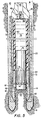
- FIG. 4 there is illustrated the preferred embodiment of the present invention wherein like numerals refer to like parts in the various figures.
- the core catcher sub 28 in Figures 1-3 is replaced by a core catcher sub 60 which is similar to the core catcher sub 28 and has an opening 62 for receiving the core therein.
- An inner barrel sub 64 is disposed between the core catcher 60 and the inner barrel 18 and threadedly engaged therewith.
- the lower portion of the inner barrel sub 64 has an annular member 66 disposed around the interior of the core receiving space.
- the annular member 66 has an O-ring 68 disposed in a receiving groove on the surface thereof for sealing with a piston 70 which is operable to reciprocate within the coring device 10.
- the piston 70 is designed to slideably fit within the spong 50 and to move upwards into the top interior space thereof.
- the O-ring 68 forms a liquid seal between the interior of the sponge 50 and the exterior environment of the coring device 10 when the piston 70 is disposed at the receiving end of the inner barrel 18. Therefore, communication between the exterior of the coring device 10 and the interior of the sponge 50 is prevented with the piston 70 disposed at the receiving end of the inner barrel 18.
- the piston 70 has a taper provided on the end thereof proximate the O-ring 68.
- the diameter of piston at the middle and upper portions thereof is slightly less than the member 66 whereas the diameter of piston 70 at the lower end thereof is essentially equal to the inner diameter of the 0- ring 78 in the uncompressed state.
- a cylindrical member 72 is disposed about the , piston 70 and adjacent the walls of the inner barrel sub 64 between the seating member 66 and the lower portion of the sponge 50.
- a ring member 74 is disposed between the cylindrical member 72 and the seating member 66.
- the ring member 74 has a plurality of upwardly reaching spring fingers 76 attached thereto which form a "core catcher" that prevents the core from falling out of the inner barrel.
- the piston 70 is held within the end of the coring device 10 by the O-ring 68 to prevent dislocation thereof. Until a core contacts the lower end of the piston 70, no movement will be imparted thereto.
- the sponge 50 has an interior space 78 that is filled with a fluid such as water at a predetermined pressure.
- the upper end of the inner barrel 18 has a quick disconnect fill plug 80 disposed therein to provide both a seal for the space 78 and also a path through which to pass the fluid. This sealed inner portion of the inner barrel 18 allows for pressurization thereof.
- the pressurized liquid contained within the interior 78 of the sponge 50 prevents contaminants from coming into contact with the exposed surface of the sponge 50 and being absorbed into the interstices thereof. As described above, it is important to present a clean sponge surface about the core that enters this space 78.
- the sponge 52 compresses. This compression is a result of the semi-closed cell structure of the sponge material. By compressing the sponge 52, some of the air trapped therein in the open interstices is forced into solution whereas the air with the closed cells is compressed. Upon relieving the pressure, the sponge 52 expands and the air in solution with the fluid escapes. As will be described hereinbelow, the fluid is removed prior to a reduction in pressure followed by a simultaneous entry of the core in the inner barrel 18.
- the embodiment of Figure 4 is illustrated in a well with a core 82 partially disposed within the interior 78 of the sponge 50.
- the O-ring 68 maintains a seal with the piston 70 until the mud column pressure exceeds the pressure within the space 78. When this pressure is exceeded, mud can then pass about this 0-ring seal.
- the fluid contained within the space 78 has a lower density than the mud.
- the fluid is water which weighs 8.34 pounds per U.S. gallon (1 kg/dm 3 ) whereas the mud surrounding the piston 70 weighs approximately 10 pounds per gallon (1.2 kg/dm 3 ) in most operations.
- the difference in the densities between the mud and the water causes the lower density fluid to be maintained within the interior space 70 and the higher density drilling mud to remain outside.
- the only way for the water contained within the interior 78 to exit therefrom is for the O-ring seal to be broken and the interior pressure thereof increased such that the water flows downward and out the receiving end of the inner barrel 18.
- the piston 70 In order to break the 0-ring seal, the piston 70 must be displaced upward therein. To facilitate this, the core 82 contacting the lower end of the piston 70 causes it to advance upwards and break the O-ring seal. Once the 0-ring seal is broken, fluids contained within the space 78 flow downwards around the piston 70 and around the core 82 and about the coring bit 16. This efferent flow of fluid not only allows space for the piston 70 to advance upwards but also performs a cleansing function on the surfaces of the core 82. This cleansing function prevents mud caking on the sides of the core which facilitates absorption by the sponge and free movement of the core up within the interior of the coring device. The result is a clean surface on the sponge 50 and also a clean surface on the core 82.
- an apparatus for sponge coring that utilizes a sealed inner barrel disposed within an outer well coring barrel.
- the inner barrel is sealed at the upper end and has a piston disposed in the other end thereof with an O-ring seal disposed thereabout.
- a sponge is disposed around the inner walls of the inner barrel for receiving the core and absorbing fluids therefrom.
- the inner barrel is filled with a fluid that is pressurized.
- the piston is displaced upward by the core that enters the inner barrel and this upward movement causes the fluid contained within the inner barrel to pass outward about the piston and the core to wash mud away from the face of the core to expose a clean surface to the sponge.
- the fluid contained within the core prevents drilling mud from circulating about the sponge and contaminating the interstices thereof.
- the fluid in the container means may have a density higher than the density of the fluids external to the container means.
Landscapes
- Life Sciences & Earth Sciences (AREA)
- Engineering & Computer Science (AREA)
- Geology (AREA)
- Mining & Mineral Resources (AREA)
- Physics & Mathematics (AREA)
- Environmental & Geological Engineering (AREA)
- Fluid Mechanics (AREA)
- General Life Sciences & Earth Sciences (AREA)
- Geochemistry & Mineralogy (AREA)
- Drilling Tools (AREA)
- Investigation Of Foundation Soil And Reinforcement Of Foundation Soil By Compacting Or Drainage (AREA)
- Bidet-Like Cleaning Device And Other Flush Toilet Accessories (AREA)
- Telephone Function (AREA)
- Professional, Industrial, Or Sporting Protective Garments (AREA)
- Electrical Discharge Machining, Electrochemical Machining, And Combined Machining (AREA)
- Mechanical Treatment Of Semiconductor (AREA)
- Cleaning Implements For Floors, Carpets, Furniture, Walls, And The Like (AREA)
- Earth Drilling (AREA)
- Pharmaceuticals Containing Other Organic And Inorganic Compounds (AREA)
- Medicines Containing Material From Animals Or Micro-Organisms (AREA)
- Cleaning In General (AREA)
Claims (20)
Priority Applications (1)
| Application Number | Priority Date | Filing Date | Title |
|---|---|---|---|
| AT85307454T ATE44072T1 (de) | 1984-10-17 | 1985-10-16 | Verfahren und vorrichtung zur verhinderung einer verunreinigung von schwammhuelsen in kernbehaeltern. |
Applications Claiming Priority (2)
| Application Number | Priority Date | Filing Date | Title |
|---|---|---|---|
| US661893 | 1984-10-17 | ||
| US06/661,893 US4598777A (en) | 1983-07-13 | 1984-10-17 | Method and apparatus for preventing contamination of a coring sponge |
Publications (2)
| Publication Number | Publication Date |
|---|---|
| EP0182498A1 EP0182498A1 (de) | 1986-05-28 |
| EP0182498B1 true EP0182498B1 (de) | 1989-06-14 |
Family
ID=24655537
Family Applications (1)
| Application Number | Title | Priority Date | Filing Date |
|---|---|---|---|
| EP85307454A Expired EP0182498B1 (de) | 1984-10-17 | 1985-10-16 | Verfahren und Vorrichtung zur Verhinderung einer Verunreinigung von Schwammhülsen in Kernbehältern |
Country Status (8)
| Country | Link |
|---|---|
| US (1) | US4598777A (de) |
| EP (1) | EP0182498B1 (de) |
| JP (1) | JPS61172990A (de) |
| AT (1) | ATE44072T1 (de) |
| AU (1) | AU4848285A (de) |
| CA (1) | CA1237653A (de) |
| DE (1) | DE3571058D1 (de) |
| NO (1) | NO170300C (de) |
Families Citing this family (48)
| Publication number | Priority date | Publication date | Assignee | Title |
|---|---|---|---|---|
| US4638872A (en) * | 1985-04-01 | 1987-01-27 | Diamond Oil Well Drilling Company | Core monitoring device |
| US4716974A (en) * | 1986-07-21 | 1988-01-05 | Eastman Christensen Co | Method and apparatus for coring with an in situ core barrel sponge |
| DE4000677C2 (de) * | 1989-02-11 | 1997-09-25 | Fritzmeier Georg Gmbh & Co | Verwendung eines Geräts zur Entnahme eines Bodenprobenkörpers |
| GB9214928D0 (en) * | 1992-07-14 | 1992-08-26 | Subsidence Surveys Limited | Core sampling |
| US5360074A (en) * | 1993-04-21 | 1994-11-01 | Baker Hughes, Incorporated | Method and composition for preserving core sample integrity using an encapsulating material |
| US5482123A (en) * | 1993-04-21 | 1996-01-09 | Baker Hughes Incorporated | Method and apparatus for pressure coring with non-invading gel |
| US5494119A (en) * | 1994-07-12 | 1996-02-27 | Tully; Francis X. | Core sampling device |
| US5439065A (en) * | 1994-09-28 | 1995-08-08 | Western Atlas International, Inc. | Rotary sidewall sponge coring apparatus |
| US5546798A (en) * | 1995-05-12 | 1996-08-20 | Baker Hughes Incorporated | Method and composition for preserving core sample integrity using a water soluble encapsulating material |
| US6283228B2 (en) | 1997-01-08 | 2001-09-04 | Baker Hughes Incorporated | Method for preserving core sample integrity |
| US6216804B1 (en) | 1998-07-29 | 2001-04-17 | James T. Aumann | Apparatus for recovering core samples under pressure |
| RU2160820C2 (ru) * | 1999-03-26 | 2000-12-20 | Тюменский научно-исследовательский и проектный институт природного газа и газовых технологий | Керноприемное устройство |
| GB9913974D0 (en) | 1999-06-17 | 1999-08-18 | Bartette Pascal | Apparatus for handling geological samples |
| NL1015147C2 (nl) * | 2000-05-10 | 2001-11-15 | Eijkelkamp Agrisearch Equip Bv | Grondmonsternemer. |
| EG22761A (en) * | 2000-06-29 | 2003-07-30 | Shell Int Research | Method of transferring fluids through a permeable well lining |
| US6719070B1 (en) * | 2000-11-14 | 2004-04-13 | Baker Hughes Incorporated | Apparatus and methods for sponge coring |
| RU2198996C2 (ru) * | 2001-02-06 | 2003-02-20 | Дочернее общество с ограниченной ответственностью "Буровая компания открытого акционерного общества "ГАЗПРОМ" | Керноотборный снаряд |
| RU2197597C2 (ru) * | 2001-04-09 | 2003-01-27 | Общество с ограниченной ответственностью "ТюменНИИгипрогаз" | Двойной керноотборный снаряд |
| RU2200225C2 (ru) * | 2001-04-12 | 2003-03-10 | Общество с ограниченной ответственностью "ТюменНИИгипрогаз" | Двойной керноизолирующий снаряд |
| DE20107024U1 (de) * | 2001-04-24 | 2001-07-26 | Hilti Ag, Schaan | Werkzeug zum Entfernen eines Bohrkernes |
| US7055626B2 (en) * | 2002-03-15 | 2006-06-06 | Baker Hughes Incorporated | Core bit having features for controlling flow split |
| RU2250347C2 (ru) * | 2002-07-29 | 2005-04-20 | Ооо Нпо "Вктб" | Керноотборный снаряд гидроизолирующий |
| RU2244096C1 (ru) * | 2003-04-29 | 2005-01-10 | Дочернее общество с ограниченной ответственностью "Буровая компания открытого акционерного общества "ГАЗПРОМ" ") | Керноотборный снаряд |
| RU2252307C1 (ru) * | 2003-10-01 | 2005-05-20 | Сибирское научно-производственное предприятие бурового машиностроения (ЗАО НПП "СибБурМаш") | Керноотборный снаряд |
| RU2318981C1 (ru) * | 2006-06-23 | 2008-03-10 | Андрей Васильевич Секисов | Керноотборный снаряд |
| RU2362002C1 (ru) * | 2007-12-27 | 2009-07-20 | Закрытое акционерное общество "Научно-производственное предприятие "СибБурМаш" | Керноотборный снаряд |
| SI22761A (sl) * | 2009-07-22 | 2009-10-31 | Kmetijski inštitut Slovenije | Naprava za jemanje strukturno neporušenih vzorcev tal |
| WO2012125454A2 (en) | 2011-03-16 | 2012-09-20 | QCS Technologies Inc. | Pressure coring assembly and method |
| US9217306B2 (en) | 2011-10-03 | 2015-12-22 | National Oilwell Varco L.P. | Methods and apparatus for coring |
| CN102400654A (zh) * | 2011-11-27 | 2012-04-04 | 中国石油天然气集团公司 | 岩心打捞器 |
| CN102418520B (zh) * | 2011-12-31 | 2014-04-02 | 中国地质大学(北京) | 锁水型松散地层取样钻具 |
| US9803441B2 (en) | 2012-11-08 | 2017-10-31 | Flexidrill Limited | Seated hammer apparatus for core sampling |
| CN103195385B (zh) * | 2013-03-27 | 2015-12-23 | 中国石油大学(北京) | 带压湿钻取心钻头 |
| US9441434B2 (en) * | 2013-04-15 | 2016-09-13 | National Oilwell Varco, L.P. | Pressure core barrel for retention of core fluids and related method |
| US9869146B2 (en) * | 2013-04-17 | 2018-01-16 | Halliburton Energy Services, Inc. | Methods and apparatus for coring |
| US9926756B2 (en) | 2013-07-18 | 2018-03-27 | Baker Hughes Incorporated | Pressure compensation modules for coring tools, coring tools including pressure compensation modules, and related methods |
| US9567813B2 (en) * | 2013-07-18 | 2017-02-14 | Baker Hughes Incorporated | Coring tools exhibiting reduced rotational eccentricity and related methods |
| US9765585B2 (en) * | 2013-07-18 | 2017-09-19 | Baker Hughes Incorporated | Coring tools and methods for making coring tools and procuring core samples |
| CA2923566C (en) * | 2013-09-06 | 2017-09-12 | Baker Hughes Incorporated | Coring tools including core sample flap catcher and related methods |
| US10584550B2 (en) * | 2013-09-13 | 2020-03-10 | Halliburton Energy Services, Inc. | Sponge pressure equalization system |
| US9963946B2 (en) * | 2013-12-24 | 2018-05-08 | Halliburton Energy Services, Inc. | Method of filling a coring tool inner barrel with a coring fluid |
| US10072471B2 (en) | 2015-02-25 | 2018-09-11 | Baker Hughes Incorporated | Sponge liner sleeves for a core barrel assembly, sponge liners and related methods |
| RU2621814C2 (ru) * | 2015-11-25 | 2017-06-07 | Общество с ограниченной ответственностью "Фирма "Радиус-Сервис" | Керноотборный снаряд |
| WO2017130557A1 (ja) * | 2016-01-27 | 2017-08-03 | ハイテック株式会社 | 地下水の検出方法、ボーリング装置およびコア採取装置 |
| RU2629179C1 (ru) * | 2016-06-27 | 2017-08-25 | Общество с ограниченной ответственностью "Научно-производственное предприятие "СибБурМаш" | Бурголовка к керноотборному снаряду для отбора изолированного керна |
| JP6865100B2 (ja) * | 2017-05-24 | 2021-04-28 | 清水建設株式会社 | ボーリングビット及びボーリングコア採取方法 |
| RU175357U1 (ru) * | 2017-06-26 | 2017-12-01 | Федеральное государственное бюджетное учреждение науки Институт Земной коры Сибирского отделения Российской академии наук | Керноотборный снаряд |
| CN113137196B (zh) * | 2021-04-29 | 2022-04-22 | 四川大学 | 一种高温超高压旋转直线往复动密封测试装置 |
Family Cites Families (15)
| Publication number | Priority date | Publication date | Assignee | Title |
|---|---|---|---|---|
| US1815391A (en) * | 1929-09-13 | 1931-07-21 | Universal Engineering Company | Core drill with auxiliary reamer |
| US1857693A (en) * | 1929-10-07 | 1932-05-10 | Harry J Quintrell | Core barrel having core receptacle |
| US1853581A (en) * | 1930-05-17 | 1932-04-12 | John M Schmissrauter | Method and apparatus for scavenging core drills |
| US2264449A (en) * | 1939-04-12 | 1941-12-02 | Standard Oil Dev Co | Method and apparatus for coring |
| US2703697A (en) * | 1950-12-15 | 1955-03-08 | Robert D Walker | Process and apparatus for well coring |
| US2779195A (en) * | 1952-04-10 | 1957-01-29 | Simon Karl | Device for subsoil testing and taking of specimens |
| US2862691A (en) * | 1956-04-03 | 1958-12-02 | Jersey Prod Res Co | Coring bit assembly |
| US2789790A (en) * | 1956-06-13 | 1957-04-23 | Ii John H Kirby | Core drilling apparatus |
| US3064742A (en) * | 1958-09-05 | 1962-11-20 | Jersey Prod Res Co | Obtaining unaltered core samples |
| US3207240A (en) * | 1961-10-31 | 1965-09-21 | Tiefbohr Messdienst Leutert & | Apparatus for the drilling of and the protection of drill cores in deep-welldrilling operations |
| US3299959A (en) * | 1963-09-30 | 1967-01-24 | Cicero C Brown | Multiple string well packer |
| US3454117A (en) * | 1968-01-16 | 1969-07-08 | Exxon Production Research Co | Obtaining unaltered core samples of subsurface earth formations |
| US4114694A (en) * | 1977-05-16 | 1978-09-19 | Brown Oil Tools, Inc. | No-shock pressure plug apparatus |
| US4312414A (en) * | 1980-05-23 | 1982-01-26 | Diamond Oil Well Drilling Company | Method and apparatus for obtaining saturation data from subterranean formations |
| US4479557A (en) * | 1983-07-13 | 1984-10-30 | Diamond Oil Well Drilling Co. | Method and apparatus for reducing field filter cake on sponge cores |
-
1984
- 1984-10-17 US US06/661,893 patent/US4598777A/en not_active Expired - Lifetime
-
1985
- 1985-10-10 AU AU48482/85A patent/AU4848285A/en not_active Abandoned
- 1985-10-16 CA CA000493111A patent/CA1237653A/en not_active Expired
- 1985-10-16 DE DE8585307454T patent/DE3571058D1/de not_active Expired
- 1985-10-16 EP EP85307454A patent/EP0182498B1/de not_active Expired
- 1985-10-16 AT AT85307454T patent/ATE44072T1/de active
- 1985-10-16 NO NO854108A patent/NO170300C/no not_active IP Right Cessation
- 1985-10-17 JP JP60230057A patent/JPS61172990A/ja active Pending
Also Published As
| Publication number | Publication date |
|---|---|
| CA1237653A (en) | 1988-06-07 |
| EP0182498A1 (de) | 1986-05-28 |
| AU4848285A (en) | 1986-04-24 |
| US4598777A (en) | 1986-07-08 |
| ATE44072T1 (de) | 1989-06-15 |
| DE3571058D1 (en) | 1989-07-20 |
| NO170300B (no) | 1992-06-22 |
| NO854108L (no) | 1986-04-18 |
| JPS61172990A (ja) | 1986-08-04 |
| NO170300C (no) | 1992-09-30 |
Similar Documents
| Publication | Publication Date | Title |
|---|---|---|
| EP0182498B1 (de) | Verfahren und Vorrichtung zur Verhinderung einer Verunreinigung von Schwammhülsen in Kernbehältern | |
| US4479557A (en) | Method and apparatus for reducing field filter cake on sponge cores | |
| US3111169A (en) | Continuous retrievable testing apparatus | |
| US4690216A (en) | Formation fluid sampler | |
| Sayles et al. | A sampler for the in situ collection of marine sedimentary pore waters | |
| US4339948A (en) | Well formation test-treat-test apparatus and method | |
| US6026900A (en) | Multiple liner method for borehole access | |
| US4312414A (en) | Method and apparatus for obtaining saturation data from subterranean formations | |
| US4271704A (en) | Fluid sampling device and method of sampling fluid | |
| US5743343A (en) | Method and apparatus for fluid and soil sampling | |
| DE3070343D1 (en) | Method for recovering a retrievable core receiver in upward drilling and a recovery head for this purpose | |
| US4502553A (en) | Sponge coring apparatus with reinforced sponge | |
| Barnes | An in situ interstitial water sampler for use in unconsolidated sediments | |
| CA1097328A (en) | Method and core barrel apparatus for obtaining and retrieving subterranean formation samples | |
| US10435974B2 (en) | Activation modules for obstructing entrances to inner barrels of coring tools and related coring tools and methods | |
| CN117307074B (zh) | 一种天然气水合物冷冻取芯钻具与取芯方法 | |
| US3437138A (en) | Drill stem fluid sampler | |
| US5421419A (en) | Method and apparatus for fluid and soil sampling | |
| Dickens et al. | The pressure core sampler (PCS) on ODP Leg 201: General operations and gas release | |
| US4463804A (en) | Vented non-pressurized, uncontaminated well fluid sampler | |
| US3152639A (en) | Methods and apparatus for testing wells | |
| JPH06201542A (ja) | 密閉採水容器及びそれを用いた採水装置 | |
| EP0546062B1 (de) | Verfahren und vorrichtung zum zonenimprägnieren von holz | |
| US3151689A (en) | Apparatus for obtaining gas samples | |
| CA1108597A (en) | Biased lubricant compensator for an earth boring drill bit |
Legal Events
| Date | Code | Title | Description |
|---|---|---|---|
| PUAI | Public reference made under article 153(3) epc to a published international application that has entered the european phase |
Free format text: ORIGINAL CODE: 0009012 |
|
| AK | Designated contracting states |
Kind code of ref document: A1 Designated state(s): AT BE CH DE FR GB IT LI LU NL SE |
|
| 17P | Request for examination filed |
Effective date: 19861103 |
|
| 17Q | First examination report despatched |
Effective date: 19871117 |
|
| GRAA | (expected) grant |
Free format text: ORIGINAL CODE: 0009210 |
|
| AK | Designated contracting states |
Kind code of ref document: B1 Designated state(s): AT BE CH DE FR GB IT LI LU NL SE |
|
| PG25 | Lapsed in a contracting state [announced via postgrant information from national office to epo] |
Ref country code: SE Effective date: 19890614 Ref country code: LI Effective date: 19890614 Ref country code: CH Effective date: 19890614 Ref country code: AT Effective date: 19890614 |
|
| REF | Corresponds to: |
Ref document number: 44072 Country of ref document: AT Date of ref document: 19890615 Kind code of ref document: T |
|
| REF | Corresponds to: |
Ref document number: 3571058 Country of ref document: DE Date of ref document: 19890720 |
|
| ITF | It: translation for a ep patent filed | ||
| REG | Reference to a national code |
Ref country code: CH Ref legal event code: PL |
|
| PGFP | Annual fee paid to national office [announced via postgrant information from national office to epo] |
Ref country code: SE Payment date: 19891010 Year of fee payment: 5 |
|
| ET | Fr: translation filed | ||
| PLBE | No opposition filed within time limit |
Free format text: ORIGINAL CODE: 0009261 |
|
| STAA | Information on the status of an ep patent application or granted ep patent |
Free format text: STATUS: NO OPPOSITION FILED WITHIN TIME LIMIT |
|
| 26N | No opposition filed | ||
| ITPR | It: changes in ownership of a european patent |
Owner name: CESSIONE;DIAMANT BOART STRATABIT (USA) INC. |
|
| REG | Reference to a national code |
Ref country code: GB Ref legal event code: 732 |
|
| REG | Reference to a national code |
Ref country code: FR Ref legal event code: TP |
|
| ITTA | It: last paid annual fee | ||
| EPTA | Lu: last paid annual fee | ||
| PGFP | Annual fee paid to national office [announced via postgrant information from national office to epo] |
Ref country code: LU Payment date: 19941001 Year of fee payment: 10 |
|
| PGFP | Annual fee paid to national office [announced via postgrant information from national office to epo] |
Ref country code: BE Payment date: 19941109 Year of fee payment: 10 |
|
| PG25 | Lapsed in a contracting state [announced via postgrant information from national office to epo] |
Ref country code: LU Free format text: LAPSE BECAUSE OF NON-PAYMENT OF DUE FEES Effective date: 19951016 |
|
| PG25 | Lapsed in a contracting state [announced via postgrant information from national office to epo] |
Ref country code: BE Effective date: 19951031 |
|
| BERE | Be: lapsed |
Owner name: DIAMOND BOART-STRATABIT INC. Effective date: 19951031 |
|
| REG | Reference to a national code |
Ref country code: GB Ref legal event code: IF02 |
|
| PGFP | Annual fee paid to national office [announced via postgrant information from national office to epo] |
Ref country code: NL Payment date: 20020919 Year of fee payment: 18 |
|
| PGFP | Annual fee paid to national office [announced via postgrant information from national office to epo] |
Ref country code: FR Payment date: 20021003 Year of fee payment: 18 |
|
| PGFP | Annual fee paid to national office [announced via postgrant information from national office to epo] |
Ref country code: DE Payment date: 20021031 Year of fee payment: 18 |
|
| PGFP | Annual fee paid to national office [announced via postgrant information from national office to epo] |
Ref country code: GB Payment date: 20030915 Year of fee payment: 19 |
|
| REG | Reference to a national code |
Ref country code: GB Ref legal event code: 732E |
|
| PG25 | Lapsed in a contracting state [announced via postgrant information from national office to epo] |
Ref country code: NL Free format text: LAPSE BECAUSE OF NON-PAYMENT OF DUE FEES Effective date: 20040501 Ref country code: DE Free format text: LAPSE BECAUSE OF NON-PAYMENT OF DUE FEES Effective date: 20040501 |
|
| PG25 | Lapsed in a contracting state [announced via postgrant information from national office to epo] |
Ref country code: FR Free format text: LAPSE BECAUSE OF NON-PAYMENT OF DUE FEES Effective date: 20040630 |
|
| NLV4 | Nl: lapsed or anulled due to non-payment of the annual fee |
Effective date: 20040501 |
|
| REG | Reference to a national code |
Ref country code: FR Ref legal event code: ST |
|
| PG25 | Lapsed in a contracting state [announced via postgrant information from national office to epo] |
Ref country code: GB Free format text: LAPSE BECAUSE OF NON-PAYMENT OF DUE FEES Effective date: 20041016 |
|
| GBPC | Gb: european patent ceased through non-payment of renewal fee |
Effective date: 20041016 |