EP0182519B1 - Dispositif de fermeture pour récipients - Google Patents
Dispositif de fermeture pour récipients Download PDFInfo
- Publication number
- EP0182519B1 EP0182519B1 EP85307745A EP85307745A EP0182519B1 EP 0182519 B1 EP0182519 B1 EP 0182519B1 EP 85307745 A EP85307745 A EP 85307745A EP 85307745 A EP85307745 A EP 85307745A EP 0182519 B1 EP0182519 B1 EP 0182519B1
- Authority
- EP
- European Patent Office
- Prior art keywords
- closure
- projection
- orifice
- closure device
- end member
- Prior art date
- Legal status (The legal status is an assumption and is not a legal conclusion. Google has not performed a legal analysis and makes no representation as to the accuracy of the status listed.)
- Expired - Lifetime
Links
- 230000000295 complement effect Effects 0.000 claims description 3
- 241000282472 Canis lupus familiaris Species 0.000 description 13
- 239000000463 material Substances 0.000 description 7
- 239000004033 plastic Substances 0.000 description 7
- 229920003023 plastic Polymers 0.000 description 7
- 239000003814 drug Substances 0.000 description 3
- 238000002347 injection Methods 0.000 description 3
- 239000007924 injection Substances 0.000 description 3
- 239000006187 pill Substances 0.000 description 3
- 210000002105 tongue Anatomy 0.000 description 3
- 230000013011 mating Effects 0.000 description 2
- 238000013459 approach Methods 0.000 description 1
- 239000003086 colorant Substances 0.000 description 1
- 229940079593 drug Drugs 0.000 description 1
- 238000011065 in-situ storage Methods 0.000 description 1
- 238000001746 injection moulding Methods 0.000 description 1
- 238000000465 moulding Methods 0.000 description 1
- 230000002093 peripheral effect Effects 0.000 description 1
- 239000000126 substance Substances 0.000 description 1
- 230000000007 visual effect Effects 0.000 description 1
Images


Classifications
-
- B—PERFORMING OPERATIONS; TRANSPORTING
- B65—CONVEYING; PACKING; STORING; HANDLING THIN OR FILAMENTARY MATERIAL
- B65D—CONTAINERS FOR STORAGE OR TRANSPORT OF ARTICLES OR MATERIALS, e.g. BAGS, BARRELS, BOTTLES, BOXES, CANS, CARTONS, CRATES, DRUMS, JARS, TANKS, HOPPERS, FORWARDING CONTAINERS; ACCESSORIES, CLOSURES, OR FITTINGS THEREFOR; PACKAGING ELEMENTS; PACKAGES
- B65D50/00—Closures with means for discouraging unauthorised opening or removal thereof, with or without indicating means, e.g. child-proof closures
- B65D50/02—Closures with means for discouraging unauthorised opening or removal thereof, with or without indicating means, e.g. child-proof closures openable or removable by the combination of plural actions
- B65D50/04—Closures with means for discouraging unauthorised opening or removal thereof, with or without indicating means, e.g. child-proof closures openable or removable by the combination of plural actions requiring the combination of simultaneous actions, e.g. depressing and turning, lifting and turning, maintaining a part and turning another one
- B65D50/041—Closures with means for discouraging unauthorised opening or removal thereof, with or without indicating means, e.g. child-proof closures openable or removable by the combination of plural actions requiring the combination of simultaneous actions, e.g. depressing and turning, lifting and turning, maintaining a part and turning another one the closure comprising nested inner and outer caps or an inner cap and an outer coaxial annular member, which can be brought into engagement to enable removal by rotation
Definitions
- the invention relates to a closure device for containers, particularly a container such as a pill or other medicine bottle having a cylindrical opening.
- closure devices such as screw-threaded caps of containers with a screw-threaded opening such as a neck can be removed relatively easily by unscrewing. This can be dangerous when the container houses drugs, dangerous chemicals and the like and a child for example unscrews the closure device and gains access to the contents and then takes the contents with possibly harmful or even fatal results.
- Closure devices which seek to provide for safer or authorised opening of the container have been proposed, but they are generally complex and expensive.
- a closure device for a container with a cylindrical opening comprising first and second cylindrical closure members normally biassed apart and each with an end member and a cylindrical skirt member, first drive means between the first and second closure members for driving the members in unison in one sense only to mount the closure on the opening, and a second drive means operative on axial pressure on the closure to drive the closure in the opposite sense for removal from the opening,
- the second drive means comprises an orifice through the first or outer end member and a projection on the second or inner end member, the projection substantially closing the orifice on application of axial pressure
- the second drive means comprising a projection and orifice which are concentric with the axis of rotation of the closure members whereby on engagement of the projection in the orifice on application of said pressure the closure members are turnable in unison in the opposite sense to the one sense for removing the device from the opening substantially without canting thereof, characterised in that there is a removable cover means initially secured to and lying between the upper and lower planes defining the end member
- the orifice and projection may be of complementary shape.
- the orifice and projection may have a hexagonal shape as considered in plan view.
- the orifices may be radially arranged and equiangularly spaced around the first or outer end member and the projections may be diametrically arranged on the second or inner end member.
- the orifices and projections may be substantially rectangular in configuration as considered in plan view.
- the orifice may be substantially hexagonal and the projection rectangular in plan view.
- the orifice and projection may be substantially rectangular in plan view.
- the orifice and projection may in a further embodiment be substantially cruciform in plan view.
- the orifice and projection may be substantially arcuate in plan view.
- the or each cover may be secured to the end member by means which is frangible by the projection on said axial movement.
- the or each cover may have a tab and may be secured to the end member by means which is frangible on pulling the tab.
- the first drive means may comprise ratchet and teeth means between the first and second closure members.
- a container with a cylindrical opening including a closure device as hereinbefore defined mounted on the cylindrical opening.
- the inner and outer closure members may be formed from plastics material by injection moulding.
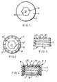
- the closure device 1 shown is injection moulded from plastics and is for mounting on an externally threaded cylindrical opening of a container (not shown) such as a pill or medicine bottle.
- the closure device 1 has a first or outer cylindrical closure member 2 and a second or inner cylindrical closure member 3, each with a respective end member 4 and 5 and a depending skirt member 6 and 7.
- first drive means between the first and second closure members 2 and 3 in the form of a series of peripheral upstanding teeth 8 on the end member 5 of the inner closure member 3 and a series of projecting lugs or bosses 9 on the end member 4 of the outer closure member 2 which engage the teeth 8 for turning the closure members 2 and 3 in unison in the clockwise sense only, to mount the closure device on the opening, screw threads 10 of the skirt member 7 of the inner closure member 3 engaging screw threads of the opening.
- the teeth 8 have inclined rear surfaces 11 so that if the outer closure member 2 is rotated in the opposite, anti-clockwise sense, the lugs or bosses 9 rise over the teeth 8 so that the inner and outer closure members 2 and 3 do not turn in unison in the anti-clockwise direction to open the container.
- the closure members 2 and 3 also include second drive means in the form of a centrally located orifice 12 through the end member 4 of the outer closure member 2 and an axially aligned projection 13 on the end member 5 of the inner closure member 3.
- the orifice 12 and projection 13 have respective cooperative driving means in the form of cooperable, angled flat driving surfaces 14 and 14', in this case arranged to form a hexagon.
- the projection 13 is below the orifice 12 as shown in Fig. 4. If it is desired for an authorised person to remove the safety closure 1 from a container opening to which it has been applied, it is merely necessary to apply axial pressure to the outer closure member 2 so that the orifice 12 rides round the projection 13, which is a close sliding fit in the orifice 12. If torque is now applied the faces 14 and 14' ensure that the projection and orifice engage in a non-slip fashion to drive the inner and outer members 2 and 3 in unison in the anti-clockwise or unscrewing sense. It will be understood that the axial pressure applied is applied to overcome the natural resilience of the engaged first drive means 8 and 9 sufficiently for the orifice 12 and projection 13 to be engaged for turning in the opposite sense. On release of the axial pressure, this natural resilience returns the closure members to the Fig. 4 or inoperative position.
- the orifice 12 may be initially closed by a film or disc of plastics formed during moulding and which is broken or removed by the projection 13 on first application of axial pressure, to indicate that a first opening of the container has been attempted.
- the inner and outer closure members are made of plastics of different colours, for example white for the outer closure member and red for the inner closure member.
- the projection and orifice can have any desired configuration providing they interlock for a driving action, for example they can be square, triangular or of any other configuration such as star-shape.
- a closure device 100 for a container having a cylindrical opening such as a pill bottle with a screw-threaded neck, has an inner closure member 102, and an outer closure member 103, which members each comprise an end member 104 and 105 respectively and a respective skirt member 106 and 107.
- the end members are spaced apart.
- First drive means 108 in the form of ratchets 109 and teeth 110 between the respective skirt members 106 and 107 drive the closure members in unison on rotation in a sense to mount the device 100 on the opening.
- the second drive means includes a frangible means 112 of the outer closure member 103 which is broken on such axial movement to engage the second drive means for rotational movement of the inner and outer closure members in unison in said opposite sense.
- the inner cylindrical closure member of cap 102 is smaller on its outer diameter than the inner diameter of the outer cylindrical closure member or cap 103, so there is a gap between the skirts 106 and 107 of the two caps in which the first drive means 108 is situated.
- the first drive means for turning the two caps 102 and 103 in unison on rotation in one sense to tighten the closure device on the opening of a bottle (not shown) (which has a thread for mating with a thread 113 of the skirt of the inner cap) comprises a series of equally circumferentially spaced apart said ratchets 109 on the outer (as viewed) surface of the skirt 106 and four said driving dogs 110 equidistantly circumferentially spaced apart on the inner (as viewed) surface of the skirt 107.
- the dogs 110 are resilient and the ratchets taper longitudinally upwardly as considered in use.
- the outer surface of the end member 104 of inner cap 102 has a central upstanding boss 114 and two lugs 115 diametrically spaced apart on opposite sides of the boss 14.
- the lugs 115 are elongate and radially directed.
- the end member 105 of the outer cap 103 has a circular depending wall 118 aligned with the boss 114 in the assembled closure device 100 and of slightly greater diameter than the boss 114 and of such a height that the skirt and boss just overlap in the position in which the closure device is in position on the opening (or neck) of a bottle.
- the end member of the outer cap also has a circular array of openings 116 similar shape to the lugs and of substantially the same size as the lugs 115. Moreover, the openings 116 are radially arranged in diametrically opposed pairs. Each opening is closed by the frangible means 112 in the form of covers which are made of material of the cap 103 which is thinner than the rest of the cap 103 and is connected to the rest of the cap by frangible connections. Each lug 115 and opening 116 is rectangular in the embodiment shown. The openings 116 and the lugs 115 comprise the second drive means.
- Both inner and outer caps 102 and 103 are injection moulded in one shot from plastics material.
- the inner and outer caps 102 and 103 are assembled together by springing the inner cap 102 over a retaining ring 119 of the skirt of the outer cap 103, an outwardly directed circumferential ring 120 of the skirt of the inner cap 102 serving to maintain the skirts 106 and 107 at the correct spacing and preventing the outer skirt from being squeezed by inner pressure forcibly to remove the closure device from the opening in use.
- the closure device 100 In order to mount the closure device 100 on the opening of a bottle, the closure device 100 is offered up to the bottle so that the threads are engaged, and the device 100 is screwed onto the bottle on rotation being applied to the outer cap 103.
- the dogs and ratchets 109 and 110 engage to drive the inner and outer caps 102 and 103 in unison in the screwing-on position.
- the taper of the dogs and ratchets 109 and 110 keeps the end members 103 and 104 apart with the tongues 117 clear of the end member 104 of the inner cap 102.
- the second drive means is now engaged, the lugs 115 engaging the sides of the associated openings 116 so that the caps 102 and 103 can be turned in unison to remove the device 100 from the opening.
- the tongues and tapered ratchets and dogs return the inner and outer caps to the initial position shown in Fig. 9, in which the second drive means is disengaged.
- the boss 114 and wall 118 act as a telescopic guide.
- frangible means 112 broken off from the openings indicates that the device has been removed at least once; in fact the broken off material provides tamper evidence. It will be appreciated that there is a plurality of pairs of openings 116 each axially covered by frangible means 112 and only one pair is utilised at any one removal. Therefore as the openings are each temporarily closed by removable material, the closure device embodying the invention provides a multiple taper evident closure. Stated in another way, a closure device embodying the invention can indicate that a plurality of attempts have been made to tamper with the device.
- a closure device 200 for a container has inner and outer closure members 202 and 203 both injection moulded from plastics material.
- the outer closure member 202 has an end member 204 and a skirt member (not shown).
- the inner closure member 203 has an end member 205 and a skirt member (not shown).
- the inner closure member 203 is permanently inside the outer closure member 202, and first driving means in the form of ratchets and dogs (also not shown but similar to those described for the second embodiment) on the skirt members engage to drive the inner and outer closure members 202 and 203 on rotation in unison in a direction to mount the closure device 200 on an opening, usually a screw-threaded neck of a bottle or jar the inner surface of the skirt of the inner closure member 203 having threads for mating with the screw-threaded neck.
- first driving means in the form of ratchets and dogs (also not shown but similar to those described for the second embodiment) on the skirt members engage to drive the inner and outer closure members 202 and 203 on rotation in unison in a direction to mount the closure device 200 on an opening, usually a screw-threaded neck of a bottle or jar the inner surface of the skirt of the inner closure member 203 having threads for mating with the screw-threaded neck.
- Rotation in the opposite sense causes the dogs and ratchets to ride over one another, without operative engagement, so that the outer closure member 202 rotates with respect of the inner closure member 203 and the closure device 200 as a whole stays mounted on the neck.
- a second drive means comprising a through opening 206 in the end member 204 of the outer closure member 202 and an upstanding dog 207 of complementary shape which is on the end member 205 of the inner closure member 203.
- the dog 207 is below the inner surface of end member 204 of the outer closure member 202, which end member 204 is spaced from the end member 205 of the inner closure member 203.
- the end members 204 and 205 are maintained apart by the dogs and ratchets between the skirt members, which taper longitudinally to provide this spacing, which is the usual disposition.
- the through opening 206 has integrally formed therein a member 208 which is connected to the boundary of the opening 206 by frangible means in the form of a relatively thin skin 209 of plastics all the way round.
- the member 208 also has an upstanding tab 210.
- the member 208 itself conforms to the shape of the openings 206 (Figs.11, 11A) or extends across the opening (Fig.10) and is connected by the thin skin 209 to part of the second drive means in the form of the boundary wall of the opening 206.
- the member 208 conceals the second drive means because in situ it is not evident how the closure device 200 is to be removed from the neck.
- the removal of the member 208 to expose the opening 206 also provides a visual guide for actuation of the second drive means.
Landscapes
- Engineering & Computer Science (AREA)
- Mechanical Engineering (AREA)
- Closures For Containers (AREA)
- Refuse Collection And Transfer (AREA)
Claims (13)
- Dispositif de fermeture pour un récipient à ouverture cylindrique, comprenant une première pièce de fermeture (2) et une deuxième pièce de fermeture (3), normalement maintenues séparées, chacune possédant une pièce terminale et une jupe cylindrique, un premier moyen d'entraînement entre la première et la deuxième pièce de fermeture pour entraîner les pièces à l'unisson dans un sens seulement pour monter la fermeture sur l'ouverture, et un deuxième moyen d'entraînement fonctionnant par pression axiale sur la fermeture pour entraîner la fermeture dans le sens opposé pour l'écarter de l'ouverture, dans lequel le deuxième moyen d'entraînement comprend un orifice (12) à travers la première pièce terminale (2), ou pièce terminale extérieure, et une projection (13) sur la deuxième pièce terminale ou pièce terminale intérieure, la projection (13) fermant substantiellement l'orifice (12) lors de l'application d'une pression axiale, le deuxième moyen d'entraînement comprenant une projection (13) et un orifice (12) concentriques à l'axe de rotation des pièces de fermeture (2, 3) de sorte que par engagement de la projection (13) dans l'orifice (12), par application de ladite pression, les pièces de fermeture (2, 3) peuvent être tournées à l'unisson dans le sens opposé au premier sens pour écarter le dispositif de l'ouverture pratiquemment sans coincement, caractérisé par la présence d'un couvercle amovible (112, 208) initialement fixé aux plans supérieurs et inférieurs, et situé entre ceux-ci, qui délimitent la pièce terminale de la première pièce de fermeture et fermant au moins partiellement l'orifice (12, 116, 206) dans la position où les pièces de fermeture (2 et 3, 102 et 103, 202 et 203) sont maintenues normalement séparées, et écarté de ladite pièce terminale par la projection (13, 115, 207) sur ledit engagement de ladite projection (13, 115, 207) dans l'orifice (12, 116, 206), pour permettre à l'usager de déterminer si une première ouverture du récipient s'est produite.
- Dispositif de fermeture selon la revendication 1, caractérisé en ce que l'orifice (12, 116, 206) et la projection (13, 115, 207) sont de formes complémentaires.
- Dispositif de fermeture selon la revendication 2, caractérisé en ce que l'orifice (12) et la projection (13) ont, en vue plane, une forme exagonale.
- Dispositif de fermeture selon la revendication 1, caractérisé par une pluralité d'orifices (116) et de projections (115), de préférence par huit orifices (116) et deux projections (115).
- Dispositif de fermeture selon la revendication 4, caractérisé en ce que les orifices (116) sont disposés radialement et séparés par des angles égaux, autour de la première pièce terminale (103) ou pièce extérieure, et que les projections (115) peuvent être disposées diamétralement sur la deuxième pièce (102) ou pièce intérieure terminale.
- Dispositif de fermeture selon la revendication 5, caractérisé en ce que les orifices (116) et les projections (115) ont une configuration, en vue plane, substantiellement rectangulaire.
- Dispositif de fermeture selon la revendication 1, caractérisé en ce que l'orifice (206) est substantiellement exagonal et que la projection (207) est rectangulaire, en vue plane.
- Dispositif de fermeture selon la revendication 2, caractérisé en ce que l'orifice (206) et la projection (207) sont, en vue plane, substantiellement rectangulaires.
- Dispositif de fermeture selon la revendication 2, caractérisé en ce que l'orifice (206) et la projection (207) sont, en vue plane, substantiellement cruciformes.
- Dispositif de fermeture selon la revendication 2, caractérisé en ce que l'orifice (206) et la projection (207) sont, en vue plane, de forme substantiellement arquée.
- Dispositif de fermeture selon l'une quelquonque des revendications précédentes, caractérisé en ce que le couvercle ou chaque couvercle (112, 208) est fixé à la pièce terminale (2, 103, 202) par un moyen qui est destructible par la projection (13, 115, 207) lors dudit mouvement axial.
- Dispositif de fermeture selon l'une quelquonque des revendications 1 à 10, caractérisé en ce que le couvercle ou chaque couvercle (208) peut posséder une patte (210) et en ce que le ou chaque couvercle (208) est fixé à la pièce terminale par un moyen (209) qui est destructible en tirant la patte (210).
- Un récipient avec une ouverture cylindrique, caractérisé par un dispositif de fermeture (1, 100, 200) selon l'une quelquonque des revendications précédentes, monté sur l'ouverture cylindrique.
Priority Applications (1)
| Application Number | Priority Date | Filing Date | Title |
|---|---|---|---|
| AT85307745T ATE76030T1 (de) | 1984-11-12 | 1985-10-25 | Verschlussanordnung fuer behaelter. |
Applications Claiming Priority (6)
| Application Number | Priority Date | Filing Date | Title |
|---|---|---|---|
| GB8428547 | 1984-11-12 | ||
| GB848428547A GB8428547D0 (en) | 1984-11-12 | 1984-11-12 | Safety closure for containers |
| GB8501843 | 1985-01-24 | ||
| GB858501843A GB8501843D0 (en) | 1985-01-24 | 1985-01-24 | Closure device for container |
| GB8502181 | 1985-01-29 | ||
| GB858502181A GB8502181D0 (en) | 1985-01-29 | 1985-01-29 | Closure device |
Publications (3)
| Publication Number | Publication Date |
|---|---|
| EP0182519A2 EP0182519A2 (fr) | 1986-05-28 |
| EP0182519A3 EP0182519A3 (en) | 1988-03-02 |
| EP0182519B1 true EP0182519B1 (fr) | 1992-05-13 |
Family
ID=27262516
Family Applications (1)
| Application Number | Title | Priority Date | Filing Date |
|---|---|---|---|
| EP85307745A Expired - Lifetime EP0182519B1 (fr) | 1984-11-12 | 1985-10-25 | Dispositif de fermeture pour récipients |
Country Status (7)
| Country | Link |
|---|---|
| US (1) | US4673095A (fr) |
| EP (1) | EP0182519B1 (fr) |
| AU (1) | AU585903B2 (fr) |
| CA (1) | CA1291722C (fr) |
| DE (1) | DE3586038D1 (fr) |
| ES (1) | ES296675Y (fr) |
| IE (1) | IE56699B1 (fr) |
Families Citing this family (41)
| Publication number | Priority date | Publication date | Assignee | Title |
|---|---|---|---|---|
| AU579288B1 (en) * | 1987-10-02 | 1988-11-17 | Vere Athol Williamson | Tamper evident safety cap |
| GB2210360A (en) * | 1987-10-02 | 1989-06-07 | Vere Athol Williamson | Safety caps |
| US5005718A (en) * | 1988-08-04 | 1991-04-09 | Van Blarcom Closures, Inc. | Tamper-evident child resistant closure device |
| JPH03502088A (ja) * | 1988-08-04 | 1991-05-16 | バン ブラーコム クロージャーズ,インコーポレイテッド | いたずら開封顕示・子供開封防止用密閉具 |
| IT216531Z2 (it) * | 1989-04-21 | 1991-09-16 | Capsulit Srl | Chiusura di sicurezza in particolare per flaconi di medicinali o simili. |
| US4957210A (en) * | 1989-10-16 | 1990-09-18 | Owens-Illinois Closure Inc. | Child resistant closure |
| US4997096A (en) * | 1990-04-27 | 1991-03-05 | Owens-Illinois Closure, Inc. | Child resistant closures |
| GB9112259D0 (en) * | 1991-06-07 | 1991-07-24 | Wellcome Found | Cap for a container and opening means therefor |
| US5785194A (en) * | 1991-06-07 | 1998-07-28 | Warner-Lambert Company | Cap for a container and opening means therefor |
| JPH06509311A (ja) * | 1991-07-30 | 1994-10-20 | ザ ウエルカム ファウンデーション リミテッド | 容器のキャップ |
| US5588545A (en) * | 1991-09-23 | 1996-12-31 | Beeson And Sons Limited | Child-resistant and elderly friendly closure for containers |
| US5743419A (en) * | 1991-09-23 | 1998-04-28 | Beeson And Sons Limited | Container closure with a reinforced resilient blade |
| US5147052A (en) * | 1991-09-30 | 1992-09-15 | Sunbeam Plastics Corporation | Child resistant closure |
| US5316161A (en) * | 1993-04-20 | 1994-05-31 | Comar, Inc. | Child resistant closure |
| GB2298194A (en) * | 1995-02-24 | 1996-08-28 | Beeson & Sons Ltd | Child resistant closures for containers |
| GB2299985A (en) * | 1995-04-18 | 1996-10-23 | Beeson & Sons Ltd | Child resistant closure assemblies |
| US5960972A (en) * | 1996-11-15 | 1999-10-05 | Constancio Larguia, Sr. | Container cap with interlocked safety closure |
| GB9718956D0 (en) * | 1997-09-08 | 1997-11-12 | Dodge Leyton S | Child resistant closures |
| DE29807243U1 (de) * | 1998-04-22 | 1999-08-26 | Friedrich Sanner GmbH & Co KG Spritzgußwerk, 64625 Bensheim | Kindersicherer und originalitätsgesicherter Behälter-Verschluß |
| US6382444B1 (en) * | 1999-03-17 | 2002-05-07 | Sentinel Packaging Systems, Inc. | Tamper-evident plastic closure system with snap-on band |
| US6206216B1 (en) | 1999-07-26 | 2001-03-27 | Top Seal Corporation | Child-resistant cap |
| FR2814724B1 (fr) * | 2000-10-04 | 2003-04-04 | Airsec Sa | Dispositif de fermeture de securite a l'epreuve d'enfants par vissage d'un conteneur muni d'une embouchure a filet de vis |
| ITSV20010003A1 (it) * | 2001-01-17 | 2002-07-17 | Marco Cerracchio | Tappo ad apertura facilitata |
| US20040099627A1 (en) * | 2002-11-26 | 2004-05-27 | Yan Fu Chen | Safety cover |
| US20050145086A1 (en) * | 2004-01-05 | 2005-07-07 | Mohr Monte D. | Combination pencil sharpener bottle cap |
| WO2007011656A2 (fr) * | 2005-07-15 | 2007-01-25 | Dennis Brandon | Appareil de synchronisation de debouchonnage de contenant de medicaments |
| US20070199912A1 (en) * | 2006-02-08 | 2007-08-30 | Libohova Agjah I | Child resistant bottle cap |
| US8109396B1 (en) | 2006-03-31 | 2012-02-07 | Rexam Healthcare Packaging Inc. | Slide rails and friction surfaces for closure |
| US7815061B1 (en) * | 2006-03-31 | 2010-10-19 | Rexam Closures And Containers | Friction surface for push and turn child resistant closure |
| FR2916741B1 (fr) * | 2007-05-29 | 2009-08-28 | Airsec Soc Par Actions Simplif | Dispositif de fermeture a securite enfant,a vis et a bague temoin de premiere ouverture |
| GB0710568D0 (en) * | 2007-06-02 | 2007-07-11 | Verrall Daniel | Secure fire hydrant cap |
| US20090014404A1 (en) * | 2007-07-10 | 2009-01-15 | Berry Plastics Corporation | Convertible container closure |
| US8186526B2 (en) * | 2009-07-08 | 2012-05-29 | Rexam Healthcare Packaging Inc. | Child resistant closure with a stacking position |
| US9045265B2 (en) * | 2010-08-05 | 2015-06-02 | Gregory Mark Adamczak | Child proof closure cap for container with combined tilting and rotating operation |
| US9580213B2 (en) | 2014-12-15 | 2017-02-28 | Johnson & Johnson Consumer Inc. | Child resistant closure for a container |
| EP3260390B1 (fr) * | 2016-06-22 | 2019-12-04 | Clariant Healthcare Packaging (France) SAS | Couvercle extérieur pour une fermeture à l'épreuve des enfants, fermeture à l'épreuve des enfants, récipient pourvu d'une telle fermeture et son utilisation |
| US10414561B1 (en) | 2018-07-03 | 2019-09-17 | Pascal Holdings, LLC | Safety cap |
| US12006110B2 (en) * | 2020-12-18 | 2024-06-11 | Airnov, Inc. | Tamper-evident closure |
| IT202300012885A1 (it) * | 2023-06-22 | 2024-12-22 | Lumson Spa | Tappo |
| US20250074663A1 (en) * | 2023-09-05 | 2025-03-06 | Closure Systems International Inc. | Closure and package with closure |
| US12503283B1 (en) * | 2024-07-02 | 2025-12-23 | Terry Vovan | Innovative tamper-evident and child-safety container |
Family Cites Families (6)
| Publication number | Priority date | Publication date | Assignee | Title |
|---|---|---|---|---|
| CH517626A (de) * | 1969-12-03 | 1972-01-15 | Sandoz Ag | Sicherheitsschraubverschluss für Behälter mit einer mit einem Gewinde versehenen Öffnung, insbesondere für Flaschen |
| CH594536A5 (fr) * | 1975-07-11 | 1978-01-13 | Sas Trading | |
| NL8102296A (nl) * | 1981-05-11 | 1982-12-01 | Technoplast Bv | Schroefdop voor het afsluiten van een houder. |
| GB2100238B (en) * | 1981-06-04 | 1985-05-22 | Puresevic Peter J | A closure device for a container having a cylindrical opening |
| US4394916A (en) * | 1982-03-29 | 1983-07-26 | Owens-Illinois, Inc. | Child-resistant closure assembly |
| DE3417184A1 (de) * | 1984-05-09 | 1985-11-14 | Technoplast B.V., Monster | Sicherungsverschluss |
-
1985
- 1985-10-11 ES ES1985296675U patent/ES296675Y/es not_active Expired
- 1985-10-25 EP EP85307745A patent/EP0182519B1/fr not_active Expired - Lifetime
- 1985-10-25 DE DE8585307745T patent/DE3586038D1/de not_active Expired - Fee Related
- 1985-10-30 CA CA000494282A patent/CA1291722C/fr not_active Expired - Lifetime
- 1985-10-31 AU AU49268/85A patent/AU585903B2/en not_active Ceased
- 1985-11-11 IE IE2802/85A patent/IE56699B1/xx unknown
- 1985-11-12 US US06/796,338 patent/US4673095A/en not_active Expired - Fee Related
Also Published As
| Publication number | Publication date |
|---|---|
| ES296675Y (es) | 1988-06-01 |
| US4673095A (en) | 1987-06-16 |
| AU4926885A (en) | 1986-05-22 |
| AU585903B2 (en) | 1989-06-29 |
| EP0182519A3 (en) | 1988-03-02 |
| CA1291722C (fr) | 1991-11-05 |
| IE852802L (en) | 1986-05-12 |
| IE56699B1 (en) | 1991-11-06 |
| DE3586038D1 (de) | 1992-06-17 |
| EP0182519A2 (fr) | 1986-05-28 |
| ES296675U (es) | 1987-12-16 |
Similar Documents
| Publication | Publication Date | Title |
|---|---|---|
| US4673095A (en) | Closure device for containers | |
| US4801028A (en) | Closure device for a container having a cylindrical opening | |
| US4461391A (en) | Tamper-resistant screw closure | |
| US4371088A (en) | Tamper indicating child resistant closure | |
| CA2168462C (fr) | Fermeture de contenant | |
| EP1040048B1 (fr) | Fermeture de securite | |
| US20100288765A1 (en) | Child safety closing device with first opening indicator screw and ring | |
| US4709823A (en) | Tamper evident bottle or package closure | |
| US3679085A (en) | Child-proof cap for medicine bottles | |
| US5005718A (en) | Tamper-evident child resistant closure device | |
| EP0792818B1 (fr) | Ensemble formé par un récipient et une fermeture de sécurité | |
| DE69916520T2 (de) | Originalitätsverschluss und Hals einer Flasche | |
| EP2173633B1 (fr) | Fermeture inviolable | |
| CA1257848A (fr) | Contenant antiviolation | |
| US5228593A (en) | Container-closure assembly | |
| GB2171679A (en) | Screw-type safety cap | |
| GB2282367A (en) | Container closures | |
| GB2142612A (en) | A child proof and tamper indicating closure | |
| GB2210360A (en) | Safety caps | |
| US20120085725A1 (en) | Child resistant screw cap | |
| GB2167050A (en) | Closure device for containers | |
| WO1985000344A1 (fr) | Dispositif de fermeture pour un conteneur possedant une ouverture cylindrique | |
| EP0434308B1 (fr) | Dispositif de fermeture | |
| WO1990001451A1 (fr) | Dispositif de fermeture inviolable par un enfant, a alteration visible | |
| JPS61164953A (ja) | 容器の封閉装置 |
Legal Events
| Date | Code | Title | Description |
|---|---|---|---|
| PUAI | Public reference made under article 153(3) epc to a published international application that has entered the european phase |
Free format text: ORIGINAL CODE: 0009012 |
|
| AK | Designated contracting states |
Kind code of ref document: A2 Designated state(s): AT BE CH DE FR GB IT LI LU NL SE |
|
| PUAL | Search report despatched |
Free format text: ORIGINAL CODE: 0009013 |
|
| AK | Designated contracting states |
Kind code of ref document: A3 Designated state(s): AT BE CH DE FR GB IT LI LU NL SE |
|
| 17P | Request for examination filed |
Effective date: 19880901 |
|
| 17Q | First examination report despatched |
Effective date: 19881031 |
|
| RAP1 | Party data changed (applicant data changed or rights of an application transferred) |
Owner name: METAL CLOSURES GROUP PLC |
|
| GRAA | (expected) grant |
Free format text: ORIGINAL CODE: 0009210 |
|
| AK | Designated contracting states |
Kind code of ref document: B1 Designated state(s): AT BE CH DE FR GB IT LI LU NL SE |
|
| PG25 | Lapsed in a contracting state [announced via postgrant information from national office to epo] |
Ref country code: SE Effective date: 19920513 Ref country code: LI Effective date: 19920513 Ref country code: IT Free format text: LAPSE BECAUSE OF FAILURE TO SUBMIT A TRANSLATION OF THE DESCRIPTION OR TO PAY THE FEE WITHIN THE PRESCRIBED TIME-LIMIT;WARNING: LAPSES OF ITALIAN PATENTS WITH EFFECTIVE DATE BEFORE 2007 MAY HAVE OCCURRED AT ANY TIME BEFORE 2007. THE CORRECT EFFECTIVE DATE MAY BE DIFFERENT FROM THE ONE RECORDED. Effective date: 19920513 Ref country code: CH Effective date: 19920513 Ref country code: AT Effective date: 19920513 |
|
| REF | Corresponds to: |
Ref document number: 76030 Country of ref document: AT Date of ref document: 19920515 Kind code of ref document: T |
|
| REF | Corresponds to: |
Ref document number: 3586038 Country of ref document: DE Date of ref document: 19920617 |
|
| REG | Reference to a national code |
Ref country code: CH Ref legal event code: PL |
|
| ET | Fr: translation filed | ||
| PG25 | Lapsed in a contracting state [announced via postgrant information from national office to epo] |
Ref country code: LU Free format text: LAPSE BECAUSE OF NON-PAYMENT OF DUE FEES Effective date: 19921031 |
|
| PLBE | No opposition filed within time limit |
Free format text: ORIGINAL CODE: 0009261 |
|
| STAA | Information on the status of an ep patent application or granted ep patent |
Free format text: STATUS: NO OPPOSITION FILED WITHIN TIME LIMIT |
|
| 26N | No opposition filed | ||
| PGFP | Annual fee paid to national office [announced via postgrant information from national office to epo] |
Ref country code: DE Payment date: 19960928 Year of fee payment: 12 |
|
| PGFP | Annual fee paid to national office [announced via postgrant information from national office to epo] |
Ref country code: FR Payment date: 19961009 Year of fee payment: 12 |
|
| PGFP | Annual fee paid to national office [announced via postgrant information from national office to epo] |
Ref country code: GB Payment date: 19961017 Year of fee payment: 12 |
|
| PGFP | Annual fee paid to national office [announced via postgrant information from national office to epo] |
Ref country code: NL Payment date: 19961031 Year of fee payment: 12 |
|
| PGFP | Annual fee paid to national office [announced via postgrant information from national office to epo] |
Ref country code: BE Payment date: 19961104 Year of fee payment: 12 |
|
| PG25 | Lapsed in a contracting state [announced via postgrant information from national office to epo] |
Ref country code: GB Free format text: LAPSE BECAUSE OF NON-PAYMENT OF DUE FEES Effective date: 19971025 |
|
| PG25 | Lapsed in a contracting state [announced via postgrant information from national office to epo] |
Ref country code: FR Free format text: THE PATENT HAS BEEN ANNULLED BY A DECISION OF A NATIONAL AUTHORITY Effective date: 19971031 Ref country code: BE Free format text: LAPSE BECAUSE OF NON-PAYMENT OF DUE FEES Effective date: 19971031 |
|
| BERE | Be: lapsed |
Owner name: METAL CLOSURES GROUP P.L.C. Effective date: 19971031 |
|
| PG25 | Lapsed in a contracting state [announced via postgrant information from national office to epo] |
Ref country code: NL Free format text: LAPSE BECAUSE OF NON-PAYMENT OF DUE FEES Effective date: 19980501 |
|
| GBPC | Gb: european patent ceased through non-payment of renewal fee |
Effective date: 19971025 |
|
| NLV4 | Nl: lapsed or anulled due to non-payment of the annual fee |
Effective date: 19980501 |
|
| PG25 | Lapsed in a contracting state [announced via postgrant information from national office to epo] |
Ref country code: DE Free format text: LAPSE BECAUSE OF NON-PAYMENT OF DUE FEES Effective date: 19980701 |
|
| REG | Reference to a national code |
Ref country code: FR Ref legal event code: ST |