EP0182547B1 - Transmission d'entraînement sur un voilier - Google Patents
Transmission d'entraînement sur un voilier Download PDFInfo
- Publication number
- EP0182547B1 EP0182547B1 EP85308087A EP85308087A EP0182547B1 EP 0182547 B1 EP0182547 B1 EP 0182547B1 EP 85308087 A EP85308087 A EP 85308087A EP 85308087 A EP85308087 A EP 85308087A EP 0182547 B1 EP0182547 B1 EP 0182547B1
- Authority
- EP
- European Patent Office
- Prior art keywords
- inputs
- drive
- distributor
- outputs
- shaft
- Prior art date
- Legal status (The legal status is an assumption and is not a legal conclusion. Google has not performed a legal analysis and makes no representation as to the accuracy of the status listed.)
- Expired - Lifetime
Links
- 230000005540 biological transmission Effects 0.000 title claims description 25
- 230000008878 coupling Effects 0.000 claims description 7
- 238000010168 coupling process Methods 0.000 claims description 7
- 238000005859 coupling reaction Methods 0.000 claims description 7
- 241000282472 Canis lupus familiaris Species 0.000 description 12
- 230000000712 assembly Effects 0.000 description 2
- 238000000429 assembly Methods 0.000 description 2
- 230000000694 effects Effects 0.000 description 2
- 230000003387 muscular Effects 0.000 description 2
- 230000002860 competitive effect Effects 0.000 description 1
- 238000010586 diagram Methods 0.000 description 1
- 230000007935 neutral effect Effects 0.000 description 1
- 238000006467 substitution reaction Methods 0.000 description 1
Images

Classifications
-
- B—PERFORMING OPERATIONS; TRANSPORTING
- B66—HOISTING; LIFTING; HAULING
- B66D—CAPSTANS; WINCHES; TACKLES, e.g. PULLEY BLOCKS; HOISTS
- B66D1/00—Rope, cable, or chain winding mechanisms; Capstans
- B66D1/60—Rope, cable, or chain winding mechanisms; Capstans adapted for special purposes
- B66D1/74—Capstans
- B66D1/7463—Accessories
- B66D1/7468—Handles
-
- B—PERFORMING OPERATIONS; TRANSPORTING
- B63—SHIPS OR OTHER WATERBORNE VESSELS; RELATED EQUIPMENT
- B63H—MARINE PROPULSION OR STEERING
- B63H9/00—Marine propulsion provided directly by wind power
- B63H9/04—Marine propulsion provided directly by wind power using sails or like wind-catching surfaces
- B63H9/08—Connections of sails to masts, spars, or the like
- B63H9/10—Running rigging, e.g. reefing equipment
-
- B—PERFORMING OPERATIONS; TRANSPORTING
- B66—HOISTING; LIFTING; HAULING
- B66D—CAPSTANS; WINCHES; TACKLES, e.g. PULLEY BLOCKS; HOISTS
- B66D1/00—Rope, cable, or chain winding mechanisms; Capstans
- B66D1/60—Rope, cable, or chain winding mechanisms; Capstans adapted for special purposes
- B66D1/74—Capstans
- B66D1/7421—Capstans having a vertical rotation axis
- B66D1/7431—Capstans having a vertical rotation axis driven manually only
-
- Y—GENERAL TAGGING OF NEW TECHNOLOGICAL DEVELOPMENTS; GENERAL TAGGING OF CROSS-SECTIONAL TECHNOLOGIES SPANNING OVER SEVERAL SECTIONS OF THE IPC; TECHNICAL SUBJECTS COVERED BY FORMER USPC CROSS-REFERENCE ART COLLECTIONS [XRACs] AND DIGESTS
- Y10—TECHNICAL SUBJECTS COVERED BY FORMER USPC
- Y10T—TECHNICAL SUBJECTS COVERED BY FORMER US CLASSIFICATION
- Y10T74/00—Machine element or mechanism
- Y10T74/19—Gearing
- Y10T74/19014—Plural prime movers selectively coupled to common output
-
- Y—GENERAL TAGGING OF NEW TECHNOLOGICAL DEVELOPMENTS; GENERAL TAGGING OF CROSS-SECTIONAL TECHNOLOGIES SPANNING OVER SEVERAL SECTIONS OF THE IPC; TECHNICAL SUBJECTS COVERED BY FORMER USPC CROSS-REFERENCE ART COLLECTIONS [XRACs] AND DIGESTS
- Y10—TECHNICAL SUBJECTS COVERED BY FORMER USPC
- Y10T—TECHNICAL SUBJECTS COVERED BY FORMER US CLASSIFICATION
- Y10T74/00—Machine element or mechanism
- Y10T74/19—Gearing
- Y10T74/19023—Plural power paths to and/or from gearing
- Y10T74/19126—Plural drivers plural driven
-
- Y—GENERAL TAGGING OF NEW TECHNOLOGICAL DEVELOPMENTS; GENERAL TAGGING OF CROSS-SECTIONAL TECHNOLOGIES SPANNING OVER SEVERAL SECTIONS OF THE IPC; TECHNICAL SUBJECTS COVERED BY FORMER USPC CROSS-REFERENCE ART COLLECTIONS [XRACs] AND DIGESTS
- Y10—TECHNICAL SUBJECTS COVERED BY FORMER USPC
- Y10T—TECHNICAL SUBJECTS COVERED BY FORMER US CLASSIFICATION
- Y10T74/00—Machine element or mechanism
- Y10T74/19—Gearing
- Y10T74/19219—Interchangeably locked
- Y10T74/19251—Control mechanism
- Y10T74/19279—Cam operated
Definitions
- This invention relates to the transmission of drive in sailing craft and particularly but not exclusively in competitive yachts where only manual drive is permitted in any of the operations of the yacht such as adjustment and hoisting of sails.
- one or more members of the crew may have as their sole or principal purpose the provision of manual power, being stationed at a device, equipped with one or more handles to which they apply their muscular strength. Drive is taken from the handles through a transmission system to serve all of the sheet-handling and other winches of the yachts. Other crew members will control how sheets or other items are applied to those winches.
- the transmission system may include a general speed reduction in the shape of one or more gearboxes and this or these may either be operated by the operator of the handle(s) or by some other crew member. Additionally or alternatively the individual winches may have multiple drive-transmission ratios within them, as between the transmission system of the yacht which is the input to that winch and the drum of that particular winch.
- the present invention is concerned with the transmission of drive from a drive device into the transmission system of the yacht.
- One known transmission system (not for a yacht) disclosed in UK Patent 1502704 has two inputs to two boxes which may be coupled (either collectively or individually) to one or both of two outputs from the respective boxes.
- the coupling is achieved by a displaceable pinion and bevel gear system associated with each input and a clutch coupling between the boxes.
- a distributor for distributing rotational drive in a sailing craft having a plurality of rotatable drive-input means (14, 15) a plurality of drive outputs (12, 13) and a plurality of transmission paths for coupling each of the inputs to one or more of the outputs characterized in that all of the inputs (14, 15); and outputs (12, 13) are coaxial.
- Drive between plural inputs into the transmission, from respective outputs of a drive device may be distributed in a plurality of ways: including both to one side and both to the other side and separately to each side of a two-sided transmission system of the yacht. This is without any change of speed; i.e. the inputs and outputs rotate at the same speed as each other.
- the distributor may be used to feed either or both of gearboxes situated at respective sides of the distributor, with independent control of the mode of distribution and of ratio selected in the or each gearbox.
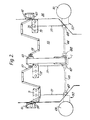
- a transmission distributor 1, Figure 1 has two outputs which are coupled through e.g. shafts and universal joints to transmission rods to go to respective sides of the sailing vessel under its decking.
- the purpose of the transmission distributor is to allow the output from input drive chains 2 to be applied together either to the starboard side of the yacht or to the port side or for drives to be applied separately to the port and starboard sides respectively.
- the distributor 1 consists of a main shaft 3 with parts 4, 5, 6.
- the centre part 5 has end portions 7, 8 and a splined middle 9; the outer parts 4, 6 have amplike portions 10, 11 surrounding the portions 7, and splined ends 12, 13 for output coupling to the transmission linkages.
- Chain drives 2 come in independently from the sprockets associated with two drive handles of a drive device and pass round sprockets 14, 15 both mounted rotatably on bearings on respective end portions 7, 8 of the centre part 5 of the shaft.
- Both axial faces of the sprockets 14 and 15 have at least two castellations 16, 17 forming part of respective dog clutch assemblies.
- cam shaft 20 Parallel to the shaft 3 there is a cam shaft 20 on which are four face cams 21,22,23 and 24, face cams 21 and 24 having a single ramp such as 25 and 22 and 23 having a double ramp surface such as 26, 27.
- Each cam is set at a predetermined angular relationship to each other on the shaft 20, with preferred orientations of the shaft being determined by the engagement of spring detent plungers 28 with slots in the periphery of the face cams.
- cam 21 In a third position of rotation of the shaft 20 cam 21 remains clear of disc 30, cams 22 and 23 only present a thin part of their thickness to the associated discs 31, 32 so that their dogs thereby remain engaged but cam 24 has presented its full thickness to disc 33 whose dogs are thereby held disengaged, and the drive from both the sprockets is transmitted together to the left hand part 6 of the main shaft.
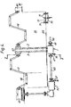
- the distributor may be used with or without a gearbox for equipping a drive-transmission system, we will now describe by way of example a layout for a large competition yacht where both are used in one system.
- crank-drive handles 57, 58 are journalled at the outermost ends in bearings 59, 60 on the deck, which in this example also house spinnaker sheet lead rollers 61, 62.
- the mutually nearer ends of the crank-handles are journalled in a housing 63 in which sprockets on the handles engage the respective drive chains 2 leading to the sprockets 14,15 in the distributor 1 mounted below the sole 64 of the cockpit.
- Transmission shafts 65, 66 are coupled to the outputs 12, 13 of the distributor and to the inputs of respective gearboxes 50 through universal joints 67, 68.
- each gearbox is via a bevel box and transmission shaft to a main winch 69, 70.
- Transmission shafts may additionally or alternatively lead to other winches on the yacht.
- Control of the cam shaft of the distributor 1 is by means of foot pedal assemblies 72 mounted in the sole of the cockpit.
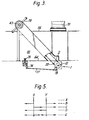
- the same assembly may also be used for control of the gearboxes, and a more detailed description will be given with reference to such an assembly 73 controlling a gearbox 50.
- One of three rotational settings of a shaft 74 ( Figure 4) in each assembly is assured by pressing down one of three foot pedals 75 linked to the shaft 74 by crank arms.
- a further crank arm 76 is pivoted to a link arm 77 which at its far end is pivoted to a crank arm 78 on the cam shaft 20 of the gear box or distributor.
- the muscular effort exerted on the handles 57, 58 may be applied both to one side or to the other of the yacht, or separately to the two sides, and in any case through any one of the ratios available in the respective gearboxes.
- Control of gear change within the gearboxes may be by any suitable means, including dog-clutches controlled by face cams as in the distributor just described.
- the dog-clutches in the distributor may be driven into or out of engagement by any suitable means for example electromechanical or pneumatic drives and where a cam-shaft such as 20 is used, its setting may be assured either by mechanical lever linkages as shown or directly through a gear-stick or otherwise e.g. hydraulically.
- X and Y are the two drive inputs (e.g. sprockets 14, 15 of the embodiment).
- Position A shows neutrality, no connection to the outputs.
- Position B shows separate drive to the two outputs, C both drives to one output and D both drives to the other.
- E shows both drives going in common to both outputs.
Landscapes
- Engineering & Computer Science (AREA)
- Mechanical Engineering (AREA)
- Life Sciences & Earth Sciences (AREA)
- Sustainable Development (AREA)
- Sustainable Energy (AREA)
- Chemical & Material Sciences (AREA)
- Combustion & Propulsion (AREA)
- Ocean & Marine Engineering (AREA)
- Structure Of Transmissions (AREA)
Claims (9)
Applications Claiming Priority (2)
| Application Number | Priority Date | Filing Date | Title |
|---|---|---|---|
| GB8429164 | 1984-11-19 | ||
| GB848429164A GB8429164D0 (en) | 1984-11-19 | 1984-11-19 | Drive transmission in sailing craft |
Publications (3)
| Publication Number | Publication Date |
|---|---|
| EP0182547A2 EP0182547A2 (fr) | 1986-05-28 |
| EP0182547A3 EP0182547A3 (en) | 1987-11-25 |
| EP0182547B1 true EP0182547B1 (fr) | 1990-05-23 |
Family
ID=10569925
Family Applications (1)
| Application Number | Title | Priority Date | Filing Date |
|---|---|---|---|
| EP85308087A Expired - Lifetime EP0182547B1 (fr) | 1984-11-19 | 1985-11-06 | Transmission d'entraînement sur un voilier |
Country Status (5)
| Country | Link |
|---|---|
| US (1) | US4823630A (fr) |
| EP (1) | EP0182547B1 (fr) |
| AU (1) | AU583864B2 (fr) |
| DE (1) | DE3577831D1 (fr) |
| GB (1) | GB8429164D0 (fr) |
Families Citing this family (5)
| Publication number | Priority date | Publication date | Assignee | Title |
|---|---|---|---|---|
| IT1244518B (it) * | 1991-01-18 | 1994-07-15 | Transtyle Ltd | Gruppo motore per il comando di una macchina atta alla produzione di prodotti alimentari pastosi e/o a comportamento fluido |
| AU5563400A (en) * | 2000-04-28 | 2001-11-12 | Jaidip Nautamlal Shah | Independent multi output drive |
| EP2058225B1 (fr) * | 2007-11-07 | 2011-10-19 | Harken Italy S.p.A. | Socle pour bateau à voile |
| WO2022190323A1 (fr) * | 2021-03-11 | 2022-09-15 | 株式会社アイトロニクス | Mécanisme de transmission |
| EP4707219A1 (fr) * | 2024-09-06 | 2026-03-11 | Antal S.r.l. | Système de transmission pour la manouvre des cordages de voile sur des navires à voile |
Family Cites Families (20)
| Publication number | Priority date | Publication date | Assignee | Title |
|---|---|---|---|---|
| DE125349C (fr) * | ||||
| DE211398C (fr) * | ||||
| US1538125A (en) * | 1923-12-17 | 1925-05-19 | John E Long | Winding device |
| DE506879C (de) * | 1928-03-21 | 1930-09-10 | Union Tool Company | Reibungskupplung |
| US1990810A (en) * | 1933-12-16 | 1935-02-12 | William T Young | Universal jack shaft |
| US2151881A (en) * | 1935-06-17 | 1939-03-28 | Wilson John Hart | Drilling rig transmission |
| DE697741C (de) * | 1936-12-19 | 1940-10-22 | Vasanta Maschinenfabrik Akt Ge | Schaltwerkswechselgetriebe mit umsteuerbarer Drehrichtung der Abtriebswelle |
| DE741550C (de) * | 1939-06-08 | 1943-11-12 | Carl Mueller | Ankerwinde mit Handkurbel- und Motorantrieb |
| DE728560C (de) * | 1939-11-29 | 1942-11-28 | Wanderer Werke Ag | Schaltglied, insbesondere fuer Wechselgetriebe |
| US2282616A (en) * | 1940-02-12 | 1942-05-12 | Nat Supply Co | Draw works |
| GB875447A (en) * | 1957-02-22 | 1961-08-23 | Hahn Eugen | Variable speed gearing for machine tools |
| GB977370A (en) * | 1962-04-19 | 1964-12-09 | Clyde Engineering Company Pty | A jib sheet winch |
| DE1226267B (de) * | 1965-02-11 | 1966-10-06 | Demag Ag | Sicherheitsvorrichtung gegen das Abstuerzen einer ueber Seile von zwei synchron angetriebenen Seiltrommeln gehobenen oder gesenkten Last |
| DE1942689A1 (de) * | 1969-08-21 | 1971-03-11 | Kiss Laszlo J | Transmissionsvorrichtung zum UEbertragen einer Vielzahl von Drehzahlen |
| US3733812A (en) * | 1970-04-22 | 1973-05-22 | Smith Berger Manuf Corp | Yarder having an infinite ratio driving interlock for spooling drums |
| FR2170285B1 (fr) * | 1973-05-18 | 1977-09-02 | Sefac | |
| DE2518753B2 (de) * | 1975-04-26 | 1981-03-12 | Eisenhütte Prinz Rudolph, Zweigniederlassung der Salzgitter Maschinen und Anlagen AG, 4408 Dülmen | Zweiträumige Schachtfördermaschine, insbesondere Ab- und Weiterteufhaspel |
| WO1979000932A1 (fr) * | 1978-04-14 | 1979-11-15 | J Tatterstal | Dispositif d'enroulement |
| AU8051782A (en) * | 1981-02-24 | 1982-09-02 | Messrs Exdin Engineering Pty. Ltd. | Winch drive mechanism |
| US4807852A (en) * | 1984-03-05 | 1989-02-28 | Barient, Inc. | Multi-pedestal winch system |
-
1984
- 1984-11-19 GB GB848429164A patent/GB8429164D0/en active Pending
-
1985
- 1985-11-06 EP EP85308087A patent/EP0182547B1/fr not_active Expired - Lifetime
- 1985-11-06 DE DE8585308087T patent/DE3577831D1/de not_active Expired - Lifetime
- 1985-11-12 US US06/797,014 patent/US4823630A/en not_active Expired - Fee Related
- 1985-11-13 AU AU49859/85A patent/AU583864B2/en not_active Ceased
Also Published As
| Publication number | Publication date |
|---|---|
| DE3577831D1 (de) | 1990-06-28 |
| AU4985985A (en) | 1986-05-29 |
| EP0182547A2 (fr) | 1986-05-28 |
| AU583864B2 (en) | 1989-05-11 |
| US4823630A (en) | 1989-04-25 |
| GB8429164D0 (en) | 1984-12-27 |
| EP0182547A3 (en) | 1987-11-25 |
Similar Documents
| Publication | Publication Date | Title |
|---|---|---|
| EP0377848B1 (fr) | Mécanisme de changement de vitesse commandé électriquement suivant X-Y | |
| DE3872520T2 (de) | Steuerung und manövrierung von wasserfahrzeugen. | |
| US4823630A (en) | Distributor for independently distributing rotational drive in a sailing craft | |
| US5033324A (en) | Gear-changing console | |
| US3981208A (en) | Sheet winch | |
| GB2248818A (en) | Lever type hoist with free rotation provision and load limitation | |
| DE3143019C2 (de) | Steuereinrichtung für ein Fahrzeuggetriebe | |
| JP4863133B2 (ja) | 係船装置 | |
| GB2051268A (en) | Speed-shift apparatus for sheet winch | |
| US5927691A (en) | Four speed sailboat winch having separate second gear | |
| DE19609723C2 (de) | Betätigungsvorrichtung für Fahrradgangschaltungen | |
| CA1185878A (fr) | Levier de commande unique | |
| EP1607323B1 (fr) | Système pneumatique pour utiliser l'accastillage de pont d'un voilier | |
| CA2299026A1 (fr) | Commande de changement de vitesse | |
| GB2152164A (en) | Bidirectional marine drive lower gear case | |
| AU2005222505A1 (en) | Motion transmission system for manoeuvring the ropes of sails in sailing boats | |
| US4048869A (en) | Shifting mechanism for control elements | |
| US2484921A (en) | Differential leverage brake transmission | |
| JP2524668Y2 (ja) | 耕耘機の回行装置 | |
| JPH09220946A (ja) | 作業用走行車 | |
| JPH052001Y2 (fr) | ||
| JPH045589B2 (fr) | ||
| KR900005909B1 (ko) | 수동 프레스기 | |
| US1691062A (en) | Steering gear | |
| KR900009096B1 (ko) | 4륜 구동형 트랙터 |
Legal Events
| Date | Code | Title | Description |
|---|---|---|---|
| PUAI | Public reference made under article 153(3) epc to a published international application that has entered the european phase |
Free format text: ORIGINAL CODE: 0009012 |
|
| AK | Designated contracting states |
Kind code of ref document: A2 Designated state(s): DE FR GB IT NL |
|
| PUAL | Search report despatched |
Free format text: ORIGINAL CODE: 0009013 |
|
| RHK1 | Main classification (correction) |
Ipc: B63B 21/16 |
|
| AK | Designated contracting states |
Kind code of ref document: A3 Designated state(s): DE FR GB IT NL |
|
| 17P | Request for examination filed |
Effective date: 19880227 |
|
| 17Q | First examination report despatched |
Effective date: 19890503 |
|
| GRAA | (expected) grant |
Free format text: ORIGINAL CODE: 0009210 |
|
| AK | Designated contracting states |
Kind code of ref document: B1 Designated state(s): DE FR GB IT NL |
|
| REF | Corresponds to: |
Ref document number: 3577831 Country of ref document: DE Date of ref document: 19900628 |
|
| ITF | It: translation for a ep patent filed | ||
| ET | Fr: translation filed | ||
| PLBE | No opposition filed within time limit |
Free format text: ORIGINAL CODE: 0009261 |
|
| STAA | Information on the status of an ep patent application or granted ep patent |
Free format text: STATUS: NO OPPOSITION FILED WITHIN TIME LIMIT |
|
| 26N | No opposition filed | ||
| ITTA | It: last paid annual fee | ||
| PGFP | Annual fee paid to national office [announced via postgrant information from national office to epo] |
Ref country code: GB Payment date: 19951027 Year of fee payment: 11 |
|
| PGFP | Annual fee paid to national office [announced via postgrant information from national office to epo] |
Ref country code: FR Payment date: 19951116 Year of fee payment: 11 |
|
| PGFP | Annual fee paid to national office [announced via postgrant information from national office to epo] |
Ref country code: NL Payment date: 19951120 Year of fee payment: 11 |
|
| PGFP | Annual fee paid to national office [announced via postgrant information from national office to epo] |
Ref country code: DE Payment date: 19951121 Year of fee payment: 11 |
|
| PG25 | Lapsed in a contracting state [announced via postgrant information from national office to epo] |
Ref country code: GB Effective date: 19961106 |
|
| PG25 | Lapsed in a contracting state [announced via postgrant information from national office to epo] |
Ref country code: NL Effective date: 19970601 |
|
| GBPC | Gb: european patent ceased through non-payment of renewal fee |
Effective date: 19961106 |
|
| PG25 | Lapsed in a contracting state [announced via postgrant information from national office to epo] |
Ref country code: FR Effective date: 19970731 |
|
| NLV4 | Nl: lapsed or anulled due to non-payment of the annual fee |
Effective date: 19970601 |
|
| PG25 | Lapsed in a contracting state [announced via postgrant information from national office to epo] |
Ref country code: DE Effective date: 19970801 |
|
| REG | Reference to a national code |
Ref country code: FR Ref legal event code: ST |