EP0182700A1 - Elément de connexion miniature à faible pas, et procédé de fabrication d'un tel élément de connexion - Google Patents
Elément de connexion miniature à faible pas, et procédé de fabrication d'un tel élément de connexion Download PDFInfo
- Publication number
- EP0182700A1 EP0182700A1 EP85402128A EP85402128A EP0182700A1 EP 0182700 A1 EP0182700 A1 EP 0182700A1 EP 85402128 A EP85402128 A EP 85402128A EP 85402128 A EP85402128 A EP 85402128A EP 0182700 A1 EP0182700 A1 EP 0182700A1
- Authority
- EP
- European Patent Office
- Prior art keywords
- strip
- wires
- mold
- connection element
- elastomer
- Prior art date
- Legal status (The legal status is an assumption and is not a legal conclusion. Google has not performed a legal analysis and makes no representation as to the accuracy of the status listed.)
- Granted
Links
Images


Classifications
-
- H—ELECTRICITY
- H01—ELECTRIC ELEMENTS
- H01R—ELECTRICALLY-CONDUCTIVE CONNECTIONS; STRUCTURAL ASSOCIATIONS OF A PLURALITY OF MUTUALLY-INSULATED ELECTRICAL CONNECTING ELEMENTS; COUPLING DEVICES; CURRENT COLLECTORS
- H01R43/00—Apparatus or processes specially adapted for manufacturing, assembling, maintaining, or repairing of line connectors or current collectors or for joining electric conductors
- H01R43/007—Apparatus or processes specially adapted for manufacturing, assembling, maintaining, or repairing of line connectors or current collectors or for joining electric conductors for elastomeric connecting elements
-
- H—ELECTRICITY
- H01—ELECTRIC ELEMENTS
- H01R—ELECTRICALLY-CONDUCTIVE CONNECTIONS; STRUCTURAL ASSOCIATIONS OF A PLURALITY OF MUTUALLY-INSULATED ELECTRICAL CONNECTING ELEMENTS; COUPLING DEVICES; CURRENT COLLECTORS
- H01R12/00—Structural associations of a plurality of mutually-insulated electrical connecting elements, specially adapted for printed circuits, e.g. printed circuit boards [PCB], flat or ribbon cables, or like generally planar structures, e.g. terminal strips, terminal blocks; Coupling devices specially adapted for printed circuits, flat or ribbon cables, or like generally planar structures; Terminals specially adapted for contact with, or insertion into, printed circuits, flat or ribbon cables, or like generally planar structures
- H01R12/70—Coupling devices
- H01R12/71—Coupling devices for rigid printing circuits or like structures
- H01R12/712—Coupling devices for rigid printing circuits or like structures co-operating with the surface of the printed circuit or with a coupling device exclusively provided on the surface of the printed circuit
- H01R12/714—Coupling devices for rigid printing circuits or like structures co-operating with the surface of the printed circuit or with a coupling device exclusively provided on the surface of the printed circuit with contacts abutting directly the printed circuit; Button contacts therefore provided on the printed circuit
-
- H—ELECTRICITY
- H01—ELECTRIC ELEMENTS
- H01R—ELECTRICALLY-CONDUCTIVE CONNECTIONS; STRUCTURAL ASSOCIATIONS OF A PLURALITY OF MUTUALLY-INSULATED ELECTRICAL CONNECTING ELEMENTS; COUPLING DEVICES; CURRENT COLLECTORS
- H01R13/00—Details of coupling devices of the kinds covered by groups H01R12/70 or H01R24/00 - H01R33/00
- H01R13/02—Contact members
- H01R13/22—Contacts for co-operating by abutting
-
- H—ELECTRICITY
- H05—ELECTRIC TECHNIQUES NOT OTHERWISE PROVIDED FOR
- H05K—PRINTED CIRCUITS; CASINGS OR CONSTRUCTIONAL DETAILS OF ELECTRIC APPARATUS; MANUFACTURE OF ASSEMBLAGES OF ELECTRICAL COMPONENTS
- H05K7/00—Constructional details common to different types of electric apparatus
- H05K7/02—Arrangements of circuit components or wiring on supporting structure
- H05K7/10—Plug-in assemblages of components, e.g. IC sockets
- H05K7/1053—Plug-in assemblages of components, e.g. IC sockets having interior leads
- H05K7/1061—Plug-in assemblages of components, e.g. IC sockets having interior leads co-operating by abutting
-
- Y—GENERAL TAGGING OF NEW TECHNOLOGICAL DEVELOPMENTS; GENERAL TAGGING OF CROSS-SECTIONAL TECHNOLOGIES SPANNING OVER SEVERAL SECTIONS OF THE IPC; TECHNICAL SUBJECTS COVERED BY FORMER USPC CROSS-REFERENCE ART COLLECTIONS [XRACs] AND DIGESTS
- Y10—TECHNICAL SUBJECTS COVERED BY FORMER USPC
- Y10T—TECHNICAL SUBJECTS COVERED BY FORMER US CLASSIFICATION
- Y10T29/00—Metal working
- Y10T29/49—Method of mechanical manufacture
- Y10T29/49002—Electrical device making
- Y10T29/49117—Conductor or circuit manufacturing
- Y10T29/49204—Contact or terminal manufacturing
- Y10T29/49208—Contact or terminal manufacturing by assembling plural parts
- Y10T29/4922—Contact or terminal manufacturing by assembling plural parts with molding of insulation
Definitions
- the invention relates to a low pitch miniature connection element for making electrical connections in electronic systems.
- connection needs of the components on the printed circuit boards, or of the boards together, have given rise to a new technology of connectors based on the use of the elastic properties of elastomers.
- a device of the prior art is a connector in which metal parts are placed around an elastomer body in the form of folded tracks.
- This connector comprises an elongated body of insulating elastomeric material of uniform cross section and which has two opposite flat and parallel faces joined together on one side by a convex surface.
- Several conductive paths are arranged on this body, each of these paths comprising a contact part on each of these two opposite faces of the body and a part extending, between these contact parts, along the convex surface.
- These conductive paths are formed of a strip of insulating elastomeric material obtained by printed circuit techniques and folded to form the desired product.
- connection element improves the reliability after compression of the connection element, but assumes delicate implementations because, on the one hand, of the necessarily reduced dimensions and therefore of the precise positioning of the conductive parts and, on the other hand, of the solidity of the attachment of the metal parts to the elastomer, these not being enclosed by the insulating material.
- the present invention eliminates these drawbacks by a technology which allows a less complex implementation while ensuring a good metal-elastomer bond and a high level of reliability after repeated compressions.
- the subject of the invention is a low-pitch miniature connection element comprising an insulating elastomer body of square, rectangular, circular or any other shape allowing compression to obtain good electrical contact, associated with conductive wires, characterized in that these wires are arranged around this body over the greater part of its circumference and inside of it over the rest so as to ensure a solid mechanical connection between these wires and this body, these wires emerging from this body by their two ends.
- the invention further relates to a method of manufacturing such a connection element.
- Figures 1 and 2 illustrate two stages of producing a connector according to the prior art.
- Figure 1 shows a blade 1 of insulating material which has several conductive paths, parallel to each other, arranged on one of its faces.
- this blade is folded, as shown in FIG. 2, along a longitudinal median, so as to form a "U” comprising the conductive paths on its external faces 3.
- This "U” is then closed on itself, by applying pressure between the external faces 3.
- the connection between the two branches of the "U” may, for example, be made by heating, using an elastomeric material having thermo-plastic properties .
- the invention consists of a miniature connection element with a small pitch consisting of the association of conducting wires and an insulating elastomer body, the wires being positioned in such a way that they bypass the insulating body on the most large part of its circumference and penetrate inside on the rest in order to ensure a solid mechanical connection between these two parts of the composite, namely the conductive wires and the insulating body.
- FIG. 3 A configuration of the invention is described in FIG. 3.
- the conductive strips 5 are associated with the insulating elastomer 4 which ensures both the electrical isolation of the conductive strips 5 and the function of mechanical spring.
- these conductive strips can be made of copper or of a copper alloy and this insulating body of silicone elastomer.
- the conductive strips 5 are outside the elastomer body on three of its faces 21, 22 and 26. They are internal to the insulating body on the fourth face 23 where they only emerge at their ends 13.
- These metal strips to ensure good electrical contact, are preferably covered with a layer of gold, a superposition of two layers of nickel and gold, a layer of tin-lead alloy, a layer of palladium or any another coating known to those skilled in the art, intended to improve the reliability of the electrical contact.
- the chemical bond which must ensure their adhesion to the elastomer body is difficult to achieve in the case of a layer of gold. Also, the part entering the elastomer makes it possible to maintain, by strengthening it, the positioning of the metallic conductors.
- the elastomer body may be a parallelepiped of square section having 3 mm on a side.
- the metal strips can have a width of 0.2 mm with a pitch of 0.4 mm and a thickness of 0.1 mm.
- the preferred implementation will consist of starting from a wide strip in which one cuts either mechanically, or by photochemical attack, the conductive lamellae to their final dimensions.
- FIG. 4 shows how the parallel conductive parts 5 are cut out. These conductive parts 5 are held in parallel by two solid edges 8 and 14 coming from the original strip and separated by interstices 16. This makes it possible, on the one hand, to handle them without changing their fixed positions once and for all from the start and, on the other hand, to consider continuous automatic cutting technologies because this phase of the product is in the form of a strip of great length than the we can wind.
- the second phase is the transverse folding of the strip as shown in FIG. 5.
- This operation is preferably carried out in two stages on counterforms as shown diagrammatically in FIGS. 6 and 7 with folding directions 17 and 18. Both folds, illustrated by the arrows 18, are carried out in an area of the strip where the latter is cut into strips 5 and not in the region of the edges 8 and 14.
- edges 8 and 14 ensure the mechanical strength and positioning of the assembly. In addition, they electrically connect all the contacts, which makes it possible to distribute the electric current there during electrolysis operations.
- the electrolytic coatings are therefore greatly facilitated by this configuration. They can be carried out before or after folding in the configuration of FIG. 4 or of FIG. 5.
- the metal parts will be coated with a layer of about 2 microns of nickel on which 1 micron of gold will be deposited.
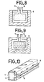
- the next phase consists in placing the cut grid in a mold, the internal configuration of which is designed such that the conductive elements 5 bear on the walls as shown in FIG. 8.
- the elastomer 4 is polymerized in the mold so as to completely cover only the close parts of the grid. The parts intended to ensure contact must themselves remain bare on their outer face.
- the support which they are made to exert on the walls of the mold at the time of the insertion of the grid in this mold has the purpose of preventing polymerization on the external faces.
- This action is reinforced by the use of a mold covered with rubber which is not adherent to the elastomer 4 used.
- FIG. 9 Another technique is described in FIG. 9.
- a parallelepiped 11 of prepolymerized elastomer is placed in the series of parallel rings formed by the lamellae. The whole is introduced into the mold 9. The molding is then completed by the polymerization of the same type of elastomer at 12.
- the parts 12 and 11 made for example of the same material have excellent adhesion, for example silicone.
- the composite according to the invention can be used in numerous connection configurations. To establish the come, it must be pressed against the rigid plans containing the tracks to be connected. These plans are either printed circuit boards or components for flat transfer such as micro-housings.
- the composite will therefore preferably be inserted into a rigid insulating element which will position it, the assembly constituting the connector.
Landscapes
- Engineering & Computer Science (AREA)
- Manufacturing & Machinery (AREA)
- Microelectronics & Electronic Packaging (AREA)
- Connections Effected By Soldering, Adhesion, Or Permanent Deformation (AREA)
- Connector Housings Or Holding Contact Members (AREA)
- Manufacturing Of Electrical Connectors (AREA)
- Coupling Device And Connection With Printed Circuit (AREA)
Abstract
Description
- L'invention concerne un élément de connexion miniature à faible pas destiné à réaliser des connexions électriques dans des systèmes électroniques.
- La miniaturisation et la complexité de plus en plus poussées des composants électroniques entrainent la multiplication des liaisons conductrices sur des surfaces restreintes.
- Les besoins de connexion des composants sur les cartes de circuit imprimé, ou des cartes entre elles, ont fait apparaître une nouvelle technologie de connecteurs basée sur l'utilisation des propriétés élastiques des élastomères.
- Un dispositif de l'art antérieur, décrit dans le brevet européen N° 0 001 471, est un connecteur dans lequel on place des parties métalliques autour d'un corps élastomère sous la forme de pistes repliées. Ce connecteur comprend un corps allongé en matériau élastomère isolant de section transversale uniforme et qui présente deux faces opposées plates et parallèles reliées entre elles d'un côté par une surface convexe. Plusieurs chemins conducteurs sont disposés sur ce corps, chacun de ces chemins comprenant une partie de contact sur chacune de ces deux faces opposées du corps et une partie s'étendant, entre ces parties de contact, le long de la surface convexe. Ces chemins conducteurs sont formés d'une lame en matériau élastomère isolant obtenue par des techniques de circuit imprimé et pliée pour former le produit désiré. Cette technique améliore la fiabilité après compression de l'élément de connexion, mais suppose des mises en oeuvre délicates du fait, d'une part, des dimensions nécessairement réduites et donc du positionnement précis des parties conductrices et, d'autre part, de la solidité de l'accrochage des parties métalliques sur l'élastomère, celles-ci n'étant pas enserrées par la matière isolante.
- La présente invention supprime ces inconvénients par une technologie qui permet une mise en oeuvre moins complexe tout en assurant une bonne liaison métal-élastomère et un haut niveau de fiabilité après compressions répétées.
- L'invention a pour objet un élément de connexion miniature à faible pas comprenant un corps en élastomère isolant de section carrée, rectangulaire, circulaire ou de tout autre forme permettant après compression d'obtenir un bon contact électrique, associé à des fils conducteurs, caractérisé en ce que ces fils sont disposés autour de ce corps sur la plus grande partie de sa circonférence et à l'intérieur de celui-ci sur le reste de manière à assurer une liaison mécanique solide entre ces fils et ce corps, ces fils émergeant de ce corps par leurs deux extrémités.
- L'invention a, en outre, pour objet un procédé de fabrication d'un tel élément de connexion.
- L'invention sera mieux comprise à la lecture de la description ci-dessous donnée à titre d'exemple non limitatif, en liaison avec les figures qui représentent :
- - les figures 1 et 2, deux vues illustrant la réalisation d'un connecteur selon l'art connu;
- - la figure 3, le connecteur selon l'invention;
- - les figures 4 à 10, des vues illustrant la réalisation du connecteur sleon l'invention.
- Les figures 1 et 2 illustrent deux étapes de réalisation d'un connecteur selon l'art connu.
- La figure 1 représente une lame 1 en matériau isolant qui comporte plusieurs chemins conducteurs, parallèles entre eux, disposés sur l'une de ses faces. Dans ce dispositif de l'art connu, cette lame est pliée, comme représenté à la figure 2, selon une médiane longitudinale, de manière à former un "U" comprenant les chemins conducteurs sur ses faces externes 3. Ce "U" est alors refermé sur lui-même, par application d'une pression entre les faces externes 3. La liaison entre les deux branches du "U" peut-être, par exemple, réalisée par échauffement, en utilisant un matériau élastomère ayant des propriétés thermo-plastiques.
- Par contre, l'invention consiste en un élément de connexion miniature à faible pas constitué de l'association de fils conducteurs et d'un corps en élastomère isolant, les fils étant positionnés de telle façon qu'ils contournent le corps isolant sur la plus grande partie de sa circonférence et pénètrent à l'intérieur sur le reste afin d'assurer une liaison mécanique solide entre ces deux parties du composite, à savoir les fils conducteurs et le corps isolant.
- Une configuration de l'invention est décrite sur la figure 3. Les lamelles conductrices 5 sont associées à l'élastomère isolant 4 qui assure à la fois l'isolement électrique des lamelles conductrices 5 et la fonction de ressort mécanique. A titre d'exemple, ces lamelles conductrices peuvent être en cuivre ou en alliage de cuivre et ce corps isolant en élastomère silicone.
- Les lamelles conductrices 5 sont à l'extérieur du corps élastomère su- trois de ses faces 21, 22 et 26. Elles sont internes au corps isolant sur la quatrième face 23 où elles n'émergent que par leurs extrémités 13. Ces lamelles métalliques, pour assurer un bon contact électrique, sont de préférence recouvertes d'une couche d'or, d'une superposition de deux couches nickel et or, d'une couche d'alliage étain-plomb, d'une couche de palladium ou de tout autre revêtement connu de l'homme de l'art, destiné à améliorer la fiabilité du contact électrique. La liaison chimique qui doit assurer leur adhésion au corps élastomère est difficile à réaliser dans le cas d'une couche d'or. Aussi, la partie entrant dans l'élastomère permet de maintenir, en le renforçant, le positionnement des conducteurs métalliques.
- A titre d'exemple, le corps élastomère peut être un parallélépipède de section carrée ayant 3 mm de côté. Les bandes métalliques peuvent avoir une largeur de 0,2 mm au pas de 0,4 mm et une épaisseur de 0,1 mm. La mise en oeuvre préférée consistera à partir d'une bande large dans laquelle on découpe soit mécaniquement, soit par attaque photo-chimique, les lamelles conductrices à leurs dimensions définitives.
- La figure 4 montre de quelle façon sont découpées les parties conductrices parallèles 5. Ces parties conductrices 5 sont maintenues parallèlement par deux bordures pleines 8 et 14 issues de la bande originale et séparées par des interstices 16. Ceci permet, d'une part, de les manipuler sans modifier leurs positions fixées une fois pour toute dès le départ et, d'autre part, d'envisager des technologies de découpe automatique en continu car cette phase du produit se présente sous forme d'une bande de grande longueur que l'on pourra bobiner.
- La seconde phase est le pliage transversal de la bande tel que représenté figure 5. Cette opération s'effectue de préférence en deux temps sur des contre-formes tel que schématisé aux figures 6 et 7 avec des directions de pliage 17 et 18. Les deux pliures, illustrées par les flèches 18, sont effectuées dans une zone de la bande où celle-ci est découpée en lamelles 5 et non dans la région des bordures 8 et 14.
- Les bordures 8 et 14 assurent la tenue mécanique et le positionnement de l'ensemble. En outre, elles relient électriquement tous les contacts, ce qui permet d'y répartir le courant électrique lors des opérations d'électrolyse.
- Les revêtements électrolytiques sont donc grandement facilités par cette configuration. Ii< peuvent être effectués avant ou après pliage dans la configuration de la figure 4 ou de la figure 5.
- A titre d'exemple, les parties métalliques seront revêtues d'une couche d'environ 2 microns de Nickel sur laquelle on déposera 1 micron d'or. La phase suivante consiste à placer la grille découpée dans un moule dont la configuration interne est conçue de telle sorte que les éléments conducteurs 5 prennent appui sur les parois comme représenté à la figure 8. L'élastomère 4 est polymérisé dans le moule de façon à n'enrober complètement que les parties rapprochées de la grille. Les parties destinées à assurer le contact doivent, elles, rester à nu sur leur face extérieure.
- L'appui qu'on leur fait exercer sur les parois du moule au moment de l'insertion de la grille dans ce moule a pour objet d'empêcher la polymérisation sur les faces externes.
- Cette action est renforcée par l'utilisation d'un moule recou- vert de caoutchouc non adhérent à l'élastomère 4 utilisé.
- Une autre technique est décrite dans la figure 9. Un parallélépipède 11 d'élastomère prépolymérisé est placé dans la série d'anneaux parallèles formés par les lamelles. Le tout est introduit dans le moule 9. Le moulage est complété ensuite par la polymérisation du même type d'élastomère en 12. Les parties 12 et 11 constituées par exemple du même matériau possèdent une excellente adhérence, par exemple en silicone.
- L'invention se présente alors selon la figure 10 et il ne reste plus qu'à couper les bordures 8 et 14 pour obtenir le produit final décrit en figure 3.
- A noter qu'il peut être avantageux de n'effectuer les traitements électrolytiques qu'avant cette dernière étape. La technologie selon l'invention offre alors la possibilité d'effectuer des revêtements uniquement sur les zones utiles, externes, ce qui est une source d'économie dans le cas de l'utilisation de métaux précieux tels que l'or.
- Le composite suivant l'invention peut être utilisé dans de nombreuses configurations de connexion. Pour établir la come il faut l'appuyer contre les plans rigides comportant les pistes a connecter. Ces plans sont soit des cartes de circuit imprime, soit des composants pour report à plat tels que les micro-boîtiers.
- Le composite sera donc de préférence inséré dans un élément rigide isolant qui le positionnera, l'ensemble constituant le connecteur.
Claims (12)
Applications Claiming Priority (2)
| Application Number | Priority Date | Filing Date | Title |
|---|---|---|---|
| FR8416873 | 1984-11-06 | ||
| FR8416873A FR2572856B1 (fr) | 1984-11-06 | 1984-11-06 | Element de connexion miniature a faible pas et procede de fabrication d'un tel element de connexion |
Publications (2)
| Publication Number | Publication Date |
|---|---|
| EP0182700A1 true EP0182700A1 (fr) | 1986-05-28 |
| EP0182700B1 EP0182700B1 (fr) | 1989-09-27 |
Family
ID=9309299
Family Applications (1)
| Application Number | Title | Priority Date | Filing Date |
|---|---|---|---|
| EP85402128A Expired EP0182700B1 (fr) | 1984-11-06 | 1985-11-05 | Elément de connexion miniature à faible pas, et procédé de fabrication d'un tel élément de connexion |
Country Status (4)
| Country | Link |
|---|---|
| US (1) | US4666226A (fr) |
| EP (1) | EP0182700B1 (fr) |
| DE (1) | DE3573359D1 (fr) |
| FR (1) | FR2572856B1 (fr) |
Cited By (5)
| Publication number | Priority date | Publication date | Assignee | Title |
|---|---|---|---|---|
| EP0269777A1 (fr) * | 1986-09-29 | 1988-06-08 | Tektronix, Inc. | Procédé de fabrication d'un élément de contact |
| EP0451363A1 (fr) * | 1990-04-02 | 1991-10-16 | Hewlett-Packard Company | Système adaptateur pour cadre de liaison automatique par rubans |
| FR2718197A1 (fr) * | 1994-03-30 | 1995-10-06 | Saitec | Dispositif de liaison par leurs tranches d'au moins deux panneaux conducteurs. |
| US5479320A (en) * | 1991-12-31 | 1995-12-26 | Compaq Computer Corporation | Board-to-board connector including an insulative spacer having a conducting surface and U-shaped contacts |
| WO2011001314A1 (fr) * | 2009-07-01 | 2011-01-06 | Koninklijke Philips Electronics, N.V. | Connecteur de jeu de conducteurs à bas coût et faible hauteur |
Families Citing this family (27)
| Publication number | Priority date | Publication date | Assignee | Title |
|---|---|---|---|---|
| US4693530A (en) * | 1986-09-29 | 1987-09-15 | Amp Incorporated | Shielded elastomeric electric connector |
| US5013248A (en) * | 1989-09-19 | 1991-05-07 | Amp Incorporated | Multicircuit connector assembly |
| DE9412068U1 (de) * | 1994-07-26 | 1994-09-15 | Festo Kg, 73734 Esslingen | Verbindungseinrichtung zu elektrischen Verbindung von Kontaktelementen |
| US5599193A (en) * | 1994-08-23 | 1997-02-04 | Augat Inc. | Resilient electrical interconnect |
| US5949029A (en) * | 1994-08-23 | 1999-09-07 | Thomas & Betts International, Inc. | Conductive elastomers and methods for fabricating the same |
| CN101174718B (zh) | 2003-03-14 | 2012-01-04 | 莫莱克斯公司 | 具有底座形状的基本传输通道链路组 |
| US8006075B2 (en) | 2009-05-21 | 2011-08-23 | Oracle America, Inc. | Dynamically allocated store queue for a multithreaded processor |
| FR3009445B1 (fr) * | 2013-07-31 | 2017-03-31 | Hypertac Sa | Organe de contact entre un support et un dispositif et connecteur electrique comprenant un tel organe de contact |
| US9399870B2 (en) | 2014-11-21 | 2016-07-26 | Building Materials Investment Corporation | Roofing shingle system and shingles for use therein |
| US9416539B2 (en) | 2014-11-21 | 2016-08-16 | Building Materials Investment Corporation | Roofing shingle system and shingles for use therein |
| USD774215S1 (en) | 2014-11-21 | 2016-12-13 | Building Materials Investment Corporation | Shingle |
| CA2912880C (fr) | 2014-11-21 | 2018-07-03 | Building Materials Investment Corporation | Systeme de bardeaux de toiture et bardeaux dudit systeme |
| USD829935S1 (en) | 2014-11-21 | 2018-10-02 | Building Materials Investment Corporation | Shingle |
| USD776303S1 (en) | 2014-11-21 | 2017-01-10 | Building Materials Investment Corporation | Shingle |
| USD827158S1 (en) | 2014-11-21 | 2018-08-28 | Building Materials Investment Corporation | Shingle |
| US9410323B1 (en) | 2015-03-13 | 2016-08-09 | Building Materials Investment Corporation | Roofing shingle system and shingles for use therein |
| USD769472S1 (en) | 2015-03-13 | 2016-10-18 | Building Materials Investment Corporation | Shingle |
| USD764076S1 (en) | 2015-03-13 | 2016-08-16 | Building Materials Investment Corporation | Shingle |
| USD766467S1 (en) | 2015-03-13 | 2016-09-13 | Building Materials Investment Corporation | Shingle |
| USD763468S1 (en) | 2015-03-26 | 2016-08-09 | Building Materials Investment Corporation | Shingle |
| USD765885S1 (en) | 2015-03-26 | 2016-09-06 | Building Materials Investment Corporation | Shingle |
| USD765887S1 (en) | 2015-03-26 | 2016-09-06 | Building Materials Investment Corporation | Shingle |
| USD765274S1 (en) | 2015-03-26 | 2016-08-30 | Building Materials Investment Corporation | Shingle |
| USD766469S1 (en) | 2015-03-26 | 2016-09-13 | Building Materials Investment Corporation | Shingle |
| USD765888S1 (en) | 2015-03-26 | 2016-09-06 | Building Materials Investment Corporation | Shingle |
| USD765273S1 (en) | 2015-03-26 | 2016-08-30 | Building Materials Investment Corporation | Shingle |
| USD765886S1 (en) | 2015-03-26 | 2016-09-06 | Building Materials Investment Corporation | Shingle |
Citations (5)
| Publication number | Priority date | Publication date | Assignee | Title |
|---|---|---|---|---|
| FR2192437A1 (fr) * | 1972-07-10 | 1974-02-08 | Radiotechnique Compelec | |
| US3795884A (en) * | 1973-03-06 | 1974-03-05 | Amp Inc | Electrical connector formed from coil spring |
| DE2651186A1 (de) * | 1976-11-10 | 1978-05-18 | Kabel Metallwerke Ghh | Vorrichtung zur elektrisch leitenden verbindung zweier bauteile |
| EP0001477A1 (fr) * | 1977-09-24 | 1979-04-18 | AMP INCORPORATED (a New Jersey corporation) | Méthode de fabrication d'un connecteur électrique multicontact |
| US4395084A (en) * | 1981-07-06 | 1983-07-26 | Teledyne Industries, Inc. | Electrical socket for leadless integrated circuit packages |
Family Cites Families (1)
| Publication number | Priority date | Publication date | Assignee | Title |
|---|---|---|---|---|
| US3991463A (en) * | 1975-05-19 | 1976-11-16 | Chomerics, Inc. | Method of forming an interconnector |
-
1984
- 1984-11-06 FR FR8416873A patent/FR2572856B1/fr not_active Expired
-
1985
- 1985-11-04 US US06/795,073 patent/US4666226A/en not_active Expired - Fee Related
- 1985-11-05 DE DE8585402128T patent/DE3573359D1/de not_active Expired
- 1985-11-05 EP EP85402128A patent/EP0182700B1/fr not_active Expired
Patent Citations (5)
| Publication number | Priority date | Publication date | Assignee | Title |
|---|---|---|---|---|
| FR2192437A1 (fr) * | 1972-07-10 | 1974-02-08 | Radiotechnique Compelec | |
| US3795884A (en) * | 1973-03-06 | 1974-03-05 | Amp Inc | Electrical connector formed from coil spring |
| DE2651186A1 (de) * | 1976-11-10 | 1978-05-18 | Kabel Metallwerke Ghh | Vorrichtung zur elektrisch leitenden verbindung zweier bauteile |
| EP0001477A1 (fr) * | 1977-09-24 | 1979-04-18 | AMP INCORPORATED (a New Jersey corporation) | Méthode de fabrication d'un connecteur électrique multicontact |
| US4395084A (en) * | 1981-07-06 | 1983-07-26 | Teledyne Industries, Inc. | Electrical socket for leadless integrated circuit packages |
Non-Patent Citations (1)
| Title |
|---|
| PROCEEDINGS OF THE S.I.D., vol. 21, no. 2, 1980, pages 157-164, Los Angeles, US; L.S. BUCHOFF: "Metal-elastomeric display connectors" * |
Cited By (9)
| Publication number | Priority date | Publication date | Assignee | Title |
|---|---|---|---|---|
| EP0269777A1 (fr) * | 1986-09-29 | 1988-06-08 | Tektronix, Inc. | Procédé de fabrication d'un élément de contact |
| EP0451363A1 (fr) * | 1990-04-02 | 1991-10-16 | Hewlett-Packard Company | Système adaptateur pour cadre de liaison automatique par rubans |
| US5099392A (en) * | 1990-04-02 | 1992-03-24 | Hewlett-Packard Company | Tape-automated bonding frame adapter system |
| US5479320A (en) * | 1991-12-31 | 1995-12-26 | Compaq Computer Corporation | Board-to-board connector including an insulative spacer having a conducting surface and U-shaped contacts |
| US5685073A (en) * | 1991-12-31 | 1997-11-11 | Compaq Computer Corporation | Method of manufacturing board-to-board connector |
| FR2718197A1 (fr) * | 1994-03-30 | 1995-10-06 | Saitec | Dispositif de liaison par leurs tranches d'au moins deux panneaux conducteurs. |
| WO2011001314A1 (fr) * | 2009-07-01 | 2011-01-06 | Koninklijke Philips Electronics, N.V. | Connecteur de jeu de conducteurs à bas coût et faible hauteur |
| RU2559816C2 (ru) * | 2009-07-01 | 2015-08-10 | Конинклейке Филипс Электроникс Н.В. | Недорогой компактный разъем для комплекта выводов |
| US10096926B2 (en) | 2009-07-01 | 2018-10-09 | Koninklijke Philips N.V. | Low cost-low profile lead set connector |
Also Published As
| Publication number | Publication date |
|---|---|
| US4666226A (en) | 1987-05-19 |
| FR2572856A1 (fr) | 1986-05-09 |
| DE3573359D1 (en) | 1989-11-02 |
| FR2572856B1 (fr) | 1988-01-08 |
| EP0182700B1 (fr) | 1989-09-27 |
Similar Documents
| Publication | Publication Date | Title |
|---|---|---|
| EP0182700B1 (fr) | Elément de connexion miniature à faible pas, et procédé de fabrication d'un tel élément de connexion | |
| EP0298800B1 (fr) | nrocédé de fabrication d'un ensemble multi-couches utilisable pour la réalisation de l'assemblage de générateurs électrochimiques au lithium en couche mince à électrolyte solide polymère | |
| FR2557385A1 (fr) | Connecteur electrique multipolaire et son procede de fabrication | |
| CN111864257B (zh) | 全固态电池及全固态电池的制造方法 | |
| EP0500168A1 (fr) | Procédé de fabrication d'un module électronique pour carte à mémoire et module électronique ainsi obtenu | |
| EP1586122B1 (fr) | Module photovoltaique comportant des bornes de connexion avec l'exterieur | |
| EP1008176B1 (fr) | Procede de fabrication d'un film conducteur anisotrope a inserts conducteurs | |
| EP0205360B1 (fr) | Bande de connexion pour la fabrication de composants électriques à report direct et procédé de fabrication de ces composants | |
| FR2629660A1 (fr) | Capsule piezoelectrique a pinces de connection electrique laterales | |
| EP0789423B1 (fr) | Procédé de réalisation d'une connexion électrique par collage d'une cosse rigide sur une piste conductrice, cosse rigide pour la mise en oeuvre du procédé et plaque chauffante comportant la cosse | |
| EP0305267B1 (fr) | Procédé pour la réalisation d'un ensemble de motifs électriquement conducteurs sur une surface isolante de forme complexe | |
| FR2541828A1 (fr) | Dispositif de connexion electrique entre deux cartes de circuits imprimes et procede de connexion de deux cartes de circuits imprimes a l'aide d'un tel dispositif | |
| EP1964203B1 (fr) | Procédé de fabrication d'une pile à combustible avec collecteurs de courant integrés à l'électrolyte solide | |
| FR2602907A1 (fr) | Anode de condensateur, procede de fabrication de cette anode, et condensateur la comportant | |
| EP0195871A1 (fr) | Connecteur électrique multipolaire et son procédé de fabrication | |
| WO2004075304A1 (fr) | Procede de realisation d’un module photovoltaique et module photovoltaique realise par ce procede | |
| FR2818170A1 (fr) | Procede de fabrication d'une sonde acoustique multielements utilisant un film polymere metallise et ablate comme plan de masse | |
| FR2529428A1 (fr) | Procede d'enrobage et de prise de connexion pour composant electronique, notamment pour condensateur a electrolyte solide a anode d'aluminium, et composant enrobe ainsi obtenu. | |
| EP0226498B1 (fr) | Organe lamellaire de liaison électrique de deux circuits | |
| FR2542923A1 (fr) | Composant electronique polarise et son procede de fabrication | |
| FR2601826A1 (fr) | Bande souple de raccordement electrique | |
| EP2750228A1 (fr) | Connecteur pour cellules de pile à combustible et procédé de mise en oeuvre | |
| EP0168287B1 (fr) | Procédé pour la réalisation d'un circuit imprimé et circuit imprimé obtenu par la mise en oeuvre dudit procédé | |
| CA2028332A1 (fr) | Connecteur miniature pour cable plat blinde et organes de contact le constituant | |
| FR2789229A1 (fr) | Electrode spiralee a support tridimensionnel |
Legal Events
| Date | Code | Title | Description |
|---|---|---|---|
| PUAI | Public reference made under article 153(3) epc to a published international application that has entered the european phase |
Free format text: ORIGINAL CODE: 0009012 |
|
| AK | Designated contracting states |
Kind code of ref document: A1 Designated state(s): DE GB IT |
|
| 17P | Request for examination filed |
Effective date: 19861112 |
|
| 17Q | First examination report despatched |
Effective date: 19880323 |
|
| GRAA | (expected) grant |
Free format text: ORIGINAL CODE: 0009210 |
|
| ITF | It: translation for a ep patent filed | ||
| AK | Designated contracting states |
Kind code of ref document: B1 Designated state(s): DE GB IT |
|
| REF | Corresponds to: |
Ref document number: 3573359 Country of ref document: DE Date of ref document: 19891102 |
|
| GBT | Gb: translation of ep patent filed (gb section 77(6)(a)/1977) | ||
| PLBE | No opposition filed within time limit |
Free format text: ORIGINAL CODE: 0009261 |
|
| STAA | Information on the status of an ep patent application or granted ep patent |
Free format text: STATUS: NO OPPOSITION FILED WITHIN TIME LIMIT |
|
| 26N | No opposition filed | ||
| PGFP | Annual fee paid to national office [announced via postgrant information from national office to epo] |
Ref country code: GB Payment date: 19901017 Year of fee payment: 6 |
|
| ITTA | It: last paid annual fee | ||
| PGFP | Annual fee paid to national office [announced via postgrant information from national office to epo] |
Ref country code: DE Payment date: 19901130 Year of fee payment: 6 |
|
| PG25 | Lapsed in a contracting state [announced via postgrant information from national office to epo] |
Ref country code: GB Effective date: 19911105 |
|
| GBPC | Gb: european patent ceased through non-payment of renewal fee | ||
| PG25 | Lapsed in a contracting state [announced via postgrant information from national office to epo] |
Ref country code: DE Effective date: 19920801 |