EP0182700A1 - Miniaturverbindungselement mit schwachem Schritt und Verfahren zur Herstellung eines solchen Verbindungselementes - Google Patents
Miniaturverbindungselement mit schwachem Schritt und Verfahren zur Herstellung eines solchen Verbindungselementes Download PDFInfo
- Publication number
- EP0182700A1 EP0182700A1 EP85402128A EP85402128A EP0182700A1 EP 0182700 A1 EP0182700 A1 EP 0182700A1 EP 85402128 A EP85402128 A EP 85402128A EP 85402128 A EP85402128 A EP 85402128A EP 0182700 A1 EP0182700 A1 EP 0182700A1
- Authority
- EP
- European Patent Office
- Prior art keywords
- strip
- wires
- mold
- connection element
- elastomer
- Prior art date
- Legal status (The legal status is an assumption and is not a legal conclusion. Google has not performed a legal analysis and makes no representation as to the accuracy of the status listed.)
- Granted
Links
Images


Classifications
-
- H—ELECTRICITY
- H01—ELECTRIC ELEMENTS
- H01R—ELECTRICALLY-CONDUCTIVE CONNECTIONS; STRUCTURAL ASSOCIATIONS OF A PLURALITY OF MUTUALLY-INSULATED ELECTRICAL CONNECTING ELEMENTS; COUPLING DEVICES; CURRENT COLLECTORS
- H01R43/00—Apparatus or processes specially adapted for manufacturing, assembling, maintaining, or repairing of line connectors or current collectors or for joining electric conductors
- H01R43/007—Apparatus or processes specially adapted for manufacturing, assembling, maintaining, or repairing of line connectors or current collectors or for joining electric conductors for elastomeric connecting elements
-
- H—ELECTRICITY
- H01—ELECTRIC ELEMENTS
- H01R—ELECTRICALLY-CONDUCTIVE CONNECTIONS; STRUCTURAL ASSOCIATIONS OF A PLURALITY OF MUTUALLY-INSULATED ELECTRICAL CONNECTING ELEMENTS; COUPLING DEVICES; CURRENT COLLECTORS
- H01R12/00—Structural associations of a plurality of mutually-insulated electrical connecting elements, specially adapted for printed circuits, e.g. printed circuit boards [PCB], flat or ribbon cables, or like generally planar structures, e.g. terminal strips, terminal blocks; Coupling devices specially adapted for printed circuits, flat or ribbon cables, or like generally planar structures; Terminals specially adapted for contact with, or insertion into, printed circuits, flat or ribbon cables, or like generally planar structures
- H01R12/70—Coupling devices
- H01R12/71—Coupling devices for rigid printing circuits or like structures
- H01R12/712—Coupling devices for rigid printing circuits or like structures co-operating with the surface of the printed circuit or with a coupling device exclusively provided on the surface of the printed circuit
- H01R12/714—Coupling devices for rigid printing circuits or like structures co-operating with the surface of the printed circuit or with a coupling device exclusively provided on the surface of the printed circuit with contacts abutting directly the printed circuit; Button contacts therefore provided on the printed circuit
-
- H—ELECTRICITY
- H01—ELECTRIC ELEMENTS
- H01R—ELECTRICALLY-CONDUCTIVE CONNECTIONS; STRUCTURAL ASSOCIATIONS OF A PLURALITY OF MUTUALLY-INSULATED ELECTRICAL CONNECTING ELEMENTS; COUPLING DEVICES; CURRENT COLLECTORS
- H01R13/00—Details of coupling devices of the kinds covered by groups H01R12/70 or H01R24/00 - H01R33/00
- H01R13/02—Contact members
- H01R13/22—Contacts for co-operating by abutting
-
- H—ELECTRICITY
- H05—ELECTRIC TECHNIQUES NOT OTHERWISE PROVIDED FOR
- H05K—PRINTED CIRCUITS; CASINGS OR CONSTRUCTIONAL DETAILS OF ELECTRIC APPARATUS; MANUFACTURE OF ASSEMBLAGES OF ELECTRICAL COMPONENTS
- H05K7/00—Constructional details common to different types of electric apparatus
- H05K7/02—Arrangements of circuit components or wiring on supporting structure
- H05K7/10—Plug-in assemblages of components, e.g. IC sockets
- H05K7/1053—Plug-in assemblages of components, e.g. IC sockets having interior leads
- H05K7/1061—Plug-in assemblages of components, e.g. IC sockets having interior leads co-operating by abutting
-
- Y—GENERAL TAGGING OF NEW TECHNOLOGICAL DEVELOPMENTS; GENERAL TAGGING OF CROSS-SECTIONAL TECHNOLOGIES SPANNING OVER SEVERAL SECTIONS OF THE IPC; TECHNICAL SUBJECTS COVERED BY FORMER USPC CROSS-REFERENCE ART COLLECTIONS [XRACs] AND DIGESTS
- Y10—TECHNICAL SUBJECTS COVERED BY FORMER USPC
- Y10T—TECHNICAL SUBJECTS COVERED BY FORMER US CLASSIFICATION
- Y10T29/00—Metal working
- Y10T29/49—Method of mechanical manufacture
- Y10T29/49002—Electrical device making
- Y10T29/49117—Conductor or circuit manufacturing
- Y10T29/49204—Contact or terminal manufacturing
- Y10T29/49208—Contact or terminal manufacturing by assembling plural parts
- Y10T29/4922—Contact or terminal manufacturing by assembling plural parts with molding of insulation
Definitions
- the invention relates to a low pitch miniature connection element for making electrical connections in electronic systems.
- connection needs of the components on the printed circuit boards, or of the boards together, have given rise to a new technology of connectors based on the use of the elastic properties of elastomers.
- a device of the prior art is a connector in which metal parts are placed around an elastomer body in the form of folded tracks.
- This connector comprises an elongated body of insulating elastomeric material of uniform cross section and which has two opposite flat and parallel faces joined together on one side by a convex surface.
- Several conductive paths are arranged on this body, each of these paths comprising a contact part on each of these two opposite faces of the body and a part extending, between these contact parts, along the convex surface.
- These conductive paths are formed of a strip of insulating elastomeric material obtained by printed circuit techniques and folded to form the desired product.
- connection element improves the reliability after compression of the connection element, but assumes delicate implementations because, on the one hand, of the necessarily reduced dimensions and therefore of the precise positioning of the conductive parts and, on the other hand, of the solidity of the attachment of the metal parts to the elastomer, these not being enclosed by the insulating material.
- the present invention eliminates these drawbacks by a technology which allows a less complex implementation while ensuring a good metal-elastomer bond and a high level of reliability after repeated compressions.
- the subject of the invention is a low-pitch miniature connection element comprising an insulating elastomer body of square, rectangular, circular or any other shape allowing compression to obtain good electrical contact, associated with conductive wires, characterized in that these wires are arranged around this body over the greater part of its circumference and inside of it over the rest so as to ensure a solid mechanical connection between these wires and this body, these wires emerging from this body by their two ends.
- the invention further relates to a method of manufacturing such a connection element.
- Figures 1 and 2 illustrate two stages of producing a connector according to the prior art.
- Figure 1 shows a blade 1 of insulating material which has several conductive paths, parallel to each other, arranged on one of its faces.
- this blade is folded, as shown in FIG. 2, along a longitudinal median, so as to form a "U” comprising the conductive paths on its external faces 3.
- This "U” is then closed on itself, by applying pressure between the external faces 3.
- the connection between the two branches of the "U” may, for example, be made by heating, using an elastomeric material having thermo-plastic properties .
- the invention consists of a miniature connection element with a small pitch consisting of the association of conducting wires and an insulating elastomer body, the wires being positioned in such a way that they bypass the insulating body on the most large part of its circumference and penetrate inside on the rest in order to ensure a solid mechanical connection between these two parts of the composite, namely the conductive wires and the insulating body.
- FIG. 3 A configuration of the invention is described in FIG. 3.
- the conductive strips 5 are associated with the insulating elastomer 4 which ensures both the electrical isolation of the conductive strips 5 and the function of mechanical spring.
- these conductive strips can be made of copper or of a copper alloy and this insulating body of silicone elastomer.
- the conductive strips 5 are outside the elastomer body on three of its faces 21, 22 and 26. They are internal to the insulating body on the fourth face 23 where they only emerge at their ends 13.
- These metal strips to ensure good electrical contact, are preferably covered with a layer of gold, a superposition of two layers of nickel and gold, a layer of tin-lead alloy, a layer of palladium or any another coating known to those skilled in the art, intended to improve the reliability of the electrical contact.
- the chemical bond which must ensure their adhesion to the elastomer body is difficult to achieve in the case of a layer of gold. Also, the part entering the elastomer makes it possible to maintain, by strengthening it, the positioning of the metallic conductors.
- the elastomer body may be a parallelepiped of square section having 3 mm on a side.
- the metal strips can have a width of 0.2 mm with a pitch of 0.4 mm and a thickness of 0.1 mm.
- the preferred implementation will consist of starting from a wide strip in which one cuts either mechanically, or by photochemical attack, the conductive lamellae to their final dimensions.
- FIG. 4 shows how the parallel conductive parts 5 are cut out. These conductive parts 5 are held in parallel by two solid edges 8 and 14 coming from the original strip and separated by interstices 16. This makes it possible, on the one hand, to handle them without changing their fixed positions once and for all from the start and, on the other hand, to consider continuous automatic cutting technologies because this phase of the product is in the form of a strip of great length than the we can wind.
- the second phase is the transverse folding of the strip as shown in FIG. 5.
- This operation is preferably carried out in two stages on counterforms as shown diagrammatically in FIGS. 6 and 7 with folding directions 17 and 18. Both folds, illustrated by the arrows 18, are carried out in an area of the strip where the latter is cut into strips 5 and not in the region of the edges 8 and 14.
- edges 8 and 14 ensure the mechanical strength and positioning of the assembly. In addition, they electrically connect all the contacts, which makes it possible to distribute the electric current there during electrolysis operations.
- the electrolytic coatings are therefore greatly facilitated by this configuration. They can be carried out before or after folding in the configuration of FIG. 4 or of FIG. 5.
- the metal parts will be coated with a layer of about 2 microns of nickel on which 1 micron of gold will be deposited.
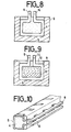
- the next phase consists in placing the cut grid in a mold, the internal configuration of which is designed such that the conductive elements 5 bear on the walls as shown in FIG. 8.
- the elastomer 4 is polymerized in the mold so as to completely cover only the close parts of the grid. The parts intended to ensure contact must themselves remain bare on their outer face.
- the support which they are made to exert on the walls of the mold at the time of the insertion of the grid in this mold has the purpose of preventing polymerization on the external faces.
- This action is reinforced by the use of a mold covered with rubber which is not adherent to the elastomer 4 used.
- FIG. 9 Another technique is described in FIG. 9.
- a parallelepiped 11 of prepolymerized elastomer is placed in the series of parallel rings formed by the lamellae. The whole is introduced into the mold 9. The molding is then completed by the polymerization of the same type of elastomer at 12.
- the parts 12 and 11 made for example of the same material have excellent adhesion, for example silicone.
- the composite according to the invention can be used in numerous connection configurations. To establish the come, it must be pressed against the rigid plans containing the tracks to be connected. These plans are either printed circuit boards or components for flat transfer such as micro-housings.
- the composite will therefore preferably be inserted into a rigid insulating element which will position it, the assembly constituting the connector.
Landscapes
- Engineering & Computer Science (AREA)
- Manufacturing & Machinery (AREA)
- Microelectronics & Electronic Packaging (AREA)
- Connections Effected By Soldering, Adhesion, Or Permanent Deformation (AREA)
- Connector Housings Or Holding Contact Members (AREA)
- Manufacturing Of Electrical Connectors (AREA)
- Coupling Device And Connection With Printed Circuit (AREA)
Applications Claiming Priority (2)
| Application Number | Priority Date | Filing Date | Title |
|---|---|---|---|
| FR8416873A FR2572856B1 (fr) | 1984-11-06 | 1984-11-06 | Element de connexion miniature a faible pas et procede de fabrication d'un tel element de connexion |
| FR8416873 | 1984-11-06 |
Publications (2)
| Publication Number | Publication Date |
|---|---|
| EP0182700A1 true EP0182700A1 (de) | 1986-05-28 |
| EP0182700B1 EP0182700B1 (de) | 1989-09-27 |
Family
ID=9309299
Family Applications (1)
| Application Number | Title | Priority Date | Filing Date |
|---|---|---|---|
| EP85402128A Expired EP0182700B1 (de) | 1984-11-06 | 1985-11-05 | Miniaturverbindungselement mit schwachem Schritt und Verfahren zur Herstellung eines solchen Verbindungselementes |
Country Status (4)
| Country | Link |
|---|---|
| US (1) | US4666226A (de) |
| EP (1) | EP0182700B1 (de) |
| DE (1) | DE3573359D1 (de) |
| FR (1) | FR2572856B1 (de) |
Cited By (5)
| Publication number | Priority date | Publication date | Assignee | Title |
|---|---|---|---|---|
| EP0269777A1 (de) * | 1986-09-29 | 1988-06-08 | Tektronix, Inc. | Verfahren zum Herstellen eines Kontaktelementes |
| EP0451363A1 (de) * | 1990-04-02 | 1991-10-16 | Hewlett-Packard Company | Filmträgerbandverbinderrahmenadaptersystem |
| FR2718197A1 (fr) * | 1994-03-30 | 1995-10-06 | Saitec | Dispositif de liaison par leurs tranches d'au moins deux panneaux conducteurs. |
| US5479320A (en) * | 1991-12-31 | 1995-12-26 | Compaq Computer Corporation | Board-to-board connector including an insulative spacer having a conducting surface and U-shaped contacts |
| WO2011001314A1 (en) * | 2009-07-01 | 2011-01-06 | Koninklijke Philips Electronics, N.V. | Low cost-low profile lead set connector |
Families Citing this family (27)
| Publication number | Priority date | Publication date | Assignee | Title |
|---|---|---|---|---|
| US4693530A (en) * | 1986-09-29 | 1987-09-15 | Amp Incorporated | Shielded elastomeric electric connector |
| US5013248A (en) * | 1989-09-19 | 1991-05-07 | Amp Incorporated | Multicircuit connector assembly |
| DE9412068U1 (de) * | 1994-07-26 | 1994-09-15 | Festo Kg, 73734 Esslingen | Verbindungseinrichtung zu elektrischen Verbindung von Kontaktelementen |
| US5599193A (en) * | 1994-08-23 | 1997-02-04 | Augat Inc. | Resilient electrical interconnect |
| US5949029A (en) * | 1994-08-23 | 1999-09-07 | Thomas & Betts International, Inc. | Conductive elastomers and methods for fabricating the same |
| CN101174718B (zh) * | 2003-03-14 | 2012-01-04 | 莫莱克斯公司 | 具有底座形状的基本传输通道链路组 |
| US8006075B2 (en) | 2009-05-21 | 2011-08-23 | Oracle America, Inc. | Dynamically allocated store queue for a multithreaded processor |
| FR3009445B1 (fr) * | 2013-07-31 | 2017-03-31 | Hypertac Sa | Organe de contact entre un support et un dispositif et connecteur electrique comprenant un tel organe de contact |
| US9416539B2 (en) | 2014-11-21 | 2016-08-16 | Building Materials Investment Corporation | Roofing shingle system and shingles for use therein |
| US9399870B2 (en) | 2014-11-21 | 2016-07-26 | Building Materials Investment Corporation | Roofing shingle system and shingles for use therein |
| USD829935S1 (en) | 2014-11-21 | 2018-10-02 | Building Materials Investment Corporation | Shingle |
| USD774215S1 (en) | 2014-11-21 | 2016-12-13 | Building Materials Investment Corporation | Shingle |
| US9399871B2 (en) | 2014-11-21 | 2016-07-26 | Building Materials Investment Corporation | Roofing shingle system and shingles for use therein |
| USD776303S1 (en) | 2014-11-21 | 2017-01-10 | Building Materials Investment Corporation | Shingle |
| USD827158S1 (en) | 2014-11-21 | 2018-08-28 | Building Materials Investment Corporation | Shingle |
| USD769472S1 (en) | 2015-03-13 | 2016-10-18 | Building Materials Investment Corporation | Shingle |
| US9410323B1 (en) | 2015-03-13 | 2016-08-09 | Building Materials Investment Corporation | Roofing shingle system and shingles for use therein |
| USD764076S1 (en) | 2015-03-13 | 2016-08-16 | Building Materials Investment Corporation | Shingle |
| USD766467S1 (en) | 2015-03-13 | 2016-09-13 | Building Materials Investment Corporation | Shingle |
| USD766469S1 (en) | 2015-03-26 | 2016-09-13 | Building Materials Investment Corporation | Shingle |
| USD765887S1 (en) | 2015-03-26 | 2016-09-06 | Building Materials Investment Corporation | Shingle |
| USD765885S1 (en) | 2015-03-26 | 2016-09-06 | Building Materials Investment Corporation | Shingle |
| USD765273S1 (en) | 2015-03-26 | 2016-08-30 | Building Materials Investment Corporation | Shingle |
| USD765274S1 (en) | 2015-03-26 | 2016-08-30 | Building Materials Investment Corporation | Shingle |
| USD765888S1 (en) | 2015-03-26 | 2016-09-06 | Building Materials Investment Corporation | Shingle |
| USD763468S1 (en) | 2015-03-26 | 2016-08-09 | Building Materials Investment Corporation | Shingle |
| USD765886S1 (en) | 2015-03-26 | 2016-09-06 | Building Materials Investment Corporation | Shingle |
Citations (5)
| Publication number | Priority date | Publication date | Assignee | Title |
|---|---|---|---|---|
| FR2192437A1 (de) * | 1972-07-10 | 1974-02-08 | Radiotechnique Compelec | |
| US3795884A (en) * | 1973-03-06 | 1974-03-05 | Amp Inc | Electrical connector formed from coil spring |
| DE2651186A1 (de) * | 1976-11-10 | 1978-05-18 | Kabel Metallwerke Ghh | Vorrichtung zur elektrisch leitenden verbindung zweier bauteile |
| EP0001477A1 (de) * | 1977-09-24 | 1979-04-18 | AMP INCORPORATED (a New Jersey corporation) | Verfahren zur Herstellung eines elektrischer Vielfach-Steckverbinders |
| US4395084A (en) * | 1981-07-06 | 1983-07-26 | Teledyne Industries, Inc. | Electrical socket for leadless integrated circuit packages |
Family Cites Families (1)
| Publication number | Priority date | Publication date | Assignee | Title |
|---|---|---|---|---|
| US3991463A (en) * | 1975-05-19 | 1976-11-16 | Chomerics, Inc. | Method of forming an interconnector |
-
1984
- 1984-11-06 FR FR8416873A patent/FR2572856B1/fr not_active Expired
-
1985
- 1985-11-04 US US06/795,073 patent/US4666226A/en not_active Expired - Fee Related
- 1985-11-05 EP EP85402128A patent/EP0182700B1/de not_active Expired
- 1985-11-05 DE DE8585402128T patent/DE3573359D1/de not_active Expired
Patent Citations (5)
| Publication number | Priority date | Publication date | Assignee | Title |
|---|---|---|---|---|
| FR2192437A1 (de) * | 1972-07-10 | 1974-02-08 | Radiotechnique Compelec | |
| US3795884A (en) * | 1973-03-06 | 1974-03-05 | Amp Inc | Electrical connector formed from coil spring |
| DE2651186A1 (de) * | 1976-11-10 | 1978-05-18 | Kabel Metallwerke Ghh | Vorrichtung zur elektrisch leitenden verbindung zweier bauteile |
| EP0001477A1 (de) * | 1977-09-24 | 1979-04-18 | AMP INCORPORATED (a New Jersey corporation) | Verfahren zur Herstellung eines elektrischer Vielfach-Steckverbinders |
| US4395084A (en) * | 1981-07-06 | 1983-07-26 | Teledyne Industries, Inc. | Electrical socket for leadless integrated circuit packages |
Non-Patent Citations (1)
| Title |
|---|
| PROCEEDINGS OF THE S.I.D., vol. 21, no. 2, 1980, pages 157-164, Los Angeles, US; L.S. BUCHOFF: "Metal-elastomeric display connectors" * |
Cited By (9)
| Publication number | Priority date | Publication date | Assignee | Title |
|---|---|---|---|---|
| EP0269777A1 (de) * | 1986-09-29 | 1988-06-08 | Tektronix, Inc. | Verfahren zum Herstellen eines Kontaktelementes |
| EP0451363A1 (de) * | 1990-04-02 | 1991-10-16 | Hewlett-Packard Company | Filmträgerbandverbinderrahmenadaptersystem |
| US5099392A (en) * | 1990-04-02 | 1992-03-24 | Hewlett-Packard Company | Tape-automated bonding frame adapter system |
| US5479320A (en) * | 1991-12-31 | 1995-12-26 | Compaq Computer Corporation | Board-to-board connector including an insulative spacer having a conducting surface and U-shaped contacts |
| US5685073A (en) * | 1991-12-31 | 1997-11-11 | Compaq Computer Corporation | Method of manufacturing board-to-board connector |
| FR2718197A1 (fr) * | 1994-03-30 | 1995-10-06 | Saitec | Dispositif de liaison par leurs tranches d'au moins deux panneaux conducteurs. |
| WO2011001314A1 (en) * | 2009-07-01 | 2011-01-06 | Koninklijke Philips Electronics, N.V. | Low cost-low profile lead set connector |
| RU2559816C2 (ru) * | 2009-07-01 | 2015-08-10 | Конинклейке Филипс Электроникс Н.В. | Недорогой компактный разъем для комплекта выводов |
| US10096926B2 (en) | 2009-07-01 | 2018-10-09 | Koninklijke Philips N.V. | Low cost-low profile lead set connector |
Also Published As
| Publication number | Publication date |
|---|---|
| FR2572856B1 (fr) | 1988-01-08 |
| EP0182700B1 (de) | 1989-09-27 |
| DE3573359D1 (en) | 1989-11-02 |
| US4666226A (en) | 1987-05-19 |
| FR2572856A1 (fr) | 1986-05-09 |
Similar Documents
| Publication | Publication Date | Title |
|---|---|---|
| EP0182700B1 (de) | Miniaturverbindungselement mit schwachem Schritt und Verfahren zur Herstellung eines solchen Verbindungselementes | |
| EP0298800B1 (de) | Verfahren zur Herstellung einer Mehrschichtstruktur zur Herstellung von als Dünnschicht ausgebildeten elektrochemischen Generatoren mit einer Lithiumdünnschicht und einem Feststoff-Polymerelektrolyten | |
| FR2557385A1 (fr) | Connecteur electrique multipolaire et son procede de fabrication | |
| CN111864257B (zh) | 全固态电池及全固态电池的制造方法 | |
| EP0500168A1 (de) | Verfahren zur Herstellung eines elektronischen Moduls für eine Speicherkarte und elektronisches, nach diesem Verfahren hergestelltes Modul | |
| EP1586122B1 (de) | Photovoltaisches modul mit aussenanschlussklemmen | |
| EP0205360B1 (de) | Anschlussband für die Herstellung von elektrischen Bauelementen in Chipbauweise und Verfahren zur Herstellung dieser Bauelemente | |
| FR2530369A1 (fr) | Barre omnibus lamifiee perfectionnee et son procede de fabrication | |
| EP1008176A1 (de) | Herstellungsverfahren für einen anisotropischen leiterfilm mit leitenden einsatzstücken | |
| FR2629660A1 (fr) | Capsule piezoelectrique a pinces de connection electrique laterales | |
| FR2647587A1 (fr) | Procede d'application de pistes conductrices sur l'exterieur d'une piece en ceramique, procede de fabrication d'un condensateur et condensateur ceramique multicouche | |
| EP0789423B1 (de) | Verfahren zur Herstellung einer elektrischen Verbindung durch Kleben eines starren Anschlusselements auf eine Leiterbahn, ein starres Anschlusselement zur Durchführung dieses Verfahrens und eine dieses Anschlusselement tragende Heizplatte | |
| US20040182837A1 (en) | Stripping insulation from flat cables | |
| EP0305267B1 (de) | Herstellungsverfahren der Gesamtheit von elektrisch leitenden Mustern auf einer Fläche aus isolierendem Material von komplexer Form | |
| EP1964203B1 (de) | Verfahren zur herstellung einer brennstoffzelle mit im festelektrolyt integrierten stromkollektoren | |
| EP0195871A1 (de) | Mehrpoliger, elektrischer Steckverbinder und sein Herstellungsverfahren | |
| EP0120754B1 (de) | Polarisierte elektronische Vorrichtung und Verfahren zu ihrer Herstellung | |
| WO2004075304A1 (fr) | Procede de realisation d’un module photovoltaique et module photovoltaique realise par ce procede | |
| FR2563948A1 (fr) | Perfectionnements aux connecteurs electriques et aux procedes de fabrication de ceux-ci | |
| FR2818170A1 (fr) | Procede de fabrication d'une sonde acoustique multielements utilisant un film polymere metallise et ablate comme plan de masse | |
| FR2529428A1 (fr) | Procede d'enrobage et de prise de connexion pour composant electronique, notamment pour condensateur a electrolyte solide a anode d'aluminium, et composant enrobe ainsi obtenu. | |
| EP0226498B1 (de) | Lamellenförmiges elektrisches Verbindungsorgan von zwei Schaltungen | |
| FR2693845A1 (fr) | Connecteur électrique blindé perfectionné. | |
| FR2601826A1 (fr) | Bande souple de raccordement electrique | |
| EP2750228A1 (de) | Steckverbinder für Brennstoffzellen, und entsprechendes Umsetzungsverfahren |
Legal Events
| Date | Code | Title | Description |
|---|---|---|---|
| PUAI | Public reference made under article 153(3) epc to a published international application that has entered the european phase |
Free format text: ORIGINAL CODE: 0009012 |
|
| AK | Designated contracting states |
Kind code of ref document: A1 Designated state(s): DE GB IT |
|
| 17P | Request for examination filed |
Effective date: 19861112 |
|
| 17Q | First examination report despatched |
Effective date: 19880323 |
|
| GRAA | (expected) grant |
Free format text: ORIGINAL CODE: 0009210 |
|
| ITF | It: translation for a ep patent filed | ||
| AK | Designated contracting states |
Kind code of ref document: B1 Designated state(s): DE GB IT |
|
| REF | Corresponds to: |
Ref document number: 3573359 Country of ref document: DE Date of ref document: 19891102 |
|
| GBT | Gb: translation of ep patent filed (gb section 77(6)(a)/1977) | ||
| PLBE | No opposition filed within time limit |
Free format text: ORIGINAL CODE: 0009261 |
|
| STAA | Information on the status of an ep patent application or granted ep patent |
Free format text: STATUS: NO OPPOSITION FILED WITHIN TIME LIMIT |
|
| 26N | No opposition filed | ||
| PGFP | Annual fee paid to national office [announced via postgrant information from national office to epo] |
Ref country code: GB Payment date: 19901017 Year of fee payment: 6 |
|
| ITTA | It: last paid annual fee | ||
| PGFP | Annual fee paid to national office [announced via postgrant information from national office to epo] |
Ref country code: DE Payment date: 19901130 Year of fee payment: 6 |
|
| PG25 | Lapsed in a contracting state [announced via postgrant information from national office to epo] |
Ref country code: GB Effective date: 19911105 |
|
| GBPC | Gb: european patent ceased through non-payment of renewal fee | ||
| PG25 | Lapsed in a contracting state [announced via postgrant information from national office to epo] |
Ref country code: DE Effective date: 19920801 |