EP0182736A2 - Pièce de connexion pour raccorder des conducteurs électriques ronds - Google Patents
Pièce de connexion pour raccorder des conducteurs électriques ronds Download PDFInfo
- Publication number
- EP0182736A2 EP0182736A2 EP85730142A EP85730142A EP0182736A2 EP 0182736 A2 EP0182736 A2 EP 0182736A2 EP 85730142 A EP85730142 A EP 85730142A EP 85730142 A EP85730142 A EP 85730142A EP 0182736 A2 EP0182736 A2 EP 0182736A2
- Authority
- EP
- European Patent Office
- Prior art keywords
- lamellae
- thin
- contact piece
- walled
- cylindrical housing
- Prior art date
- Legal status (The legal status is an assumption and is not a legal conclusion. Google has not performed a legal analysis and makes no representation as to the accuracy of the status listed.)
- Granted
Links
- 239000004020 conductor Substances 0.000 title claims abstract description 12
- 239000002184 metal Substances 0.000 claims abstract description 6
- 241000446313 Lamella Species 0.000 claims description 9
- 229910000906 Bronze Inorganic materials 0.000 claims description 3
- 239000010974 bronze Substances 0.000 claims description 3
- KUNSUQLRTQLHQQ-UHFFFAOYSA-N copper tin Chemical compound [Cu].[Sn] KUNSUQLRTQLHQQ-UHFFFAOYSA-N 0.000 claims description 3
- 230000008878 coupling Effects 0.000 claims description 3
- 238000010168 coupling process Methods 0.000 claims description 3
- 238000005859 coupling reaction Methods 0.000 claims description 3
- 230000005684 electric field Effects 0.000 claims description 2
- 238000004519 manufacturing process Methods 0.000 description 4
- 238000005192 partition Methods 0.000 description 4
- 229910001369 Brass Inorganic materials 0.000 description 1
- 238000005452 bending Methods 0.000 description 1
- 239000010951 brass Substances 0.000 description 1
- 239000007787 solid Substances 0.000 description 1
Images
Classifications
-
- H—ELECTRICITY
- H01—ELECTRIC ELEMENTS
- H01H—ELECTRIC SWITCHES; RELAYS; SELECTORS; EMERGENCY PROTECTIVE DEVICES
- H01H1/00—Contacts
- H01H1/12—Contacts characterised by the manner in which co-operating contacts engage
- H01H1/36—Contacts characterised by the manner in which co-operating contacts engage by sliding
- H01H1/38—Plug-and-socket contacts
- H01H1/385—Contact arrangements for high voltage gas blast circuit breakers
Definitions
- the invention relates to a coupling contact piece for connecting round electrical conductors, in particular for detachable plug connections on metal-encapsulated, compressed gas-insulated high-voltage switchgear, with a plurality of elongated trapezoidal contact lamellae which are arranged on the circumference of the conductor to be connected and by leaf springs which are parallel to the lamellae on the outside thereof. are pressed against the conductor, the leaf springs being fixed in a groove in the blunt side of the lamellae and supported against a cylindrical housing containing the lamellae, which contains at least one longitudinally extending intermediate wall projecting between two lamellae.
- Such a dome contact piece is known from DE-PS 11 60 914. It has the advantage of simple manufacture and easy assembly of its components, which can be done in particular by means of automatic machines. The force exerted on each lamella by the leaf springs also results in an even contact pressure.
- the selectable number of contact lamellae is limited by the fact that they should have a width of 6 to 10 mm on the blunt side, because if the width is too small, a lateral tilting of the lamellae can occur under certain circumstances, whereby the contact pressure is released would. Although this can be avoided by means of solid partition walls which guide the lamellae, the tubular housing loses its simple inner cylindrical shape, which makes its manufacture more difficult.
- the invention has for its object to enable the simple manufacture of the housing of such a dome contact piece despite the presence of an axially extending partition between the fins.
- the dome contact piece of the type described above is designed according to the invention in such a way that the cylindrical housing surrounding the lamellae is formed from a strip of thin-walled sheet metal bent into a cylinder, the width of which approximately corresponds to the length of the lamellae, one of the axially extending edges is bent radially inwards at a height selected less than the height of the lamellae and that this thin-walled cylindrical housing lies in a thicker-walled cylindrical outer housing of the dome contact piece.
- the partition is therefore not rigidly connected to the cylindrical outer housing, but is arranged on a separate thin-walled cylindrical housing. Since this thin-walled cylindrical housing is formed from a strip of thin-walled sheet metal bent into a cylinder, the intermediate wall is obtained in the simplest manner by bending one of the axially extending edges radially inwards. The height of the bent part is chosen to be smaller than the slat height. This partition protrudes between two fins and results in good guiding and fixing of the fins in terms of both their circumferential and longitudinal directions. The contact pressures of the lamellae created by the leaf springs, on the other hand, are absorbed by the thick-walled outer housing.
- the other axially extending edge of the thin-walled cylindrical housing forms a narrow gap to the bent edge, which is smaller than the distance between the lamella side surface and the groove for receiving the leaf spring.
- the bent inner cylindrical housing is advantageously made of a non-magnetic sheet with high mechanical strength and hard surface, such as. B. bronze or brass. This prevents the leaf springs from being pressed into the sheet, which would reduce the contact pressure.
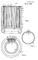
- FIG. 1 shows a longitudinal section through a dome contact piece designed according to the invention.
- FIG. 2 shows, partially in section, a view of an end face of the dome contact piece, viewed in the direction of the arrow drawn in FIG. 1.
- Figure 3 shows the inner cylindrical housing on a smaller scale.
- the dome contact piece 1 for the connection of two round conductors of a compressed gas-insulated metal encapsulated high-voltage switchgear has a thick-walled outer housing 2, which has a substantially cylindrical shape.
- the front outer edges 3 as well as the edges 4 next to a constriction 5 for receiving a safety spring, not shown, are greatly rounded, so that the outer housing 2 also acts as a shield controlling the electrical field in the course of the conductor connection.
- the inner diameter 6 in the area of the constriction 5 is smaller than the inner diameter 7 for receiving the lamellae 8, so that a paragraph 9 forms between the two, on which the lamellae 8 abut one side.
- Each lamella 8 is trapezoidal.
- the pointed side 10 of the lamella 8 forms the contact surface with the conductors (not shown) to be connected.
- the blunt side facing the outer housing 2 contains a central groove 11, which is laterally spaced 12 from the slat side surface 13.
- a leaf spring 14 is arranged, which supports the lamella 8 with respect to the outer housing 2 and thus causes the contact pressure of the lamella 8.
- the leaf spring 14 does not abut the inner bore 15 of the outer housing 2, but a thin-walled cylindrical housing 16 is inserted into this.
- This thin-walled cylindrical housing 16 is formed from a strip of thin-walled bronze sheet bent into a cylinder.
- the width of the sheet approximately corresponds to the length of the lamellae 8.
- One of the axially extending edges 17 of the sheet is bent radially inward at a height 19 selected less than the lamella height 18.
- this bent edge 17 forms an intermediate wall 20 which projects between two lamellae 8.
- the other, not bent, axially extending edge 21 of the thin-walled cylindrical housing 16 forms a narrow gap 22 to the bent edge 17, which is smaller than the distance 12 between the lamella side surface 13 and the groove 11 for receiving the leaf spring 14
- Leaf springs 14 each on the inner surface of the thin-walled cylindrical housing 16, so that the same contact pressure is ensured along the entire circumference of the dome contact piece 1.
- the thin-walled housing 16 absorbs the contact force itself, but transmits it directly to the outer housing 2.
- the assembly of the dome contact piece 1 is very simple. First, the thin-walled cylindrical housing 16 is inserted into the inner bore 15 of the outer housing 2 until it comes to rest on the paragraph 9. Then the individual slats 8 are inserted from the side and also reach paragraph 9 to the system. Now the leaf springs 14 are inserted into each groove 11 of the slats 8. Finally, in front of the end face of the thin-walled cylindrical housing 16, the leaf springs 14 and the lamellae 8, a disk 23 is placed for axial securing, which is fixed at some points in the outer housing 2 by caulking.
- the intermediate wall 20 of the cylindrical housing 16 projecting between two lamellae 8 provides precise lateral guidance and fixing of the lamellae 8, so that they are prevented from tilting in a simple manner, which leads to a reduction in the current carrying capacity would lead.
Landscapes
- Coupling Device And Connection With Printed Circuit (AREA)
- Arc-Extinguishing Devices That Are Switches (AREA)
- Springs (AREA)
Applications Claiming Priority (2)
| Application Number | Priority Date | Filing Date | Title |
|---|---|---|---|
| DE8431557U DE8431557U1 (de) | 1984-10-25 | 1984-10-25 | Kuppelkontaktstück zum Verbinden runder elektrischer Leiter |
| DE8431557U | 1984-10-25 |
Publications (3)
| Publication Number | Publication Date |
|---|---|
| EP0182736A2 true EP0182736A2 (fr) | 1986-05-28 |
| EP0182736A3 EP0182736A3 (en) | 1986-06-04 |
| EP0182736B1 EP0182736B1 (fr) | 1988-06-15 |
Family
ID=6772126
Family Applications (1)
| Application Number | Title | Priority Date | Filing Date |
|---|---|---|---|
| EP85730142A Expired EP0182736B1 (fr) | 1984-10-25 | 1985-10-16 | Pièce de connexion pour raccorder des conducteurs électriques ronds |
Country Status (3)
| Country | Link |
|---|---|
| EP (1) | EP0182736B1 (fr) |
| JP (1) | JPS61104569A (fr) |
| DE (2) | DE8431557U1 (fr) |
Cited By (2)
| Publication number | Priority date | Publication date | Assignee | Title |
|---|---|---|---|---|
| EP0789424A3 (fr) * | 1996-02-08 | 1998-11-11 | Asea Brown Boveri Ag | Elément de raccord pour deux sections de conducteur à haute tension |
| EP3748780A1 (fr) * | 2019-06-05 | 2020-12-09 | Tyco Electronics UK Ltd | Borne de contact |
Families Citing this family (1)
| Publication number | Priority date | Publication date | Assignee | Title |
|---|---|---|---|---|
| JP5714516B2 (ja) * | 2012-01-23 | 2015-05-07 | サンコール株式会社 | 電気コネクタ |
Family Cites Families (4)
| Publication number | Priority date | Publication date | Assignee | Title |
|---|---|---|---|---|
| DE1160914B (de) * | 1961-11-24 | 1964-01-09 | Siemens Ag | Kuppelkontaktstueck |
| GB1070033A (en) * | 1964-06-24 | 1967-05-24 | Pyle National Co | Improvements in or relating to electrical contacts |
| CH474876A (de) * | 1968-11-05 | 1969-06-30 | Bbc Brown Boveri & Cie | Elektrische Kontaktanordnung |
| US3713075A (en) * | 1971-04-26 | 1973-01-23 | Ite Imperial Corp | Dielectric shield for plug-in contacts |
-
1984
- 1984-10-25 DE DE8431557U patent/DE8431557U1/de not_active Expired
-
1985
- 1985-10-16 DE DE8585730142T patent/DE3563402D1/de not_active Expired
- 1985-10-16 EP EP85730142A patent/EP0182736B1/fr not_active Expired
- 1985-10-22 JP JP60236253A patent/JPS61104569A/ja active Granted
Cited By (2)
| Publication number | Priority date | Publication date | Assignee | Title |
|---|---|---|---|---|
| EP0789424A3 (fr) * | 1996-02-08 | 1998-11-11 | Asea Brown Boveri Ag | Elément de raccord pour deux sections de conducteur à haute tension |
| EP3748780A1 (fr) * | 2019-06-05 | 2020-12-09 | Tyco Electronics UK Ltd | Borne de contact |
Also Published As
| Publication number | Publication date |
|---|---|
| DE3563402D1 (en) | 1988-07-21 |
| EP0182736A3 (en) | 1986-06-04 |
| JPH0313709B2 (fr) | 1991-02-25 |
| JPS61104569A (ja) | 1986-05-22 |
| DE8431557U1 (de) | 1985-03-21 |
| EP0182736B1 (fr) | 1988-06-15 |
Similar Documents
| Publication | Publication Date | Title |
|---|---|---|
| DE2651108C3 (de) | Elektrische Kontaktvorrichtung | |
| DE2615996C2 (de) | Einstückig aus Metallblech gestanzte und geformte elektrische Anschlußklemme | |
| DE3722069C2 (fr) | ||
| DE2338056B2 (de) | Elektrische Anschlußklemme | |
| DE9311781U1 (de) | Kabelstecker für vieladrige Kabel | |
| DE2449042A1 (de) | Elektrischer verbinder | |
| DE69603318T2 (de) | Vorrichtung für elektrische Kontakte mit Isolationsverschiebung | |
| DD269496A5 (de) | Schneidklemm-huelsenkontakt | |
| DE69523729T2 (de) | Schneidklemmverbinder | |
| EP0182736B1 (fr) | Pièce de connexion pour raccorder des conducteurs électriques ronds | |
| DE69319259T2 (de) | Verbesserte Kontakte für den Anschluss von Spulenwicklungen | |
| DE29705134U1 (de) | Steckerbuchse | |
| DE4320539C2 (de) | Leitungsdraht-Verbindungsklemme | |
| DE3625864A1 (de) | Elektrische kontaktvorrichtung | |
| DE2438234C3 (de) | Elektrodenbaugruppe für Mehrstrahlerzeugersysteme und Verfahren zum Betrieb dieser Baugruppe | |
| DE2936616C2 (de) | Verbinder für zwei Koaxialkabelenden | |
| EP3869621B1 (fr) | Borne de raccordement | |
| DE69103372T2 (de) | Spulenkörper mit winkelrechten Anschlussstiften. | |
| EP0210126B1 (fr) | Pièce de contact d'accouplement pour un enfichage entre deux conducteurs cylindriques d'une installation de commutation haute tension à isolation sous pression gazeuse en enceinte fermée | |
| DE2304639B2 (de) | Fassungsanordnung für elektrische Steckerkupplungen | |
| DE19539958B4 (de) | Kontakt | |
| DE4225544C1 (de) | Kabelsteckverbinder für Flachbandkabel | |
| DE9304392U1 (de) | Kontaktelement mit Schneidklemm- und Crimpanschluß | |
| DE1160914B (de) | Kuppelkontaktstueck | |
| EP1109272B1 (fr) | Porte-balai pour balai en charbon |
Legal Events
| Date | Code | Title | Description |
|---|---|---|---|
| PUAI | Public reference made under article 153(3) epc to a published international application that has entered the european phase |
Free format text: ORIGINAL CODE: 0009012 |
|
| PUAL | Search report despatched |
Free format text: ORIGINAL CODE: 0009013 |
|
| AK | Designated contracting states |
Kind code of ref document: A2 Designated state(s): CH DE FR GB LI NL SE |
|
| AK | Designated contracting states |
Kind code of ref document: A3 Designated state(s): CH DE FR GB LI NL SE |
|
| 17P | Request for examination filed |
Effective date: 19860626 |
|
| 17Q | First examination report despatched |
Effective date: 19870929 |
|
| GRAA | (expected) grant |
Free format text: ORIGINAL CODE: 0009210 |
|
| AK | Designated contracting states |
Kind code of ref document: B1 Designated state(s): CH DE FR GB LI NL SE |
|
| REF | Corresponds to: |
Ref document number: 3563402 Country of ref document: DE Date of ref document: 19880721 |
|
| ET | Fr: translation filed | ||
| GBT | Gb: translation of ep patent filed (gb section 77(6)(a)/1977) | ||
| PLBE | No opposition filed within time limit |
Free format text: ORIGINAL CODE: 0009261 |
|
| STAA | Information on the status of an ep patent application or granted ep patent |
Free format text: STATUS: NO OPPOSITION FILED WITHIN TIME LIMIT |
|
| 26N | No opposition filed | ||
| EAL | Se: european patent in force in sweden |
Ref document number: 85730142.8 |
|
| PGFP | Annual fee paid to national office [announced via postgrant information from national office to epo] |
Ref country code: GB Payment date: 19980909 Year of fee payment: 14 |
|
| PGFP | Annual fee paid to national office [announced via postgrant information from national office to epo] |
Ref country code: SE Payment date: 19981027 Year of fee payment: 14 |
|
| PGFP | Annual fee paid to national office [announced via postgrant information from national office to epo] |
Ref country code: NL Payment date: 19981030 Year of fee payment: 14 |
|
| PG25 | Lapsed in a contracting state [announced via postgrant information from national office to epo] |
Ref country code: GB Free format text: LAPSE BECAUSE OF NON-PAYMENT OF DUE FEES Effective date: 19991016 |
|
| PG25 | Lapsed in a contracting state [announced via postgrant information from national office to epo] |
Ref country code: SE Free format text: THE PATENT HAS BEEN ANNULLED BY A DECISION OF A NATIONAL AUTHORITY Effective date: 19991030 |
|
| PG25 | Lapsed in a contracting state [announced via postgrant information from national office to epo] |
Ref country code: NL Free format text: LAPSE BECAUSE OF NON-PAYMENT OF DUE FEES Effective date: 20000501 |
|
| GBPC | Gb: european patent ceased through non-payment of renewal fee |
Effective date: 19991016 |
|
| EUG | Se: european patent has lapsed |
Ref document number: 85730142.8 |
|
| NLV4 | Nl: lapsed or anulled due to non-payment of the annual fee |
Effective date: 20000501 |
|
| PGFP | Annual fee paid to national office [announced via postgrant information from national office to epo] |
Ref country code: FR Payment date: 20031029 Year of fee payment: 19 |
|
| PGFP | Annual fee paid to national office [announced via postgrant information from national office to epo] |
Ref country code: DE Payment date: 20031217 Year of fee payment: 19 |
|
| PGFP | Annual fee paid to national office [announced via postgrant information from national office to epo] |
Ref country code: CH Payment date: 20040114 Year of fee payment: 19 |
|
| PG25 | Lapsed in a contracting state [announced via postgrant information from national office to epo] |
Ref country code: LI Free format text: LAPSE BECAUSE OF NON-PAYMENT OF DUE FEES Effective date: 20041031 Ref country code: CH Free format text: LAPSE BECAUSE OF NON-PAYMENT OF DUE FEES Effective date: 20041031 |
|
| PG25 | Lapsed in a contracting state [announced via postgrant information from national office to epo] |
Ref country code: DE Free format text: LAPSE BECAUSE OF NON-PAYMENT OF DUE FEES Effective date: 20050503 |
|
| REG | Reference to a national code |
Ref country code: CH Ref legal event code: PL |
|
| PG25 | Lapsed in a contracting state [announced via postgrant information from national office to epo] |
Ref country code: FR Free format text: LAPSE BECAUSE OF NON-PAYMENT OF DUE FEES Effective date: 20050630 |
|
| REG | Reference to a national code |
Ref country code: FR Ref legal event code: ST |