EP0182749A2 - Zerkleinerer mit zwei horizontal rotierenden versetzten Achsen - Google Patents
Zerkleinerer mit zwei horizontal rotierenden versetzten Achsen Download PDFInfo
- Publication number
- EP0182749A2 EP0182749A2 EP85810548A EP85810548A EP0182749A2 EP 0182749 A2 EP0182749 A2 EP 0182749A2 EP 85810548 A EP85810548 A EP 85810548A EP 85810548 A EP85810548 A EP 85810548A EP 0182749 A2 EP0182749 A2 EP 0182749A2
- Authority
- EP
- European Patent Office
- Prior art keywords
- flap
- sliding
- chamber
- shaft
- shredder
- Prior art date
- Legal status (The legal status is an assumption and is not a legal conclusion. Google has not performed a legal analysis and makes no representation as to the accuracy of the status listed.)
- Granted
Links
Images


Classifications
-
- B—PERFORMING OPERATIONS; TRANSPORTING
- B02—CRUSHING, PULVERISING, OR DISINTEGRATING; PREPARATORY TREATMENT OF GRAIN FOR MILLING
- B02C—CRUSHING, PULVERISING, OR DISINTEGRATING IN GENERAL; MILLING GRAIN
- B02C18/00—Disintegrating by knives or other cutting or tearing members which chop material into fragments
- B02C18/0084—Disintegrating by knives or other cutting or tearing members which chop material into fragments specially adapted for disintegrating garbage, waste or sewage
-
- B—PERFORMING OPERATIONS; TRANSPORTING
- B02—CRUSHING, PULVERISING, OR DISINTEGRATING; PREPARATORY TREATMENT OF GRAIN FOR MILLING
- B02C—CRUSHING, PULVERISING, OR DISINTEGRATING IN GENERAL; MILLING GRAIN
- B02C18/00—Disintegrating by knives or other cutting or tearing members which chop material into fragments
- B02C18/06—Disintegrating by knives or other cutting or tearing members which chop material into fragments with rotating knives
- B02C18/14—Disintegrating by knives or other cutting or tearing members which chop material into fragments with rotating knives within horizontal containers
- B02C18/142—Disintegrating by knives or other cutting or tearing members which chop material into fragments with rotating knives within horizontal containers with two or more inter-engaging rotatable cutter assemblies
Definitions
- the present invention relates to a shredder comprising two substantially horizontal and parallel rotary shafts, offset vertically and horizontally with respect to each other, equipped with shredding protruding members and arranged in a chamber in which the materials to be shredded are introduced by above and are guided so as to pass between the two rotary shafts, said chamber comprising a wall for guiding the materials to be shredded which is closer to the lower shaft than to the upper shaft and which has an opening closed by at least a movable flap which extends substantially over the entire length of the wall.
- shredding To eliminate solid waste, in particular by incineration, it is often necessary to reduce its dimensions by shredding it, in order to obtain fragments of an appropriate particle size.
- apparatuses called “shredders” are used, in which the materials to be treated pass between two parallel shafts provided with shredding members such as teeth or hammers, and rotating in opposite directions and at different speeds, so as to crush and lacerate the waste.
- the two rotary shafts are arranged horizontally in a chamber in the form of a vertical duct, the materials being introduced from above onto the two shafts and discharging downwards once shredded.
- the feeding and evacuation are done automatically by gravity, which ensures simple and safe operation.
- the materials to be shredded may contain specially hard parts which cannot be crushed or pass between the trees and which is difficult to evacuate from the chamber.
- the present invention aims to remedy the aforementioned drawbacks by improving the known shredders so as to provide a robust and safe device, allowing automatic evacuation of particularly hard elements.
- the invention relates to a shredder of the type mentioned above, characterized in that the guide wall comprises a sliding shutter, disposed opposite the lower shaft and sliding along a path in an arc of a circle which is concentric with this shaft, this component comprising shutter baffles between which pass the shredding members mounted on the lower shaft.
- the shredder comprises a hydraulic mechanism for opening and closing the sliding shutter, said mechanism being arranged outside the chamber.
- 11 further comprises a mechanism for locking the sliding shutter in the closed position, this mechanism preferably being provided with a hydraulic control.
- the sliding shutter may comprise, along its upper edge, a deflector arranged outside the chamber and arranged to guide the materials which escape therefrom out of this chamber.
- the guide wall may include an upper shutter pivoting about a horizontal axis located near the upper edge of this shutter, the lower edge of the shutter being, in the closed position, pressing against the upper edge of the sliding shutter.
- the upper flap preferably comprises, along its lower edge, a support plate arranged to be applied against the deflector of the lower flap in the closed position of the two flaps.
- the shredder may also include a hydraulic mechanism for opening and closing the upper flap.
- the shredder shown in FIG. 1 essentially comprises a body 1 of substantially parallelepiped shape, the interior of which comprises a chamber 2 which is open upwards and downwards.
- a hopper 3 is fixed to the body 1 above the upper opening of the chamber 2 to introduce the materials to be treated into the chamber by gravity.
- the body 1 is mounted on an openwork frame 4, which allows the shredded products to fall freely through the lower orifice of the chamber 2, for example towards a pit, a wagon or a conveyor in order to their evacuation.
- the shredder comprises two rotary shafts 5 and 6 with horizontal and parallel axes, equipped with projecting shredding members and driven respectively by hydraulic motors 7 and 8 which are mounted on the external front faces of the body 1. These motors are supplied with high pressure hydraulic fluid via an automatic control device (not shown).
- the respective axes 5a and 6a of the two rotary shafts 5 and 6 are offset both vertically and horizontally relative to one another.
- the upper shaft 5 extends in the upper part of the chamber 2, while the lower shaft 6 is arranged below the shaft 5, in a position such that its axis 6a is substantially in a vertical plane 10 which is tangent to the peripheral surface of the upper shaft 5.
- each of the two shafts 5 and 6 comprises, in a known manner, a series of cutting rings 11 which are provided with teeth on their periphery and which are separated from each other along each shaft by rings 12 which cooperate with the teeth of the cutting rings of the other shaft to cut the materials to be treated.
- the two shafts 5 and 6 are rotated by their respective motors in opposite directions and at slightly different speeds, so that the materials are driven by the teeth of the cutting rings 11 so as to pass between the two shafts 5 and 6 and to be sheared on the one hand by the adjacent cutting rings and, on the other hand, between each cutting ring 11 and the ring 12 which faces it.
- Chamber 2 has a rear wall 14 which, in the example shown here, is substantially vertical and which is equipped with a row of shutter baffles 15, distributed between the cutting rings 11 of the upper shaft 5 to prevent an untimely rise of shredded materials.
- the chamber 2 On the other side of the two shafts, the chamber 2 has, over its entire length, a guide wall 16 which is inclined so as to form, in front of the two shafts, a space which narrows downwards to bring the materials towards the area where they will be gripped by the teeth of the cutting rings 11 of the two shafts.
- a guide wall 16 which is inclined so as to form, in front of the two shafts, a space which narrows downwards to bring the materials towards the area where they will be gripped by the teeth of the cutting rings 11 of the two shafts.
- it is simply a substantially planar wall which is closer to the lower shaft 6 than to the upper shaft 5.
- the guide wall 16 consists essentially of two movable flaps, namely a lower flap 20 which is arranged opposite the lower shaft 6 and an upper flap 21 which is adjacent to the lower flap 20 and bears against him.
- the flaps 20 and 21 are drawn here in solid lines in their closed position, in which they form a continuous wall from the top of the chamber 2 to below the lower shaft 6.
- the lower flap 20 is provided with shutter baffles 22 which are similar to baffles 15 of the rear wall 14.
- the lower flap 20 essentially comprises a thick front plate 24 made of sheet metal stiffened by side members 25, and a deflector 26 constituted by a sheet welded along the upper edge of the front plate 24.
- these plates are fixed on a composite cross-member 27 which is parallel to the front wall of the body 1.
- each cross-member 27 carries two pins 28 and 29 which are engaged in a slide 30 in the form of an arc of a circle formed on along the front wall of the body 1. This circular arc is centered on the axis 6a of the lower shaft.
- the lower flap 20 can be moved by sliding around the lower shaft 6 to its open position drawn in broken lines and indicated by 20a. In this position, the deflector 26 occupies a position 26a in which it is inclined towards the outside of the chamber 2, above a slide 32.
- the lower flap 20 is locked in position by means of a locking mechanism which will be described later and which engages in an orifice 33 formed in each of the crosspieces 27.
- cover plates 34 and 35 which close off the parts of the slides 30 which are exposed, respectively in the closed position and the open position of the flap in order to prevent products enter it.
- the upper flap 21 is constituted by an upper shaft 40, an anterior thick plate 41 supported by stiffeners 42 and a support plate 43 welded along the lower edge of the front plate 41.
- the upper shaft 40 is pivotally mounted in the front walls of the body 1 of the shredder.
- the upper flap 21 When the lower flap 20 is in the closed position, the upper flap 21 is kept in the closed position because its support plate 43 is applied against the deflector 26 by the weight of the flap and of the materials located in the chamber 2.
- the lower flap 20 when the lower flap 20 is open, it is also possible to open the upper flap 21 by pivoting it on its shaft 40 to bring it into its open position drawn in broken lines and designated by 21a.
- Fig. 3 shows a front face of the body 1 of the shredder, comprising respective mounts 45 and 46 for the shafts 5 and 6. These mounts are known per se and they will not be described here in detail.
- the mount 46 of the lower shaft is integral with the hydraulic motor driving this shaft; it includes a return arm 47 fixed in an elastic support 48.
- fig. 3 shows the mechanisms for actuating the flaps 20 and 21.
- the pins 28 and 29, integral with the lower flap 20 and engaged in the slide 30, are fixed to a stirrup 50, on which the piston rod of a jack is articulated hydraulic 51, the other end of which is mounted on the body 1.
- the jack 51 makes it possible to move the stirrup 50 along the slide 30 to its lower position 50a drawn in broken lines corresponding to the open position of the flap lower 20, then bring it back to its original position.
- a similar device is provided on the other front face of the body 1.
- the upper shaft 40 of the upper flap 21 is mounted in a pivot in each of the front faces of the body 1 and it is secured, outside this body, of a lever 53 on which the piston rod of a hydraulic cylinder 54 which makes it possible to pivot the upper flap in one direction and in the other.
- An identical cylinder can be provided at the other end of the shredder.
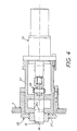
- fig. 3 shows the end of a hydraulic cylinder 55 for controlling the locking mechanism of the lower flap. This mechanism is shown in more detail in FIG. 4.
- said locking mechanism comprises a lock 56 sliding in a support 57, this lock being coupled by a hinge 58 to the piston rod of the control jack 55.
- the end of the lock 56 is slightly bevelled and it engages in the corresponding orifice 33 formed in the end crosspiece 27 of the lower flap 20 or, more precisely, in a block integral with the crosspiece 27.
- the latch 56 occupies the position 56a drawn in broken lines.
- the support 57 of this mechanism is fixed to the front wall of the body 1 of the shredder in a position corresponding to the position of the orifice 33 when the lower flap 20 occupies its closed position.
- the latch 56 is advanced in the orifice 33 until the latch is locked in position by the bevelled faces of the latch 56. The latter then supports most of the transverse forces exerted on the lower flap 20 and partly on the upper flap 21 during the operation of the shredder.
- a plane 60 common to the two axes 5a and 6a is inclined, with respect to the horizontal, by an angle e equal to approximately 71 °.
- e the angle e
- the inclination 6 can be between 30 ° and 80 °; but preferably between 60 ° and 75 °.
- the slide 30 could be eliminated in certain embodiments or replaced by any other equivalent guide means, for example by two arms which pivot around the axis of the lower shaft.
- the guide wall could comprise two adjacent sliding flaps arranged one above the other, the lower sliding flap being arranged opposite from the lower shaft.
Landscapes
- Engineering & Computer Science (AREA)
- Food Science & Technology (AREA)
- Environmental & Geological Engineering (AREA)
- Crushing And Pulverization Processes (AREA)
- Disintegrating Or Milling (AREA)
- Crushing And Grinding (AREA)
Priority Applications (1)
| Application Number | Priority Date | Filing Date | Title |
|---|---|---|---|
| AT85810548T ATE54263T1 (de) | 1984-11-16 | 1985-11-18 | Zerkleinerer mit zwei horizontal rotierenden versetzten achsen. |
Applications Claiming Priority (2)
| Application Number | Priority Date | Filing Date | Title |
|---|---|---|---|
| FR8417637 | 1984-11-16 | ||
| FR8417637A FR2573327B1 (fr) | 1984-11-16 | 1984-11-16 | Dechiqueteur comportant deux arbres rotatifs a axes horizontaux |
Publications (3)
| Publication Number | Publication Date |
|---|---|
| EP0182749A2 true EP0182749A2 (de) | 1986-05-28 |
| EP0182749A3 EP0182749A3 (en) | 1988-04-13 |
| EP0182749B1 EP0182749B1 (de) | 1990-07-04 |
Family
ID=9309745
Family Applications (1)
| Application Number | Title | Priority Date | Filing Date |
|---|---|---|---|
| EP85810548A Expired - Lifetime EP0182749B1 (de) | 1984-11-16 | 1985-11-18 | Zerkleinerer mit zwei horizontal rotierenden versetzten Achsen |
Country Status (4)
| Country | Link |
|---|---|
| EP (1) | EP0182749B1 (de) |
| AT (1) | ATE54263T1 (de) |
| DE (1) | DE3578559D1 (de) |
| FR (1) | FR2573327B1 (de) |
Cited By (5)
| Publication number | Priority date | Publication date | Assignee | Title |
|---|---|---|---|---|
| US5332164A (en) * | 1990-12-31 | 1994-07-26 | Rexworks, Inc. | Materials grinder |
| WO1995013139A1 (en) * | 1993-11-12 | 1995-05-18 | Environmental Products Corporation | Container cutting assembly |
| EP0687503A1 (de) * | 1994-06-16 | 1995-12-20 | Werner Doppstadt | Walzenzerkleinerer |
| WO1998007519A1 (fr) * | 1996-08-21 | 1998-02-26 | Compagnie Française Des Ferrailles | Installation de pre-broyage |
| US5921372A (en) * | 1997-05-02 | 1999-07-13 | Environmental Products Corporation | Multiple chambered container compaction assembly with diverter |
Families Citing this family (2)
| Publication number | Priority date | Publication date | Assignee | Title |
|---|---|---|---|---|
| DE3723928A1 (de) * | 1987-05-16 | 1988-11-24 | Poettinger Alois Landmasch | Schneidwalzenzerkleinerer |
| DE19514951C2 (de) * | 1995-04-24 | 1998-02-19 | Willibald Gmbh Maschinenfabrik | Mobiler Abfall-Zerkleinerer |
Family Cites Families (4)
| Publication number | Priority date | Publication date | Assignee | Title |
|---|---|---|---|---|
| FR2220307A1 (en) * | 1973-03-05 | 1974-10-04 | Locaner Sa | Rubbish shredder with horizontal parallel rollers - guides direct charge downwards around stepped surface rollers |
| GB1439103A (en) * | 1974-01-19 | 1976-06-09 | Anda Ltd | Waste disposal apparatus |
| GB2024654A (en) * | 1978-07-05 | 1980-01-16 | Metal Box Co Ltd | Dealing with intractable material in a shredding machine |
| DE2838001A1 (de) * | 1978-08-31 | 1980-04-24 | Peter Voelskow | Zerkleinerungsmaschine fuer sperrige abfaelle |
-
1984
- 1984-11-16 FR FR8417637A patent/FR2573327B1/fr not_active Expired
-
1985
- 1985-11-18 DE DE8585810548T patent/DE3578559D1/de not_active Expired - Fee Related
- 1985-11-18 AT AT85810548T patent/ATE54263T1/de not_active IP Right Cessation
- 1985-11-18 EP EP85810548A patent/EP0182749B1/de not_active Expired - Lifetime
Cited By (7)
| Publication number | Priority date | Publication date | Assignee | Title |
|---|---|---|---|---|
| US5332164A (en) * | 1990-12-31 | 1994-07-26 | Rexworks, Inc. | Materials grinder |
| WO1995013139A1 (en) * | 1993-11-12 | 1995-05-18 | Environmental Products Corporation | Container cutting assembly |
| US5560552A (en) * | 1993-11-12 | 1996-10-01 | Environmental Products Corporation | Container cutting assembly |
| EP0687503A1 (de) * | 1994-06-16 | 1995-12-20 | Werner Doppstadt | Walzenzerkleinerer |
| WO1998007519A1 (fr) * | 1996-08-21 | 1998-02-26 | Compagnie Française Des Ferrailles | Installation de pre-broyage |
| FR2752535A1 (fr) * | 1996-08-21 | 1998-02-27 | Ferrailles Cie Fse | Installation de pre-broyage |
| US5921372A (en) * | 1997-05-02 | 1999-07-13 | Environmental Products Corporation | Multiple chambered container compaction assembly with diverter |
Also Published As
| Publication number | Publication date |
|---|---|
| DE3578559D1 (de) | 1990-08-09 |
| EP0182749B1 (de) | 1990-07-04 |
| FR2573327A1 (fr) | 1986-05-23 |
| FR2573327B1 (fr) | 1988-05-06 |
| EP0182749A3 (en) | 1988-04-13 |
| ATE54263T1 (de) | 1990-07-15 |
Similar Documents
| Publication | Publication Date | Title |
|---|---|---|
| BE1004322A3 (fr) | Dispositif de manutention d'une goulotte de distribution d'un four a cuve et mecanisme d'entrainement adapte a ce dispositif. | |
| EP0182749B1 (de) | Zerkleinerer mit zwei horizontal rotierenden versetzten Achsen | |
| FR2906964A1 (fr) | Unite de tondeuse pourvue d'une cloison avec un passage d'air. | |
| FR2846512A1 (fr) | Appareil collecteur d'herbe et tondeuse le comportant | |
| EP2925451B1 (de) | Rüttelsieb für einen prallbrecher, prallbrecher mit diesem rüttelsieb und zerkleinerungsanlage | |
| FR2862480A1 (fr) | Systeme collecteur d'herbe ayant un conduit | |
| EP0620043A2 (de) | Zerkleinerungsapparat für feste Gegenstände | |
| FR2491952A1 (fr) | Perfectionnements aux installations d'alimentation des fours a cuve a gueulard sans cloche | |
| WO2012020199A1 (fr) | Concasseur ou broyeur a marteaux, dechiqueteur ou analogue pourvu d'un dispositif d'alimentation mobile | |
| EP0076527A1 (de) | Vorrichtung zum Sammeln und Zusammendrücken von Müll | |
| EP2072138A1 (de) | Materialzerkleinerungsmaschine mit Umlaufrotoren | |
| FR2527477A1 (fr) | Broyeur a marteaux a dispositif d'ejection perfectionne | |
| EP0081447B1 (de) | Maschinen zur Entnahme von Futterblocks aus einem Silo | |
| EP0392890B1 (de) | Silofutterschneider und Schneidvorrichtung für Futter, insbesondere Silofutter | |
| EP0014135B1 (de) | Vorrichtungen zum in Scheiben schneiden von Lachs | |
| FR3043996A1 (fr) | Bouclier de poussee, dispositif de poussee comprenant un tel bouclier, benne poussoir equipee d'un tel dispositif de poussee, et vehicule porteur correspondant | |
| FR2899067A1 (fr) | Casseuse a noix | |
| EP0338653B1 (de) | Ladegerät mit einer seitlich schneidenden Vorrichtung für Siloentnahme- und Verteilergeräte | |
| EP0543688B1 (de) | Silofutterschneider | |
| EP1657229B1 (de) | Vorrichtung zur kompostierung von grünabfällen | |
| FR2748630A1 (fr) | Appareil destine a creer un lit regulier a partir d'une matiere conditionnee en balle ou botte | |
| FR3066127B1 (fr) | Broyeur pour vegetaux | |
| FR2505218A1 (fr) | Dispositif de suspension et de commande pour une poche de coulee | |
| FR2538746A1 (fr) | Dispositif permettant de supporter la partie a decouper d'une tole et de l'evacuer apres son decoupage | |
| FR2642098A1 (fr) | Perfectionnement aux godets ouvrants de machines de travaux publics |
Legal Events
| Date | Code | Title | Description |
|---|---|---|---|
| PUAI | Public reference made under article 153(3) epc to a published international application that has entered the european phase |
Free format text: ORIGINAL CODE: 0009012 |
|
| AK | Designated contracting states |
Kind code of ref document: A2 Designated state(s): AT BE CH DE FR GB IT LI LU NL SE |
|
| PUAL | Search report despatched |
Free format text: ORIGINAL CODE: 0009013 |
|
| AK | Designated contracting states |
Kind code of ref document: A3 Designated state(s): AT BE CH DE FR GB IT LI LU NL SE |
|
| 17P | Request for examination filed |
Effective date: 19880930 |
|
| 17Q | First examination report despatched |
Effective date: 19890907 |
|
| GRAA | (expected) grant |
Free format text: ORIGINAL CODE: 0009210 |
|
| AK | Designated contracting states |
Kind code of ref document: B1 Designated state(s): AT BE CH DE FR GB IT LI LU NL SE |
|
| REF | Corresponds to: |
Ref document number: 54263 Country of ref document: AT Date of ref document: 19900715 Kind code of ref document: T |
|
| ITF | It: translation for a ep patent filed | ||
| REF | Corresponds to: |
Ref document number: 3578559 Country of ref document: DE Date of ref document: 19900809 |
|
| GBT | Gb: translation of ep patent filed (gb section 77(6)(a)/1977) | ||
| PLBE | No opposition filed within time limit |
Free format text: ORIGINAL CODE: 0009261 |
|
| STAA | Information on the status of an ep patent application or granted ep patent |
Free format text: STATUS: NO OPPOSITION FILED WITHIN TIME LIMIT |
|
| 26N | No opposition filed | ||
| ITTA | It: last paid annual fee | ||
| EPTA | Lu: last paid annual fee | ||
| EAL | Se: european patent in force in sweden |
Ref document number: 85810548.9 |
|
| REG | Reference to a national code |
Ref country code: GB Ref legal event code: IF02 |
|
| PGFP | Annual fee paid to national office [announced via postgrant information from national office to epo] |
Ref country code: BE Payment date: 20031024 Year of fee payment: 19 |
|
| PGFP | Annual fee paid to national office [announced via postgrant information from national office to epo] |
Ref country code: LU Payment date: 20031031 Year of fee payment: 19 |
|
| PGFP | Annual fee paid to national office [announced via postgrant information from national office to epo] |
Ref country code: DE Payment date: 20031105 Year of fee payment: 19 |
|
| PGFP | Annual fee paid to national office [announced via postgrant information from national office to epo] |
Ref country code: SE Payment date: 20031110 Year of fee payment: 19 |
|
| PGFP | Annual fee paid to national office [announced via postgrant information from national office to epo] |
Ref country code: GB Payment date: 20031119 Year of fee payment: 19 |
|
| PGFP | Annual fee paid to national office [announced via postgrant information from national office to epo] |
Ref country code: NL Payment date: 20031126 Year of fee payment: 19 |
|
| PGFP | Annual fee paid to national office [announced via postgrant information from national office to epo] |
Ref country code: AT Payment date: 20031128 Year of fee payment: 19 |
|
| PGFP | Annual fee paid to national office [announced via postgrant information from national office to epo] |
Ref country code: CH Payment date: 20040209 Year of fee payment: 19 |
|
| PG25 | Lapsed in a contracting state [announced via postgrant information from national office to epo] |
Ref country code: LU Free format text: LAPSE BECAUSE OF NON-PAYMENT OF DUE FEES Effective date: 20041118 Ref country code: GB Free format text: LAPSE BECAUSE OF NON-PAYMENT OF DUE FEES Effective date: 20041118 Ref country code: AT Free format text: LAPSE BECAUSE OF NON-PAYMENT OF DUE FEES Effective date: 20041118 |
|
| PG25 | Lapsed in a contracting state [announced via postgrant information from national office to epo] |
Ref country code: SE Free format text: LAPSE BECAUSE OF NON-PAYMENT OF DUE FEES Effective date: 20041119 |
|
| PGFP | Annual fee paid to national office [announced via postgrant information from national office to epo] |
Ref country code: FR Payment date: 20041122 Year of fee payment: 20 |
|
| PG25 | Lapsed in a contracting state [announced via postgrant information from national office to epo] |
Ref country code: LI Free format text: LAPSE BECAUSE OF NON-PAYMENT OF DUE FEES Effective date: 20041130 Ref country code: CH Free format text: LAPSE BECAUSE OF NON-PAYMENT OF DUE FEES Effective date: 20041130 Ref country code: BE Free format text: LAPSE BECAUSE OF NON-PAYMENT OF DUE FEES Effective date: 20041130 |
|
| BERE | Be: lapsed |
Owner name: *SOC. INDUSTRIELLE DE LA DOUX S.A. Effective date: 20041130 |
|
| PG25 | Lapsed in a contracting state [announced via postgrant information from national office to epo] |
Ref country code: NL Free format text: LAPSE BECAUSE OF NON-PAYMENT OF DUE FEES Effective date: 20050601 Ref country code: DE Free format text: LAPSE BECAUSE OF NON-PAYMENT OF DUE FEES Effective date: 20050601 |
|
| EUG | Se: european patent has lapsed | ||
| GBPC | Gb: european patent ceased through non-payment of renewal fee |
Effective date: 20041118 |
|
| REG | Reference to a national code |
Ref country code: CH Ref legal event code: PL |
|
| NLV4 | Nl: lapsed or anulled due to non-payment of the annual fee |
Effective date: 20050601 |
|
| BERE | Be: lapsed |
Owner name: *SOC. INDUSTRIELLE DE LA DOUX S.A. Effective date: 20041130 |