EP0182918B1 - Numerisch gesteuerte vorrichtung mit programmierbarer spiegelbildfunktion - Google Patents
Numerisch gesteuerte vorrichtung mit programmierbarer spiegelbildfunktion Download PDFInfo
- Publication number
- EP0182918B1 EP0182918B1 EP85902638A EP85902638A EP0182918B1 EP 0182918 B1 EP0182918 B1 EP 0182918B1 EP 85902638 A EP85902638 A EP 85902638A EP 85902638 A EP85902638 A EP 85902638A EP 0182918 B1 EP0182918 B1 EP 0182918B1
- Authority
- EP
- European Patent Office
- Prior art keywords
- mirror image
- mirror
- program
- coordinate axis
- instruction value
- Prior art date
- Legal status (The legal status is an assumption and is not a legal conclusion. Google has not performed a legal analysis and makes no representation as to the accuracy of the status listed.)
- Expired
Links
Images

Classifications
-
- G—PHYSICS
- G05—CONTROLLING; REGULATING
- G05B—CONTROL OR REGULATING SYSTEMS IN GENERAL; FUNCTIONAL ELEMENTS OF SUCH SYSTEMS; MONITORING OR TESTING ARRANGEMENTS FOR SUCH SYSTEMS OR ELEMENTS
- G05B19/00—Program-control systems
- G05B19/02—Program-control systems electric
- G05B19/18—Numerical control [NC], i.e. automatically operating machines, in particular machine tools, e.g. in a manufacturing environment, so as to execute positioning, movement or co-ordinated operations by means of program data in numerical form
- G05B19/408—Numerical control [NC], i.e. automatically operating machines, in particular machine tools, e.g. in a manufacturing environment, so as to execute positioning, movement or co-ordinated operations by means of program data in numerical form characterised by data handling or data format, e.g. reading, buffering or conversion of data
- G05B19/4086—Coordinate conversions; Other special calculations
-
- G—PHYSICS
- G05—CONTROLLING; REGULATING
- G05B—CONTROL OR REGULATING SYSTEMS IN GENERAL; FUNCTIONAL ELEMENTS OF SUCH SYSTEMS; MONITORING OR TESTING ARRANGEMENTS FOR SUCH SYSTEMS OR ELEMENTS
- G05B2219/00—Program-control systems
- G05B2219/30—Nc systems
- G05B2219/35—Nc in input of data, input till input file format
- G05B2219/35554—Mirror, other conversions
Definitions
- the present invention relates to a numerical control apparatus and, more particularly, to a numerical control apparatus which can easily control a mirror image function from a program.
- a conventional numerical control apparatus which has a mirror image function for inverting a shift amount instruction code of a machining program using switches on an operation panel of the numerical control apparatus or the program itself.
- a workpiece is machined to a shape AX derived from a shape A defined by P1, P2 and P3 when a mirror is placed at a position XM along the X axis, a shape AY derived from the shape A when the mirror is placed at a position YM along the Y axis, or a shape AXY when mirrors are placed at the positions XM and XY along the X- and Y-axes.
- Such machining can be performed using a mirror image function without entering a shape AX, AY, or AXY instruction.
- the conventional mirror image function can only be turned on or off by a switch or a program; mirror position cannot be designated. For this reason, a shape to be subjected to mirror image processing must be shifted to a position where a mirror has been placed.
- an NC machining program is read by a program reading means, and a mirror image code discriminating means discriminates whether a mirror image code and at least one coordinate axis position at which a mirror is placed are set in the read program.
- a mirror image instruction storage means for storing execution data for the at least one coordinate axis with the mirror, the execution data representing that the mirror image instruction is being executed, and for clearing the execution data for the other coordinate axis or axes; and a storage means for storing a mirror position designated by a program for each coordinate axis.
- a shift instruction value fetched from the program is converted, in accordance with the mirror position stored in the mirror position 'storage means, by a shift instruction value converting means to a new shift instruction value representing a position given upon reflection of the shift instruction value by a mirror; If a mirror position for a coordinate axis is not designated, the shift instruction value derived from the program is generated without processing. Mirror image processing is thus performed. According to a further advantageous feature of the invention when the mirror image operation is to be cancelled, only the mirror image code is programmed, thereby clearing the data stored in the mirror image instruction storage means for each axis.
- the mirror image function can be set and cancelled and the mirror position can be designated by the program.
- the program is simple, and unnecessary shifting of the shape to be processed can be eliminated.
- the mirror image function is thus utilized without program limitations.
- Fig. 1 is a representation for explaining a mirror image function
- Fig. 2 is a block diagram of a numerical control apparatus with a programmable mirror image function according to an embodiment of the present invention
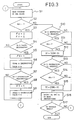
- Fig. 3 is a flow chart for explaining the operation of the apparatus in Fig. 2.
- Fig. 2 is a block diagram of a numerical control apparatus with a programmable mirror image function according to an embodiment of the present invention.
- Reference numeral 1 denotes a central processing unit (CPU); 2, a ROM for storing the program which controls the overall system of the numerical control apparatus; 3, a RAM for temporarily storing processed data; 4, an I/O port connected to a servo motor (not shown) or the like of a machine tool or the like; 5, a manual input unit; 6, a tape reader for reading a program from an NC program tape 7; and 8, a bus.
- mirror image function and mirror coordinate position are designated by statement (1):
- the mirror image instruction code G51.1 is programmed:
- the NC program tape 7 containing the programmed mirror image function is then placed in the tape reader 6.
- the tape is started, the numerical control apparatus performs processing in accordance with the flow of Fig. 3, and the processed data is supplied to a machine tool or the like.
- the CPU 1 fetches the program from the NC program tape 7 through the tape reader 6 in units of blocks (step S1).
- step S2 the CPU 1 checks whether or not the mirror image instruction code G51.1 has been entered. If NO in step S2, the CPU 1 jumps to step 10 and checks whether or not a shift instruction Xi for the X-axis has been entered. If NO in step S10, or if a flag FX is not set at logic "1" (step S11) even if YES in step S10 (the flag FX is set at logic "1" representing that the mirror image instruction is being executed upon generation of the mirror image function instruction to be described later), the CPU 1 supplies a normal NC instruction to the machine tool or the like.
- step 13 the CPU 1 checks whether or not a shift instruction Yi for the Y-axis has been entered. If NO in step S13, or if a flag FY is not set at logic "1" (step S14) even if YES in step S13, a normal NC instruction is supplied to the machine tool or the like.
- a normal NC instruction is supplied to the machine tool or the like.
- the operations in steps S1, S2, S10, S11, S13, S14 and S16 in Fig. 3 are performed to generate the normal shift instructions Xi and Yi.
- processing is executed through steps S1, S2, S10, and S13, and the read instruction outputs are generated in step S16.
- step S3 If the mirror image instruction code G51.1 is read in step S2, the X and Y flags FX and FY are cleared to zero (step S3).
- the CPU 1 checks in step S4 whether or not the mirror image instruction code G51.1 and the mirror position have been entered. If NO in step S4, the flow jumps to step S7. However, if YES in step S4, the X flag FX is set at logic "1" (step S5), and the input X-axis mirror position XM is stored (step S6). Similarly, the CPU 1 checks in step S7 whether or not a Y-axis mirror position has been entered. If NO in step S7, the flow returns to step S1.
- step S7 if YES in step S7, the Y flag FY is set at logic "1" and the Y-axis mirror position is stored (steps S8 and S9). Thereafter, the flow returns to step S1.
- the operations in steps S3 to S9 set the mirror image function and the corresponding mirror positions.
- step S1 The next program block is read (step S1), and the shift instruction Xi for the X-axis is read (steps S2 and S10).
- step S11 When the X flag FX is set at logic "1" (step S11), the mirror is located on the X-axis.
- the CPU 1 then performs the following processing in accordance with the X mirror position XM and the instruction value Xi read from the program (step S12).
- the new instruction value Xi is then stored.
- Xi-XM a difference between the X mirror coordinate and P1.
- the new instruction value Xi represents X coordinate position P1X in Fig. 1.
- X coordinate positions P2 and P3 are converted and X coordinate positions P2X and P3X are stored.
- step S13 When the shift instruction Yi for the Y-axis is designated (step S13) and the Y flag FY is set at logic "1" (step S14), that is, when the mirror is located along the Y-axis, the same processing as for the X-axis is performed to derive a new Y-axis instruction value Yi using equation (8):
- a mirror processing instruction is generated such that the mirror(s) is (are) located along one or both of the X- and Y-axes.
- the calculated value is generated as Xi in step S16. Since the Y flag FY is not set at logic "1", the shift instruction value Yi read from the program is generated without processing.
- the workpiece is thus machined to obtain the shape AX derived from the shape A when the mirror is placed at the mirror position XM as shown in Fig. 1.
- the machining instruction for the shape AY formed when the mirror is located at the mirror position YM is generated.
- both the flags FX and FY are set at logic "1"
- an X- and Y-axis mirror image function is exemplified.
- an X-, Y-, and Z-axis mirror image function can be used equally effectively in the same manner as described above.
Landscapes
- Engineering & Computer Science (AREA)
- Human Computer Interaction (AREA)
- Manufacturing & Machinery (AREA)
- Physics & Mathematics (AREA)
- General Physics & Mathematics (AREA)
- Automation & Control Theory (AREA)
- Numerical Control (AREA)
Claims (2)
Applications Claiming Priority (2)
| Application Number | Priority Date | Filing Date | Title |
|---|---|---|---|
| JP101757/84 | 1984-05-22 | ||
| JP59101757A JP2701022B2 (ja) | 1984-05-22 | 1984-05-22 | プログラマブルミラーイメージ機能を有する数値制御装置 |
Publications (3)
| Publication Number | Publication Date |
|---|---|
| EP0182918A1 EP0182918A1 (de) | 1986-06-04 |
| EP0182918A4 EP0182918A4 (de) | 1987-12-10 |
| EP0182918B1 true EP0182918B1 (de) | 1990-01-03 |
Family
ID=14309101
Family Applications (1)
| Application Number | Title | Priority Date | Filing Date |
|---|---|---|---|
| EP85902638A Expired EP0182918B1 (de) | 1984-05-22 | 1985-05-21 | Numerisch gesteuerte vorrichtung mit programmierbarer spiegelbildfunktion |
Country Status (5)
| Country | Link |
|---|---|
| US (1) | US4734864A (de) |
| EP (1) | EP0182918B1 (de) |
| JP (1) | JP2701022B2 (de) |
| DE (1) | DE3575212D1 (de) |
| WO (1) | WO1985005473A1 (de) |
Families Citing this family (11)
| Publication number | Priority date | Publication date | Assignee | Title |
|---|---|---|---|---|
| JPS63132309A (ja) * | 1986-11-25 | 1988-06-04 | Honda Motor Co Ltd | 工具通路デ−タの作成方法 |
| JP2759324B2 (ja) * | 1988-04-23 | 1998-05-28 | ファナック株式会社 | ロボットのミラーイメージ方法 |
| JPH01277909A (ja) * | 1988-04-29 | 1989-11-08 | Fanuc Ltd | スケーリング方法 |
| JPH02287802A (ja) * | 1989-04-28 | 1990-11-27 | Okuma Mach Works Ltd | 数値制御情報作成装置 |
| EP0433460A1 (de) * | 1989-06-07 | 1991-06-26 | Fanuc Ltd. | Nc-datenbearbeitung |
| JPH0340109A (ja) * | 1989-07-07 | 1991-02-20 | Fanuc Ltd | Ncデータ編集方式 |
| JPH04169905A (ja) * | 1990-11-01 | 1992-06-17 | Fanuc Ltd | 3次元レーザの座標変換方式 |
| EP0530384B1 (de) * | 1991-08-08 | 1996-01-03 | Siemens Aktiengesellschaft | Werkzeugmaschinensteuerung zur gleichzeitigen Bearbeitung von plattenförmigen Werkstücken mit mehreren Werkzeugen |
| KR0160672B1 (ko) * | 1995-02-13 | 1999-03-20 | 김광호 | 미러 이미지 제어를 위한 수치 제어 방법 및 장치 |
| JP3856531B2 (ja) * | 1997-06-26 | 2006-12-13 | 山形カシオ株式会社 | 座標データ変換方法及び装置 |
| CN104570947B (zh) * | 2015-01-26 | 2017-06-27 | 中北大学 | 一种阀门壳体系列零件的数控编程方法 |
Family Cites Families (10)
| Publication number | Priority date | Publication date | Assignee | Title |
|---|---|---|---|---|
| US4150427A (en) * | 1971-06-07 | 1979-04-17 | Houdaille Industries, Inc. | Machine tool data system and method |
| JPS4933081A (de) * | 1972-08-02 | 1974-03-26 | ||
| JPS507756A (de) * | 1973-05-23 | 1975-01-27 | ||
| US4314330A (en) * | 1973-12-03 | 1982-02-02 | Houdaille Industries, Inc. | Machine tool data system |
| GB1506224A (en) * | 1975-05-23 | 1978-04-05 | Crowther F | Apparatus for describing a path |
| JPH065486B2 (ja) * | 1981-03-26 | 1994-01-19 | 株式会社安川電機 | ロボットの軌跡制御方法 |
| JPS588310A (ja) * | 1981-07-07 | 1983-01-18 | Fanuc Ltd | 座標更新方式 |
| JPS58175003A (ja) * | 1982-04-07 | 1983-10-14 | Fanuc Ltd | 数値制御指令方式 |
| JPS58203511A (ja) * | 1982-05-21 | 1983-11-28 | Mitsubishi Electric Corp | 数値制御装置 |
| JPS60126712A (ja) * | 1983-12-14 | 1985-07-06 | Fanuc Ltd | Νcデ−タ作成方法 |
-
1984
- 1984-05-22 JP JP59101757A patent/JP2701022B2/ja not_active Expired - Lifetime
-
1985
- 1985-05-21 DE DE8585902638T patent/DE3575212D1/de not_active Expired - Lifetime
- 1985-05-21 WO PCT/JP1985/000277 patent/WO1985005473A1/ja not_active Ceased
- 1985-05-21 EP EP85902638A patent/EP0182918B1/de not_active Expired
-
1986
- 1986-01-21 US US06/823,498 patent/US4734864A/en not_active Expired - Lifetime
Also Published As
| Publication number | Publication date |
|---|---|
| JP2701022B2 (ja) | 1998-01-21 |
| JPS60246406A (ja) | 1985-12-06 |
| EP0182918A1 (de) | 1986-06-04 |
| DE3575212D1 (de) | 1990-02-08 |
| US4734864A (en) | 1988-03-29 |
| WO1985005473A1 (fr) | 1985-12-05 |
| EP0182918A4 (de) | 1987-12-10 |
Similar Documents
| Publication | Publication Date | Title |
|---|---|---|
| EP0182918B1 (de) | Numerisch gesteuerte vorrichtung mit programmierbarer spiegelbildfunktion | |
| US5793635A (en) | Numerically controlled machine tool and method | |
| US4396976A (en) | System for interfacing a computer to a machine | |
| EP0177164A2 (de) | Verfahren und Gerät zur Entwicklung numerischer Steuerungsprogramme | |
| HK1008445B (en) | Numerically controlled machine tool and method to re-execute a machining program after it has been stopped | |
| EP0103428B1 (de) | Programmiergerät für eine numerische Steuerung | |
| US4956594A (en) | Method of controlling a robot in accordance with load conditions | |
| EP0079388B1 (de) | Numerisches steuerverfahren | |
| EP0107794B1 (de) | Numerisches Steuerungssystem | |
| JP3199724B2 (ja) | 制御方法 | |
| EP0328663B1 (de) | Austauschverfahren für werkzeuge | |
| EP0507949B1 (de) | Verfahren zur Berechnung der axialen Richtung eines Werkzeuges. | |
| US4495561A (en) | Numerical control method | |
| JPS60127950A (ja) | 自動プログラミングにおける工具選別方法 | |
| KR0160672B1 (ko) | 미러 이미지 제어를 위한 수치 제어 방법 및 장치 | |
| JPH1083211A (ja) | 制御装置及びプログラミング方法 | |
| US5043645A (en) | NC statement preparing system | |
| JPH0158016B2 (de) | ||
| EP0445288A1 (de) | Betriebsbehandlungseinheit | |
| JPH0283709A (ja) | 数値制御装置 | |
| JPH0444281B2 (de) | ||
| JPS60222904A (ja) | 数値制御旋盤におけるワークの加工方法 | |
| JPH01152507A (ja) | Ncプログラム登録方式 | |
| JPH06102918A (ja) | 切削経路生成方法 | |
| JPS6345601A (ja) | 数値制御装置用電源装置 |
Legal Events
| Date | Code | Title | Description |
|---|---|---|---|
| PUAI | Public reference made under article 153(3) epc to a published international application that has entered the european phase |
Free format text: ORIGINAL CODE: 0009012 |
|
| 17P | Request for examination filed |
Effective date: 19860207 |
|
| AK | Designated contracting states |
Kind code of ref document: A1 Designated state(s): DE FR GB |
|
| A4 | Supplementary search report drawn up and despatched |
Effective date: 19871210 |
|
| 17Q | First examination report despatched |
Effective date: 19890516 |
|
| RBV | Designated contracting states (corrected) |
Designated state(s): DE |
|
| GRAA | (expected) grant |
Free format text: ORIGINAL CODE: 0009210 |
|
| AK | Designated contracting states |
Kind code of ref document: B1 Designated state(s): DE |
|
| REF | Corresponds to: |
Ref document number: 3575212 Country of ref document: DE Date of ref document: 19900208 |
|
| PLBE | No opposition filed within time limit |
Free format text: ORIGINAL CODE: 0009261 |
|
| STAA | Information on the status of an ep patent application or granted ep patent |
Free format text: STATUS: NO OPPOSITION FILED WITHIN TIME LIMIT |
|
| 26N | No opposition filed | ||
| PGFP | Annual fee paid to national office [announced via postgrant information from national office to epo] |
Ref country code: DE Payment date: 20040608 Year of fee payment: 20 |