EP0183013A1 - Dispositif pour former une pile d'imprimés arrivant et se chevauchant - Google Patents
Dispositif pour former une pile d'imprimés arrivant et se chevauchant Download PDFInfo
- Publication number
- EP0183013A1 EP0183013A1 EP85112451A EP85112451A EP0183013A1 EP 0183013 A1 EP0183013 A1 EP 0183013A1 EP 85112451 A EP85112451 A EP 85112451A EP 85112451 A EP85112451 A EP 85112451A EP 0183013 A1 EP0183013 A1 EP 0183013A1
- Authority
- EP
- European Patent Office
- Prior art keywords
- stack
- outlet
- wheel
- conveyor
- feed conveyor
- Prior art date
- Legal status (The legal status is an assumption and is not a legal conclusion. Google has not performed a legal analysis and makes no representation as to the accuracy of the status listed.)
- Withdrawn
Links
- 230000015572 biosynthetic process Effects 0.000 title claims abstract description 17
- 230000002093 peripheral effect Effects 0.000 claims description 2
- 230000002441 reversible effect Effects 0.000 description 6
- 230000005540 biological transmission Effects 0.000 description 2
- 230000000717 retained effect Effects 0.000 description 2
- 238000013459 approach Methods 0.000 description 1
- 230000015556 catabolic process Effects 0.000 description 1
- 238000006731 degradation reaction Methods 0.000 description 1
- 230000001419 dependent effect Effects 0.000 description 1
- 238000004519 manufacturing process Methods 0.000 description 1
- 238000004904 shortening Methods 0.000 description 1
- 238000004804 winding Methods 0.000 description 1
Images

Classifications
-
- B—PERFORMING OPERATIONS; TRANSPORTING
- B65—CONVEYING; PACKING; STORING; HANDLING THIN OR FILAMENTARY MATERIAL
- B65H—HANDLING THIN OR FILAMENTARY MATERIAL, e.g. SHEETS, WEBS, CABLES
- B65H29/00—Delivering or advancing articles from machines; Advancing articles to or into piles
- B65H29/66—Advancing articles in overlapping streams
- B65H29/6645—Advancing articles in overlapping streams buffering an overlapping stream of articles
-
- B—PERFORMING OPERATIONS; TRANSPORTING
- B65—CONVEYING; PACKING; STORING; HANDLING THIN OR FILAMENTARY MATERIAL
- B65H—HANDLING THIN OR FILAMENTARY MATERIAL, e.g. SHEETS, WEBS, CABLES
- B65H31/00—Pile receivers
-
- B—PERFORMING OPERATIONS; TRANSPORTING
- B65—CONVEYING; PACKING; STORING; HANDLING THIN OR FILAMENTARY MATERIAL
- B65H—HANDLING THIN OR FILAMENTARY MATERIAL, e.g. SHEETS, WEBS, CABLES
- B65H33/00—Forming counted batches in delivery pile or stream of articles
- B65H33/06—Forming counted batches in delivery pile or stream of articles by displacing articles to define batches
- B65H33/08—Displacing whole batches, e.g. forming stepped piles
Definitions
- the present invention relates to a device according to the preamble of claim 1.
- a device is known for example from DE-OS 2518 374 (published on December 11, 1975).
- stable, coiled stacks can be produced from the flat structures, even if they occur in very rapid succession, the capacity of which is many times greater than that of conventional, essentially cuboid stacks.
- Another advantage of a coiled stack can be seen in the fact that the scale formation, albeit curved, is retained in the stack itself, which enables the scale formation to be restored when the stack is dismantled.
- the proposed device has the features defined in the characterizing part of patent claim 1.
- the stack can also be dismantled from above by lifting the separating agent in that the individual turns are "peeled off", even if the successive specimens in the resulting scale formation do not have the usual reference position to one another. While in the usual reference position the leading edge of each copy overlaps the trailing edge of the previous copy, when a stack made with the proposed device is dismantled from above, the trailing edge of each copy overlaps the leading edge of the following copy, as if it were when the Stack of scale formation fed in to a certain extent reduced in "reverse gear".
- the usual reference position can easily be restored by simple devices that are known per se.
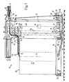
- the device 10 shown in FIGS. 1 and 2 are supplied with flat structures, here newspapers 11, by means of a single conveyor 12 which is only indicated schematically.
- the individual conveyor 12 is described, for example, in CH-PS 592,562, which is largely identical in content to US-PS 3,955,667, so that a more detailed description is unnecessary here, especially since the individual conveyor 12 only shows its discharge end 13.
- the newspapers 11 released at the discharge end 13 arrive at a transfer belt 14 which is driven in the same direction and essentially at the same speed as that of the individual conveyor 12.
- a scale formation is formed on the transfer belt 14 from the newspapers 11, in which the leading edge of each newspaper is its bundle or fold, which overlaps the trailing edge (flower) of the preceding newspaper.
- the newspapers accumulating from the transfer belt 14 arrive, maintaining the scale formation, on a feed conveyor 15, the conveyor-active strand of which is initially guided in the same direction as the transfer belt 14 by a deflection roller 16 runs, then vertically downward around a deflection rail 17, around a further deflection roller 18 again horizontally from right to left (in FIG. 1) and finally ends at the outlet 20 formed by a further deflection roller 19.
- the empty, returning run of the feed conveyor 15 leads vertically downwards from the deflection roller 19 via a roller 21 arranged in the vicinity of the deflection roller 18, around a drive roller 22 and from there vertically upwards around a further deflection roller 23 and again to the deflection roller 16 .
- the deflection rollers 18 and roller 21 are mounted on a frame 24, from which frame also an outrigger (not shown) carrying the deflection roller 19 at the outlet 20 starts.
- the frame 24 is vertically guided, so corresponds in this respect to the auxiliary frame described with reference to FIG. 3A of DE-OS 25 18 374.8 with the reference number 58.
- the vertical guide rails for the frame 24 are not shown here.
- the drive roller 22 for the feed conveyor 15 is connected via a chain 28 to a motor 29, the speed of which is preferably infinitely variable in order to adapt the conveying speed of the conveyor 15 to that of the individual conveyor 12.
- the drive roller 27 is coupled via a chain 30 to a reversible motor 31, the control of which will be described below.
- Both motors 29, 31 are mounted on a platform 32, which is at the lower end of a vertical column 33 protrudes laterally and is attached to it.
- the column 33 is rotatably supported at 34, 35 and 36.
- a boom 37 is attached, the vertical guide rails (not shown) for the frame 24 extending between the latter and the platform 32.
- a pressure belt 38 is also mounted in the delivery arm 37, which serves primarily to press the newspapers 11 onto the section of the conveyor-active strand of the feed conveyor that runs between the deflection rail 17 and the deflection roller 18. Since this section of the active conveyor strand is of variable length, the pressure belt 38 runs around a length compensation device. As can be seen in FIG.
- the band 38 runs around the deflecting roller which can be displaced vertically with the frame 24, then around a roller 39 which is fixedly but rotatably mounted in the arm 37, from there around a first deflecting roller 40, around a second deflecting roller 41, around a third deflecting roller 42 and finally around a larger fourth deflecting roller 43 arranged above the starting area of the active conveyor section of the feed conveyor 15.
- the rollers 39, 41 and 43 are fixedly but rotatably mounted in the boom 37
- the rollers 40, 42 rotatably mounted in a roller frame horizontally displaceable against the action of a gas spring 14 in the boom 37.
- the roller frame 45 can be moved up to the position shown in dashed lines in Fig. 1 and thereby releases as much length of the pressure belt 38 as is necessary to follow the downward movement of the frame 24, while the gas spring 44 for a shortening during its upward movement the active length of the pressure belt 38 provides.
- a stack carrier 46 in the form of a turntable is located under the outlet 20 of the feed conveyor 15. At his The underside of the stack carrier 46 is provided with rollers 47 arranged at uniform circumferential intervals and with laterally effective guide rollers 48 which are supported or guided by a guide rail 49 which describes a circular path and is L-shaped in cross section.
- a friction wheel 150 which is rotatably mounted at the free end of an arm 151 anchored to the platform 32, also engages on the underside of the stack carrier 46.
- the friction wheel 150 is positively connected to the drive roller 22 via two chains 152.
- the circumferential speed of the friction wheel 150 is thus always strictly proportional or - with the corresponding transmission ratios - even the same as the conveying speed of the feed conveyor 15.
- the friction wheel 150 drives the stack carrier 46 and the stack formed thereon in the direction of the arrow 53 about a vertical axis of rotation 54. As will be shown, however, the speed at which the stack carrier 46 is driven depends on the current position of the outlet 20 and thus of the friction wheel 150 with respect to the axis of rotation 54.
- both the platform 32 with the motors 29, 31 and the outrigger 151 extending from the platform 32, the outrigger 37 with the feed conveyor 15 and the pressure belt 38 and the frame 24 with the column 33 can be rotated.
- a gear 56 sits on the column 33 in the area of its lower end, which meshes with the driven pinion 57 of an angular gear 58, to which a reversible motor 59, for example a stop motor or a stepper motor, is flanged.
- the Reduction ratio between the pinion 57 and the gear 56 is selected so that the pinion 57 is less in the intended rotation of the column 33 in one and in the other direction by an angle of rotation given by the limited pivoting angle of the feed conveyor 15 (see FIG.
- the current rotational position of the column 33 can thus also be clearly derived from the respective rotational position of the pinion 57.
- the pinion 57 is therefore connected in a rotationally fixed manner to a cam disk 60, the position of which is sensed by stationary electrical signal transmitters 61, for example microswitches, which signal transmitters reverse the motor 59.
- a swing arm 63 which is only indicated schematically and has a freely rotatable wheel 62 at its end, is articulated on the frame 24 and scans the current height of the stack 55.
- the rocker arm 63 actuates an electrical height transmitter 64, which in turn switches on or stops the motor 31 for the height adjustment of the frame 24 in one or the other direction of rotation via a line 65 and a reversing switch 66.
- the speed of the stack carrier 46 is variable. This speed is higher, the smaller the distance of the friction wheel 150 in front of the axis of rotation 54 and vice versa.
- the current rotational speed of the stack carrier 46 or the stack 55 at the point immediately below the outlet 20 of the feed conveyor 15 is adapted to the conveying speed of the latter. This ensures that the distance between successive newspapers 11, the so-called "scale spacing" in the stack 55 remains constant, regardless of whether the scale formation is deposited in the region of the circumference of the stack carrier or in the vicinity of its axis of rotation.
- each spiral turn consists of a spiral with a plurality of spiral turns running alternately from outside to inside and from inside to outside.
- the outline of a spiral of the stack is shown with the dashed line 79, which in turn corresponds to a turn of the spiral stack 55.
- Such a stack has a very large capacity and is very stable. Because of its structure, its dismantling (unstacking) is a delicate matter, especially if this dismantling is to be done mechanically and while maintaining the (still present in the stack) scale formation.
- the device shown is provided with a dispensing device which continuously releases a thread-like or band-shaped separating agent during stacking, and which runs along with the scale formation to be stacked, so that one between each spiral turn of the stacked scale formation Helix turn of the release agent comes to rest.
- a supply spool 67 is rotatably mounted on the frame 24, of which (see FIG. 2) by means of a Pull-off wheel 68, to which two freely rotatable pressure rollers 69, 69 'are assigned, a release agent, for example a narrow, tear-resistant and flexible band 70, is continuously pulled off.
- the pull-off wheel 68 is drive-connected via an angular gear 71 (FIG. 2) to the deflecting roller 19 at the outlet 20 of the feed conveyor 15, the transmission ratio of the angular gear 71 being selected such that the peripheral speed of the pull-off wheel 68 corresponds to the conveying speed at the outlet 20.
- the separating belt 70 is thus taken along by the newspapers which accumulate over it in scale form, so that the separating belt 70 in the stack has essentially the same course as the spiral winding lying directly above it. This is indicated in FIG. 2 with the spiral arcs 72 shown in dash-dot lines.
Landscapes
- Engineering & Computer Science (AREA)
- Mechanical Engineering (AREA)
- Discharge By Other Means (AREA)
- Separation, Sorting, Adjustment, Or Bending Of Sheets To Be Conveyed (AREA)
Applications Claiming Priority (2)
| Application Number | Priority Date | Filing Date | Title |
|---|---|---|---|
| CH4929/84A CH664137A5 (de) | 1984-10-15 | 1984-10-15 | Einrichtung zum herstellen eines gewendelten stapels aus auf einem zufoerderer kontinuierlich in einer schuppenformation anfallenden flaechengebilden. |
| CH4929/84 | 1984-10-15 |
Publications (1)
| Publication Number | Publication Date |
|---|---|
| EP0183013A1 true EP0183013A1 (fr) | 1986-06-04 |
Family
ID=4284990
Family Applications (1)
| Application Number | Title | Priority Date | Filing Date |
|---|---|---|---|
| EP85112451A Withdrawn EP0183013A1 (fr) | 1984-10-15 | 1985-10-02 | Dispositif pour former une pile d'imprimés arrivant et se chevauchant |
Country Status (5)
| Country | Link |
|---|---|
| EP (1) | EP0183013A1 (fr) |
| JP (1) | JPH0662239B2 (fr) |
| CA (1) | CA1244495A (fr) |
| CH (1) | CH664137A5 (fr) |
| ZA (1) | ZA857623B (fr) |
Cited By (4)
| Publication number | Priority date | Publication date | Assignee | Title |
|---|---|---|---|---|
| EP0384147A1 (fr) * | 1989-02-22 | 1990-08-29 | Ferag AG | Procédé et appareil pour l'emmagasinage intermédiaire de produits d'imprimerie pliés, à plusieurs feuilles, comme journaux, magazines et parties de ceux-ci |
| EP0359727A3 (fr) * | 1988-09-15 | 1991-02-20 | Idab-Wamac Aktiebolag | Une méthode et des moyens pour stocker temporairement une succession de journaux ou similaires |
| EP1253098A1 (fr) * | 2001-04-23 | 2002-10-30 | Grapha-Holding AG | Appareil pour la manutention des produits imprimés alimentés vers un dispositif d'empilage |
| WO2005044707A1 (fr) * | 2003-11-05 | 2005-05-19 | Sten Wallsten | Dispositif de stockage |
Citations (3)
| Publication number | Priority date | Publication date | Assignee | Title |
|---|---|---|---|---|
| DE2518372A1 (de) * | 1974-05-28 | 1975-12-11 | Ferag Ag | Vorrichtung zum entstapeln eines wendelfoermig aufgebauten stapels von druckprodukten |
| CH587766A5 (fr) * | 1974-06-17 | 1977-05-13 | Evg Entwicklung Verwert Ges | |
| DE3001968A1 (de) * | 1979-01-23 | 1980-07-31 | Faltin Hans G | Palette mit darauf gelagerten faltbogen |
-
1984
- 1984-10-15 CH CH4929/84A patent/CH664137A5/de not_active IP Right Cessation
-
1985
- 1985-10-02 EP EP85112451A patent/EP0183013A1/fr not_active Withdrawn
- 1985-10-03 ZA ZA857623A patent/ZA857623B/xx unknown
- 1985-10-11 CA CA000492796A patent/CA1244495A/fr not_active Expired
- 1985-10-14 JP JP60228560A patent/JPH0662239B2/ja not_active Expired - Lifetime
Patent Citations (3)
| Publication number | Priority date | Publication date | Assignee | Title |
|---|---|---|---|---|
| DE2518372A1 (de) * | 1974-05-28 | 1975-12-11 | Ferag Ag | Vorrichtung zum entstapeln eines wendelfoermig aufgebauten stapels von druckprodukten |
| CH587766A5 (fr) * | 1974-06-17 | 1977-05-13 | Evg Entwicklung Verwert Ges | |
| DE3001968A1 (de) * | 1979-01-23 | 1980-07-31 | Faltin Hans G | Palette mit darauf gelagerten faltbogen |
Cited By (6)
| Publication number | Priority date | Publication date | Assignee | Title |
|---|---|---|---|---|
| EP0359727A3 (fr) * | 1988-09-15 | 1991-02-20 | Idab-Wamac Aktiebolag | Une méthode et des moyens pour stocker temporairement une succession de journaux ou similaires |
| EP0384147A1 (fr) * | 1989-02-22 | 1990-08-29 | Ferag AG | Procédé et appareil pour l'emmagasinage intermédiaire de produits d'imprimerie pliés, à plusieurs feuilles, comme journaux, magazines et parties de ceux-ci |
| US5048264A (en) * | 1989-02-22 | 1991-09-17 | Ferag Ag | Process and apparatus for the temporary storage of multi-sheeted, folded printing products, such as newspapers, periodicals and parts thereof |
| EP1253098A1 (fr) * | 2001-04-23 | 2002-10-30 | Grapha-Holding AG | Appareil pour la manutention des produits imprimés alimentés vers un dispositif d'empilage |
| US7192028B2 (en) | 2001-04-23 | 2007-03-20 | Grapha-Holding Ag | Device for processing printed products supplied to a stacking device |
| WO2005044707A1 (fr) * | 2003-11-05 | 2005-05-19 | Sten Wallsten | Dispositif de stockage |
Also Published As
| Publication number | Publication date |
|---|---|
| CH664137A5 (de) | 1988-02-15 |
| ZA857623B (en) | 1986-05-28 |
| JPS6198535A (ja) | 1986-05-16 |
| CA1244495A (fr) | 1988-11-08 |
| JPH0662239B2 (ja) | 1994-08-17 |
Similar Documents
| Publication | Publication Date | Title |
|---|---|---|
| DE3404459C2 (fr) | ||
| DE2852603C3 (de) | Vorrichtung zum Erzeugen einer vorbestimmten Lücke in einem sich schuppenartig überlappenden Bogenstrom | |
| DE3221153C2 (fr) | ||
| EP0498962B1 (fr) | Procédé et dispositif pour réaliser une bobine | |
| DE8117782U1 (de) | Vorrichtung zur Aufnahme von blattförmigem nachgiebigen Gut | |
| CH660353A5 (de) | Verfahren und vorrichtung zum unterteilen eines schuppenstromes aus druckbogen in teilschuppen. | |
| EP0298267B1 (fr) | Dispositif pour enrouler ou dérouler des produits imprimés, en formation imbriquée, arrivant ou emportés par un transporteur | |
| EP0229888B1 (fr) | Dispositif pour stocker des imprimés progressant en courants d'articles se chevauchant | |
| EP1622778B1 (fr) | Systeme pour inserer des feuilles dans une enveloppe | |
| DE2518374C2 (de) | Einrichtung zum Bilden eines wendelförmigen Stapels aus kontinuierlich in einem Schuppenstrom anfallenden Druckprodukten | |
| DE2658294A1 (de) | Vorrichtung zum abwickeln von aus ventilsaecken bestehenden schuppenbandrollen | |
| DE19533086A1 (de) | Verfahren und Vorrichtung zum Stapeln von flächigen Erzeugnissen, insbesondere Druckereiprodukten | |
| DE2644906C2 (de) | Einrichtung zum Zuführen von Druckprodukten an einen Stapeltisch | |
| EP0054735A2 (fr) | Dispositif de fabrication de rouleaux de bandes formées à partir de feuilles souples imbriqueés | |
| EP0300179A1 (fr) | Procédé et dispositif pour alimenter un séparateur avec des imprimés | |
| DE1436485B2 (de) | Vorrichtung zum Befördern, Stapeln und Zählen von Druckschriften | |
| DE3407804C2 (fr) | ||
| EP0493669A2 (fr) | Dispositif situé entre un métier à retordre et une station d'alimentation de cannettes pour enlever des tubes mis sur supports individuels | |
| CH664137A5 (de) | Einrichtung zum herstellen eines gewendelten stapels aus auf einem zufoerderer kontinuierlich in einer schuppenformation anfallenden flaechengebilden. | |
| EP0161415B1 (fr) | Dispositif de formation d'une pile en hélice à partir d'un courant d'articles plans se chevauchant | |
| DE2519341C2 (de) | Vorrichtung zum Beladen mehrerer in einem Ablagegestell angeordneter Tragplatten mit blattartigen Gegenständen | |
| EP0316563B1 (fr) | Dispositif d'enroulage d'une pluralité de feuilles imprimées | |
| EP0384147B1 (fr) | Procédé et appareil pour l'emmagasinage intermédiaire de produits d'imprimerie pliés, à plusieurs feuilles, comme journaux, magazines et parties de ceux-ci | |
| DE69720827T2 (de) | Vorrichtung zum Zuführen von Zuschnitten in einer Zigarettenverpackungsmaschine | |
| DE3414718A1 (de) | Einrichtung zum zwischenspeichern von druckprodukten |
Legal Events
| Date | Code | Title | Description |
|---|---|---|---|
| PUAI | Public reference made under article 153(3) epc to a published international application that has entered the european phase |
Free format text: ORIGINAL CODE: 0009012 |
|
| AK | Designated contracting states |
Kind code of ref document: A1 Designated state(s): DE FR GB IT |
|
| STAA | Information on the status of an ep patent application or granted ep patent |
Free format text: STATUS: THE APPLICATION HAS BEEN WITHDRAWN |
|
| 18W | Application withdrawn |
Withdrawal date: 19860605 |
|
| RIN1 | Information on inventor provided before grant (corrected) |
Inventor name: REIST, WALTER |