EP0183082A1 - Table-barbecue - Google Patents
Table-barbecue Download PDFInfo
- Publication number
- EP0183082A1 EP0183082A1 EP85113910A EP85113910A EP0183082A1 EP 0183082 A1 EP0183082 A1 EP 0183082A1 EP 85113910 A EP85113910 A EP 85113910A EP 85113910 A EP85113910 A EP 85113910A EP 0183082 A1 EP0183082 A1 EP 0183082A1
- Authority
- EP
- European Patent Office
- Prior art keywords
- hollow base
- air
- grill
- ring
- table according
- Prior art date
- Legal status (The legal status is an assumption and is not a legal conclusion. Google has not performed a legal analysis and makes no representation as to the accuracy of the status listed.)
- Granted
Links
- 238000010438 heat treatment Methods 0.000 claims description 15
- 238000010304 firing Methods 0.000 claims description 9
- 238000007373 indentation Methods 0.000 claims description 5
- 230000002441 reversible effect Effects 0.000 claims description 2
- 238000002485 combustion reaction Methods 0.000 description 3
- 125000006850 spacer group Chemical group 0.000 description 3
- 239000000969 carrier Substances 0.000 description 2
- 238000009408 flooring Methods 0.000 description 2
- RYGMFSIKBFXOCR-UHFFFAOYSA-N Copper Chemical compound [Cu] RYGMFSIKBFXOCR-UHFFFAOYSA-N 0.000 description 1
- ATJFFYVFTNAWJD-UHFFFAOYSA-N Tin Chemical compound [Sn] ATJFFYVFTNAWJD-UHFFFAOYSA-N 0.000 description 1
- 239000003610 charcoal Substances 0.000 description 1
- 229910052802 copper Inorganic materials 0.000 description 1
- 239000010949 copper Substances 0.000 description 1
- 239000002737 fuel gas Substances 0.000 description 1
- 239000002184 metal Substances 0.000 description 1
- 229910052751 metal Inorganic materials 0.000 description 1
- 238000000034 method Methods 0.000 description 1
- 238000000465 moulding Methods 0.000 description 1
- 230000000630 rising effect Effects 0.000 description 1
- 230000036642 wellbeing Effects 0.000 description 1
Images

Classifications
-
- F—MECHANICAL ENGINEERING; LIGHTING; HEATING; WEAPONS; BLASTING
- F24—HEATING; RANGES; VENTILATING
- F24B—DOMESTIC STOVES OR RANGES FOR SOLID FUELS; IMPLEMENTS FOR USE IN CONNECTION WITH STOVES OR RANGES
- F24B7/00—Stoves, ranges or flue-gas ducts, with additional provisions for convection heating
- F24B7/02—Stoves, ranges or flue-gas ducts, with additional provisions for convection heating with external air ducts
- F24B7/025—Stoves, ranges or flue-gas ducts, with additional provisions for convection heating with external air ducts with forced circulation
-
- A—HUMAN NECESSITIES
- A47—FURNITURE; DOMESTIC ARTICLES OR APPLIANCES; COFFEE MILLS; SPICE MILLS; SUCTION CLEANERS IN GENERAL
- A47J—KITCHEN EQUIPMENT; COFFEE MILLS; SPICE MILLS; APPARATUS FOR MAKING BEVERAGES
- A47J37/00—Baking; Roasting; Grilling; Frying
- A47J37/06—Roasters; Grills; Sandwich grills
- A47J37/07—Roasting devices for outdoor use; Barbecues
- A47J37/0781—Barbecue tables, e.g. central grilling areas surrounded by an eating table
Definitions
- the invention relates to a grill table with a table top supported on a central hollow base, which has a central opening into which a firing container is inserted, above which the grillage is located, air inlet openings being provided between the table top and the hollow base, which open the annular space between the hollow base and Connect the combustion container to the outside air area below the table top.
- a grill table of this type is known from DE-GM 77 02 274.
- the air inlet openings serve to introduce the air located below the table top through the perforated container base into the furnace as combustion air. It is not possible to control this air volume.
- the invention has for its object to design the known grill table in such a way that the air flow in the grill table area influences independently of the burning process in the furnace and can be used in particular as warm air heating in the immediate grill table environment.
- This measure has the advantage that, on the one hand, the heat - • line heated table top can be cooled and kept at a certain temperature by means of the sucked-in air, while on the other hand this air forcibly brushes along the furnace and can ultimately be used as a warm air curtain or room heating for the people sitting around the grill table in cooler seasons.
- the furnace is closed at the bottom.
- the combustion air for the grill coals contained in it comes in from the side or from above, while the hot fuel gases rise vertically.
- the hollow base have a circumferential perforated ring in the vicinity of its lower edge, which is covered by a rotating ring having an identical perforated ring. If the rotating ring is positioned so that the holes lie on top of one another and are thus open, the warm air exiting into the footwell forms a pleasant, rising veil or warms the room in which the grill table and the people sitting around it are located.
- a number of air flow channels extending radially to the vertical axis of the hollow foot and extending from the interior of the hollow foot can also be formed under the base supporting the hollow foot and can be shut off by means of a rotary valve. If the rotary valve is open, the warm air can flow so far from the grill table through the air flow channels in the warmer season be carried away so that it is no longer perceived as annoying. If, for example, a pavilion is built around the grill table, the air can be led out of it. However, it is also possible to have the outlet openings of the air flow ducts end just behind the people sitting around the grill table or within the outer walls of the aforementioned pavilion, as a result of which space heating is achieved in the back area.
- the rotary ring and the rotary slide valve are preferably coupled to one another by a common actuating member in such a way that in one end position of the actuating member the holes of the opened ring of holes and the air flow channels are blocked, while in the other end position the holes are closed and the air flow channels are open.
- the intermediate position of the actuator With the intermediate position of the actuator, the total air flow can be divided in terms of quantity depending on the season and well-being.
- the furnace be penetrated by a number of radially arranged air heating tubes which extend between a central indentation of the container bottom and the container side wall.
- the pipes are expediently inserted into corresponding openings in the furnace welds with their ends open and flush with the outer surface of the container.
- the forced air thus not only sweeps along the outer surface of the furnace, but also flows through the air heating pipes surrounded by the embers, so that it heats up much more intensely. This enables, for example, the effective heating of a pavilion surrounding the grill table even at relatively low outside temperatures.
- the fan coaxially installed in the hollow base does not convey downwards, but sucks in from below and conveys upwards, so that the heat of the young embers is absorbed in the air heating pipes and hot air escapes from the air inlet openings, which the tabletop warmed from below.
- the fan coaxially installed in the hollow base does not convey downwards, but sucks in from below and conveys upwards, so that the heat of the young embers is absorbed in the air heating pipes and hot air escapes from the air inlet openings, which the tabletop warmed from below.
- it is sufficient to operate the fan in the opposite direction for only 30 seconds in order to give the grill table, in which there are recessed dishes, the desired temperature.
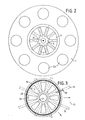
- the grill table shown has a circular table top 1, which is supported centrally by a cylindrical hollow foot 3 via a plurality of spacers 2. As a result of the spacers 2, the upper edge of the hollow base 3 is below the table top 1, which results in slot-shaped air inlet openings 4.
- the table top 1 has a round central opening, the diameter of which is almost equal to the inside width of the hollow base 3.
- a cylindrical furnace 5 is suspended in this table top opening. It has a flange on top, which rests on the table top 1.
- the bottom of the firing container 5 has a truncated cone-shaped, upstanding indentation 6. Between the jacket of this indentation 6 and the jacket of the firing vessel 5 extend ten star-shaped air heating tubes 7, which rise from the inside to the outside. The open ends of the air heating tubes 7 are welded into corresponding openings in the lateral surfaces and are almost flush with them. Charcoal coals are filled into the firing container 5 up to about half the height and ignited. There is an annular gap 8 between the jacket of the furnace 5 and the hollow base 3.
- a fan 10 is installed in the hollow base 3 below the furnace by means of an intermediate ring 9. Its axis runs vertically and it is surrounded by a guide tube 11.
- the drive motor is designed for right and left rotation.
- the hollow base 3 has air outlet openings 12 which are regularly distributed over its entire circumference.
- This ring of holes is surrounded on the outside by a rotating ring 13 which has corresponding openings. By turning this rotary ring 13, the air outlet openings 12 can thus be closed and opened continuously.
- the air outlet device described so far in itself fulfills the need.
- additional air flow channels can be provided, which are described below.
- the grill table shown or its hollow base 3 stands with its lower flange on a plate-shaped floor covering 14. This is supported by star-shaped supports 15, in particular profiled tubes, which start from a hub ring 16 arranged centrally under the hollow base 3, to which they are attached.
- Sector-shaped air flow channels 17 result between the carriers 15.
- the rotary valve consists of a hard disk 18, which covers the annular passage opening between the hub ring 16 and the edge of the opening of the floor covering 14.
- This hard disk 18 has eight trapezoidal windows 19 which are arranged in a regular star shape.
- the rotating plate 20 and the rotating ring 13 are connected to one another by means of a grip piece 22 which reaches through a horizontal slot in the hollow base 3 and can be rotated back and forth together between two end positions.
- the arrangement is preferably such that in one end position the rotary valve is closed and thus the air supply to the air flow channels 17 is blocked, while the air outlet openings 12 are free.
- the rotary valve In the other end position, the rotary valve is open and the air outlet openings 12 are closed. In the intermediate positions, the air flows can be distributed as desired.
- the air flow channels 17 can lead radially away from the grill table so that the people sitting around the table are no longer bothered by the exiting warm air (summer operation). However, if the grill table is converted from a small lounge, the air flow channels 17 can be in the back area of the people, however inside the building through the flooring 14 are led up again.
- the copper table top 1 has eight trough-like depressions 23, which are preferably arranged at equal circumferential intervals. These trough-like depressions are neither provided with a tin support so that they can be used directly as dining troughs, or suitable metal plates are provided in these depressions.
- a vertically standing support rod 24 is attached to the upper end of the indentation 6 of the furnace.
- a sliding sleeve 25 is guided, which carries a round grill 26 at its lower end.
- the outside diameter of this grillage is slightly smaller than the inside diameter of the firing container 5.
- a receiving shell 27 is fastened to the sliding sleeve 25. It is used to stock the goods to be grilled.
- a locking device 28 is provided, which contains a locking bolt. This engages in one of a larger number of circumferential grooves of the support rod 24, which are arranged at different heights. As a result, the height of the grill grate 26 can be adjusted as desired, depending on the instant heat of the embers, but the grill grate and the receiving shell remain rotatable.
- the grill table described works as follows: If the firing container 5 warms up slowly after igniting the charcoals, but the table top 1 is still cold, you can quickly start up the fan 10 with the direction of delivery upwards (contrary to the arrows shown) heat. The air is sucked in through the air outlet openings 12 and forced through the air heating pipes or the gap 8, so that hot air emerges at the air inlet openings 4 and flows along the underside of the table top.
Landscapes
- Engineering & Computer Science (AREA)
- Chemical & Material Sciences (AREA)
- Combustion & Propulsion (AREA)
- Mechanical Engineering (AREA)
- General Engineering & Computer Science (AREA)
- Food Science & Technology (AREA)
- Baking, Grill, Roasting (AREA)
- Electric Stoves And Ranges (AREA)
- Drying Of Solid Materials (AREA)
- Devices For Use In Laboratory Experiments (AREA)
Priority Applications (1)
| Application Number | Priority Date | Filing Date | Title |
|---|---|---|---|
| AT85113910T ATE32423T1 (de) | 1984-11-24 | 1985-10-31 | Grilltisch. |
Applications Claiming Priority (2)
| Application Number | Priority Date | Filing Date | Title |
|---|---|---|---|
| DE3442971 | 1984-11-24 | ||
| DE3442971 | 1984-11-24 |
Publications (2)
| Publication Number | Publication Date |
|---|---|
| EP0183082A1 true EP0183082A1 (fr) | 1986-06-04 |
| EP0183082B1 EP0183082B1 (fr) | 1988-02-10 |
Family
ID=6251112
Family Applications (1)
| Application Number | Title | Priority Date | Filing Date |
|---|---|---|---|
| EP85113910A Expired EP0183082B1 (fr) | 1984-11-24 | 1985-10-31 | Table-barbecue |
Country Status (3)
| Country | Link |
|---|---|
| EP (1) | EP0183082B1 (fr) |
| AT (1) | ATE32423T1 (fr) |
| DE (1) | DE3561575D1 (fr) |
Cited By (9)
| Publication number | Priority date | Publication date | Assignee | Title |
|---|---|---|---|---|
| EP0640798A1 (fr) * | 1993-08-10 | 1995-03-01 | SCHACHT, Paul | Système d'évacuation |
| WO1996001395A1 (fr) * | 1994-07-05 | 1996-01-18 | Fairmount Commercial Enterprises Pty. Limited | Appareil de cuisson a plateau de table integre |
| DE202009015435U1 (de) * | 2009-11-12 | 2011-03-24 | Schmidt, Daniel | Erwärmungsvorrichtung für den Außenbereich Beheizbarer Bistrotisch für den Außenbereich für die Gastronomie und den Privatbereich |
| DE202010017123U1 (de) * | 2010-12-28 | 2012-04-02 | Staedtler + Uhl Kg | Beheizbarer Tisch |
| US20120210994A1 (en) * | 2011-02-23 | 2012-08-23 | Mike Peter Gulotta | Apparatus and method for heat distribution from gas fire |
| EP3038505A4 (fr) * | 2013-08-29 | 2016-08-24 | Brand Developers Aust Pty Ltd | Appareil de grillade |
| KR101900223B1 (ko) | 2018-06-25 | 2018-09-18 | 문성현 | 바베큐 테이블 |
| EP4098157A1 (fr) * | 2021-05-31 | 2022-12-07 | Confort Domo France | Table-brasero |
| IT202300015132A1 (it) | 2023-07-19 | 2025-01-19 | Ecoclima S R L Di Bruno | Tavolo con barbecue integrato |
Citations (10)
| Publication number | Priority date | Publication date | Assignee | Title |
|---|---|---|---|---|
| DE7702274U1 (fr) * | Kleine, Peter, 4619 Bergkamen-Ruenthe | |||
| FR726200A (fr) * | 1930-11-15 | 1932-05-24 | Poêle à air chaud pulsé pour le chauffage rapide des locaux | |
| US2058254A (en) * | 1934-09-10 | 1936-10-20 | Paul C Pederson | Heating appliance |
| FR1003548A (fr) * | 1947-01-21 | 1952-03-19 | Essor Economique | Perfectionnements apportés aux moyens pour le chauffage de locaux, en particulier pour l'habitation, notamment pour le chauffage des locaux préfabriqués de ce genre |
| US2742892A (en) * | 1953-08-04 | 1956-04-24 | Gen Machine Company Inc | Fireplace heater unit |
| US3327697A (en) * | 1965-09-24 | 1967-06-27 | Berlant Sigmund | Cooking device provided with air curtain |
| FR1570591A (fr) * | 1968-03-22 | 1969-06-13 | ||
| DE7404217U (de) * | 1974-02-07 | 1974-05-02 | Streicher M | Grilltisch |
| FR2288504A1 (fr) * | 1975-06-11 | 1976-05-21 | Selva Guy | Perfectionnements aux appareils de cuisson du genre des barbecues |
| US4481408A (en) * | 1983-11-07 | 1984-11-06 | Scheufler John H | Cooking apparatus |
-
1985
- 1985-10-31 EP EP85113910A patent/EP0183082B1/fr not_active Expired
- 1985-10-31 DE DE8585113910T patent/DE3561575D1/de not_active Expired
- 1985-10-31 AT AT85113910T patent/ATE32423T1/de not_active IP Right Cessation
Patent Citations (10)
| Publication number | Priority date | Publication date | Assignee | Title |
|---|---|---|---|---|
| DE7702274U1 (fr) * | Kleine, Peter, 4619 Bergkamen-Ruenthe | |||
| FR726200A (fr) * | 1930-11-15 | 1932-05-24 | Poêle à air chaud pulsé pour le chauffage rapide des locaux | |
| US2058254A (en) * | 1934-09-10 | 1936-10-20 | Paul C Pederson | Heating appliance |
| FR1003548A (fr) * | 1947-01-21 | 1952-03-19 | Essor Economique | Perfectionnements apportés aux moyens pour le chauffage de locaux, en particulier pour l'habitation, notamment pour le chauffage des locaux préfabriqués de ce genre |
| US2742892A (en) * | 1953-08-04 | 1956-04-24 | Gen Machine Company Inc | Fireplace heater unit |
| US3327697A (en) * | 1965-09-24 | 1967-06-27 | Berlant Sigmund | Cooking device provided with air curtain |
| FR1570591A (fr) * | 1968-03-22 | 1969-06-13 | ||
| DE7404217U (de) * | 1974-02-07 | 1974-05-02 | Streicher M | Grilltisch |
| FR2288504A1 (fr) * | 1975-06-11 | 1976-05-21 | Selva Guy | Perfectionnements aux appareils de cuisson du genre des barbecues |
| US4481408A (en) * | 1983-11-07 | 1984-11-06 | Scheufler John H | Cooking apparatus |
Cited By (10)
| Publication number | Priority date | Publication date | Assignee | Title |
|---|---|---|---|---|
| EP0640798A1 (fr) * | 1993-08-10 | 1995-03-01 | SCHACHT, Paul | Système d'évacuation |
| WO1996001395A1 (fr) * | 1994-07-05 | 1996-01-18 | Fairmount Commercial Enterprises Pty. Limited | Appareil de cuisson a plateau de table integre |
| DE202009015435U1 (de) * | 2009-11-12 | 2011-03-24 | Schmidt, Daniel | Erwärmungsvorrichtung für den Außenbereich Beheizbarer Bistrotisch für den Außenbereich für die Gastronomie und den Privatbereich |
| DE202010017123U1 (de) * | 2010-12-28 | 2012-04-02 | Staedtler + Uhl Kg | Beheizbarer Tisch |
| US20120210994A1 (en) * | 2011-02-23 | 2012-08-23 | Mike Peter Gulotta | Apparatus and method for heat distribution from gas fire |
| EP3038505A4 (fr) * | 2013-08-29 | 2016-08-24 | Brand Developers Aust Pty Ltd | Appareil de grillade |
| KR101900223B1 (ko) | 2018-06-25 | 2018-09-18 | 문성현 | 바베큐 테이블 |
| EP4098157A1 (fr) * | 2021-05-31 | 2022-12-07 | Confort Domo France | Table-brasero |
| IT202300015132A1 (it) | 2023-07-19 | 2025-01-19 | Ecoclima S R L Di Bruno | Tavolo con barbecue integrato |
| WO2025017528A1 (fr) * | 2023-07-19 | 2025-01-23 | Ecoclima S.R.L. Di Bruno | Table à barbecue intégré |
Also Published As
| Publication number | Publication date |
|---|---|
| ATE32423T1 (de) | 1988-02-15 |
| DE3561575D1 (en) | 1988-03-17 |
| EP0183082B1 (fr) | 1988-02-10 |
Similar Documents
| Publication | Publication Date | Title |
|---|---|---|
| DE69517949T2 (de) | Verbesserung an Gasbrennersystemen und an mit diesen Systemen ausgerüsteten Geräten | |
| DE3017583A1 (de) | Tragbare kochstelle | |
| DE2519998A1 (de) | Transportable heizvorrichtung | |
| DE2700332A1 (de) | Auf strahlungs- oder konvektionsarbeitsweise schaltbarer backofen und herd mit derartigem backofen | |
| EP0183082B1 (fr) | Table-barbecue | |
| DE69200704T2 (de) | Gasbeheizter Ofen mit erzwungener Konvektion. | |
| DE1935795A1 (de) | Kochgeraet | |
| DE3687350T2 (de) | Tragbares gas-grillgeraet. | |
| EP2979594A1 (fr) | Rechaud portatif | |
| DE202009015435U1 (de) | Erwärmungsvorrichtung für den Außenbereich Beheizbarer Bistrotisch für den Außenbereich für die Gastronomie und den Privatbereich | |
| WO1991019448A1 (fr) | Cheminee de plein air a plusieurs usages | |
| DE202022104895U1 (de) | Ofen mit regulierbarer Luftklappe | |
| DE202022100113U1 (de) | Grillvorrichtung | |
| EP3042595B1 (fr) | Procédé de cuisson de produits alimentaires et son procédé de fabrication | |
| DE202016002911U1 (de) | Zusatzanordnung für ein pfannenartiges Kochgerät | |
| EP1183976B1 (fr) | Dispositif de grillage | |
| DE20210183U1 (de) | Grill sowie Grillauflage | |
| EP1233693B1 (fr) | Rechaud a gaz portable polyvalent | |
| EP4420575A1 (fr) | Dispositif de cuisson pour la préparation, de préférence pour griller et/ou cuire des aliments | |
| DE3928730A1 (de) | Grilleinrichtung | |
| DE102021121322B4 (de) | Garvorrichtung | |
| DE2704421C2 (de) | Als Räuchergerät benutzbares Grillgerät | |
| DE2638748A1 (de) | Vorrichtung nach art eines barbecue- geraetes zur zubereitung von warmen speisen vornehmlich im freien | |
| DE2947476C2 (de) | Heizkamin für feste Brennstoffe, insbesondere Holz | |
| CH205466A (de) | Elektrischer Heizofen. |
Legal Events
| Date | Code | Title | Description |
|---|---|---|---|
| PUAI | Public reference made under article 153(3) epc to a published international application that has entered the european phase |
Free format text: ORIGINAL CODE: 0009012 |
|
| AK | Designated contracting states |
Kind code of ref document: A1 Designated state(s): AT BE CH DE FR GB IT LI LU NL SE |
|
| 17P | Request for examination filed |
Effective date: 19860628 |
|
| 17Q | First examination report despatched |
Effective date: 19870123 |
|
| GRAA | (expected) grant |
Free format text: ORIGINAL CODE: 0009210 |
|
| AK | Designated contracting states |
Kind code of ref document: B1 Designated state(s): AT BE CH DE FR GB IT LI LU NL SE |
|
| PG25 | Lapsed in a contracting state [announced via postgrant information from national office to epo] |
Ref country code: NL Effective date: 19880210 Ref country code: IT Free format text: LAPSE BECAUSE OF FAILURE TO SUBMIT A TRANSLATION OF THE DESCRIPTION OR TO PAY THE FEE WITHIN THE PRESCRIBED TIME-LIMIT;WARNING: LAPSES OF ITALIAN PATENTS WITH EFFECTIVE DATE BEFORE 2007 MAY HAVE OCCURRED AT ANY TIME BEFORE 2007. THE CORRECT EFFECTIVE DATE MAY BE DIFFERENT FROM THE ONE RECORDED. Effective date: 19880210 Ref country code: FR Free format text: THE PATENT HAS BEEN ANNULLED BY A DECISION OF A NATIONAL AUTHORITY Effective date: 19880210 Ref country code: BE Effective date: 19880210 |
|
| REF | Corresponds to: |
Ref document number: 32423 Country of ref document: AT Date of ref document: 19880215 Kind code of ref document: T |
|
| PG25 | Lapsed in a contracting state [announced via postgrant information from national office to epo] |
Ref country code: SE Effective date: 19880229 |
|
| REF | Corresponds to: |
Ref document number: 3561575 Country of ref document: DE Date of ref document: 19880317 |
|
| EN | Fr: translation not filed | ||
| NLV1 | Nl: lapsed or annulled due to failure to fulfill the requirements of art. 29p and 29m of the patents act | ||
| GBV | Gb: ep patent (uk) treated as always having been void in accordance with gb section 77(7)/1977 [no translation filed] | ||
| PG25 | Lapsed in a contracting state [announced via postgrant information from national office to epo] |
Ref country code: LU Free format text: LAPSE BECAUSE OF NON-PAYMENT OF DUE FEES Effective date: 19881031 |
|
| PG25 | Lapsed in a contracting state [announced via postgrant information from national office to epo] |
Ref country code: GB Free format text: LAPSE BECAUSE OF NON-PAYMENT OF DUE FEES Effective date: 19881124 |
|
| PLBE | No opposition filed within time limit |
Free format text: ORIGINAL CODE: 0009261 |
|
| STAA | Information on the status of an ep patent application or granted ep patent |
Free format text: STATUS: NO OPPOSITION FILED WITHIN TIME LIMIT |
|
| 26N | No opposition filed | ||
| PGFP | Annual fee paid to national office [announced via postgrant information from national office to epo] |
Ref country code: DE Payment date: 19891002 Year of fee payment: 5 |
|
| PGFP | Annual fee paid to national office [announced via postgrant information from national office to epo] |
Ref country code: AT Payment date: 19891013 Year of fee payment: 5 |
|
| PGFP | Annual fee paid to national office [announced via postgrant information from national office to epo] |
Ref country code: CH Payment date: 19891228 Year of fee payment: 5 |
|
| PG25 | Lapsed in a contracting state [announced via postgrant information from national office to epo] |
Ref country code: LI Effective date: 19901031 Ref country code: CH Effective date: 19901031 Ref country code: AT Effective date: 19901031 |
|
| REG | Reference to a national code |
Ref country code: CH Ref legal event code: PL |
|
| PG25 | Lapsed in a contracting state [announced via postgrant information from national office to epo] |
Ref country code: DE Effective date: 19910702 |