EP0183090A1 - Raccordement de cheminée pour un conduit de fumée - Google Patents
Raccordement de cheminée pour un conduit de fumée Download PDFInfo
- Publication number
- EP0183090A1 EP0183090A1 EP85114003A EP85114003A EP0183090A1 EP 0183090 A1 EP0183090 A1 EP 0183090A1 EP 85114003 A EP85114003 A EP 85114003A EP 85114003 A EP85114003 A EP 85114003A EP 0183090 A1 EP0183090 A1 EP 0183090A1
- Authority
- EP
- European Patent Office
- Prior art keywords
- chimney
- bead
- flange
- connection according
- groove
- Prior art date
- Legal status (The legal status is an assumption and is not a legal conclusion. Google has not performed a legal analysis and makes no representation as to the accuracy of the status listed.)
- Granted
Links
- 239000003546 flue gas Substances 0.000 title claims abstract description 13
- UGFAIRIUMAVXCW-UHFFFAOYSA-N Carbon monoxide Chemical compound [O+]#[C-] UGFAIRIUMAVXCW-UHFFFAOYSA-N 0.000 title claims abstract description 12
- 239000011324 bead Substances 0.000 claims abstract description 30
- 239000004575 stone Substances 0.000 claims description 35
- 239000013013 elastic material Substances 0.000 claims description 6
- 239000000853 adhesive Substances 0.000 claims description 5
- 230000001070 adhesive effect Effects 0.000 claims description 5
- 238000004873 anchoring Methods 0.000 claims description 5
- 210000000078 claw Anatomy 0.000 claims description 5
- 230000000295 complement effect Effects 0.000 claims description 4
- 229920001971 elastomer Polymers 0.000 claims description 4
- 239000000806 elastomer Substances 0.000 claims description 3
- 238000005253 cladding Methods 0.000 claims 2
- YCKRFDGAMUMZLT-UHFFFAOYSA-N Fluorine atom Chemical compound [F] YCKRFDGAMUMZLT-UHFFFAOYSA-N 0.000 claims 1
- 229910052731 fluorine Inorganic materials 0.000 claims 1
- 239000011737 fluorine Substances 0.000 claims 1
- 239000011449 brick Substances 0.000 abstract description 6
- 238000007789 sealing Methods 0.000 abstract description 4
- 239000013536 elastomeric material Substances 0.000 abstract 1
- 239000010410 layer Substances 0.000 description 4
- 229910000746 Structural steel Inorganic materials 0.000 description 3
- 238000004519 manufacturing process Methods 0.000 description 3
- 235000014571 nuts Nutrition 0.000 description 3
- 239000000919 ceramic Substances 0.000 description 2
- 230000000694 effects Effects 0.000 description 2
- 239000002657 fibrous material Substances 0.000 description 2
- 239000011241 protective layer Substances 0.000 description 2
- 239000002253 acid Substances 0.000 description 1
- 239000010425 asbestos Substances 0.000 description 1
- 150000001875 compounds Chemical class 0.000 description 1
- 230000007797 corrosion Effects 0.000 description 1
- 238000005260 corrosion Methods 0.000 description 1
- 238000000227 grinding Methods 0.000 description 1
- 239000000463 material Substances 0.000 description 1
- 239000002184 metal Substances 0.000 description 1
- 238000003801 milling Methods 0.000 description 1
- 239000000203 mixture Substances 0.000 description 1
- 230000001681 protective effect Effects 0.000 description 1
- 229910052895 riebeckite Inorganic materials 0.000 description 1
- 229910001220 stainless steel Inorganic materials 0.000 description 1
- 239000010935 stainless steel Substances 0.000 description 1
Images


Classifications
-
- F—MECHANICAL ENGINEERING; LIGHTING; HEATING; WEAPONS; BLASTING
- F23—COMBUSTION APPARATUS; COMBUSTION PROCESSES
- F23J—REMOVAL OR TREATMENT OF COMBUSTION PRODUCTS OR COMBUSTION RESIDUES; FLUES
- F23J13/00—Fittings for chimneys or flues
- F23J13/04—Joints; Connections
-
- F—MECHANICAL ENGINEERING; LIGHTING; HEATING; WEAPONS; BLASTING
- F23—COMBUSTION APPARATUS; COMBUSTION PROCESSES
- F23J—REMOVAL OR TREATMENT OF COMBUSTION PRODUCTS OR COMBUSTION RESIDUES; FLUES
- F23J2213/00—Chimneys or flues
- F23J2213/20—Joints; Connections
- F23J2213/203—Joints; Connections between stack/duct and combustion apparatus
Definitions
- the invention relates to a chimney connection for a flue gas pipe, with a compensator (expansion compensator), one end of which is attached to the flue gas pipe and the other chimney end of which has a radially projecting flange which is pressed with its front face by means of clamping parts engaging on its rear face.
- a compensator expansion compensator
- a known chimney connection of this type contains a frame welded from L-shaped profiles, which projects with a tubular section leaving radial play in the side inlet of the chimney and with a substantially flat flange with the interposition of ceramic fiber material through to the edge region of the chimney inlet Screws is pressed.
- the space between the tubular section and the chimney inlet is filled with asbestos cords and sealed with a sealing compound.
- the tubular section of the frame continues outwards and ends in a radially outwardly projecting flange part, on which a likewise radially outwardly projecting flange of a compensator with clamping strips is held, the other end of which is attached in the same way to the flue gas pipe.
- the object of the invention is to provide a chimney connection which can be produced cost-effectively, which eliminates the sealing problems and exposes the casing stones or the masonry of the chimney to only slight forces.
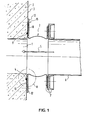
- the fireplace to be connected has a side inlet 1, which is lined with acid-resistant stones 2.
- the lining stones 2 also extend over the chimney part surrounding the inlet 1 and form an essentially flat surface 3. From this, a closed groove 4, which surrounds the inlet 1 at a distance of several centimeters, is worked out by milling or grinding.
- the groove 4 is advantageously provided by using already shaped casing stones 2, as will be explained in more detail later with reference to FIGS. 6 and 7.
- a compensator 7 made of rubber-elastic material is fastened at one end by an arrangement 7 'known per se, consisting of a flange, terminal strips and screw connections.
- the other end of the compensator 7 has a radially projecting flange 8 also made of rubber-elastic material, from which a bead 9 is integrally formed at a radial distance of several centimeters from the inner flange edge and protrudes from the front surface 10.
- the cross-sectional shape and arrangement of the bead 9 is selected according to the groove 4, i.e. there is a complementary shape, the cross section of the bead being equal to or slightly smaller than that of the groove 4.
- the front surface 10 of the flange 8 is glued to the flat surface 3 of the casing stones 2 and the bead 9 is glued to the groove 4 by means of a layer 11 (see FIGS. 2 and 3), which consists of a two-component elastomer adhesive, which in non-vulcanized state was applied as a plastic rubber composition and then crosslinked and assumes a rubber-elastic state.
- the layer looks coarser and finer Unevenness of the lining stones 2 and 4 formed in it groove and its thickness is dimensioned according to the largest occurring unevenness.
- the flange 8 is pressed against the flat surface 3 by a plurality of clamping parts 12. These consist of clamping strips 14 'which abut one another with little play, which engage over a large area on the rear side 13 of the flange 8 and cover the bead 9, including regions adjoining on both sides.
- the clamping strips 14 ' project radially outward beyond the flange 8 and have pressure pieces 14 ′′ in the region of their outer ends, which correspond approximately to the thickness of the flange 8 and are still supported on the flat surface 3 of the casing stones 2.
- the flange 8 and the pressure pieces 14 ′′ are provided with screw connections 15, each of which contains a first component anchored to the casing 3 (for example a stud bolt) and a second component (for example a nut) which is connected via a thread and causes a compressive force on the terminal strips 14 ′.
- the terminal strips 14 'and the pressure pieces 14 "are made of commercially available structural steel and are completely covered with a protective layer 16 of rubber-elastic material indicated as a thick solid line in FIG. 2.
- the bead 9 and thus also the groove 4 have a triangular cross-sectional shape.
- Modified embodiments according to FIGS. 2 and 3 have a bead 9' and a groove 4 'with a trapezoidal cross-section or a bead 9 "and a groove 4" with a semicircular cross-section.
- the groove 4 "' has an undercut 4 a and 4 b on each of its two side flanks.
- the bead 9"' has lateral projections. which are held positively in these undercuts 4 a and 4 b.
- the bead 9 "' also contains a hollow chamber 9a which extends parallel to its longitudinal axis and which facilitates its introduction into the groove 4"'.
- the clamping parts 12 consist of a plurality of flat rods 17 abutting one another with little play, each of which in turn is pressed on by a plurality of clamping claws 18 and screw connections 15.
- Both the flat bars 17 and the clamping claws 18 consist of commercially available structural steel and each have a closed protective layer 16 made of rubber-elastic material.
- the flat bars 17 can also be dispensed with and the pressing with the clamping claws 18 can be carried out alone.
- clamping parts 12 can also be used in the embodiments according to FIGS. 1-3, as conversely the clamping parts with clamping strips 14 ′ and pressure pieces 14 ′′ explained there can also be used in the case of FIGS. 4 and 5.
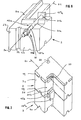
- the lining bricks 2 in their entirety form an inlet 1 (FIG. 1) of the chimney surrounding frame and comprise, inter alia, two joint surfaces 2a, to which adjacent lining bricks 2 adjacent to each other via joints 19, as well as a part of the wall of the inlet 1 side forming surface 2 b, a part of the flat surface 3 surrounding the inlet 1, to the joint surfaces 2 a perpendicular front surface 2 c and a parallel rear surface 2 d.
- the lining stones 2 can in a surface 2 a have a rib-like projection and on the other surface 2 a have a complementary recess and have an L-shaped shape parallel to the joint surfaces 2 a.
- Each casing 2 contains in its front surface 2 c and at a distance from the side surface 2 b a groove section 22 already provided in its manufacture, which extends from one of the surfaces 2 a to the other surface 2 a.
- the groove sections 22, which in their entirety form a closed groove 4 surrounding the inlet 1, can also have a different cross-sectional shape, as shown in FIGS. 1 and 3-5, deviating from the cross-sectional shape shown (corresponding to FIG. 2) is illustrated.
- the lining stones 2 have cutouts 20, the longitudinal axes 21 of which are perpendicular to the front surfaces 2c.
- Each recess 20 is formed half in relation to the longitudinal axis 21 in the joint surface 2a in such a way already during the production of the lining stone 2 that two lining stones 2 lying against one another on their joint surfaces 2a form a complete recess 20.
- Each recess 20 is composed of a deeper section 20 a starting from the front surface 2 c with a (based on the longitudinal axis 21) circular cross-sectional shape and an adjoining, axially flatter, but radially further second section 20 b together. The latter has the shape of a cuboid pocket open to the rear surface 2 d.
- the screw connection 15 contains a first component 15a, consisting of a cylindrical shaft 15'a carrying an external thread 15 "a at one end and an anchoring part 15" 'a fastened at the other end in the form of a rectangular plate welded in the middle.
- the second component 15 b consists of a nut screwed onto the thread 15 "a.
- the first components 15 a of the screw connection 15 are inserted in such a way that the anchoring parts 15 ′′ ′′ lie in the second sections 20 b of the cutouts 20 and are held against rotation, while the first sections 20 a with the threads 15 '' '' a project over the front surfaces 2 c.
- the cutouts 20 and / or the first components 15 a of the screw connections 15 arranged therein can also be present only in part of the casing stones can be provided or recesses that are not open to the joint surfaces 2 a can be provided exclusively or additionally.
Landscapes
- Engineering & Computer Science (AREA)
- Mechanical Engineering (AREA)
- General Engineering & Computer Science (AREA)
- Chimneys And Flues (AREA)
Priority Applications (1)
| Application Number | Priority Date | Filing Date | Title |
|---|---|---|---|
| AT85114003T ATE36397T1 (de) | 1984-11-05 | 1985-11-04 | Kaminanschluss fuer ein rauchgasrohr. |
Applications Claiming Priority (4)
| Application Number | Priority Date | Filing Date | Title |
|---|---|---|---|
| DE3440375A DE3440375A1 (de) | 1984-11-05 | 1984-11-05 | Kaminanschluss fuer ein rauchgasrohr |
| DE3440375 | 1984-11-05 | ||
| DE19848435025 DE8435025U1 (de) | 1984-11-29 | 1984-11-29 | Einrichtung zum anschluss eines rauchgasrohres an einen kamin |
| DE8435025U | 1984-11-29 |
Publications (2)
| Publication Number | Publication Date |
|---|---|
| EP0183090A1 true EP0183090A1 (fr) | 1986-06-04 |
| EP0183090B1 EP0183090B1 (fr) | 1988-08-10 |
Family
ID=25826256
Family Applications (1)
| Application Number | Title | Priority Date | Filing Date |
|---|---|---|---|
| EP85114003A Expired EP0183090B1 (fr) | 1984-11-05 | 1985-11-04 | Raccordement de cheminée pour un conduit de fumée |
Country Status (2)
| Country | Link |
|---|---|
| EP (1) | EP0183090B1 (fr) |
| DE (1) | DE3564332D1 (fr) |
Cited By (1)
| Publication number | Priority date | Publication date | Assignee | Title |
|---|---|---|---|---|
| WO2020104304A1 (fr) * | 2018-11-22 | 2020-05-28 | Henkel Ag & Co. Kgaa | Matériau d'étanchéité, module et utilisation d'un matériau d'étanchéité |
Citations (3)
| Publication number | Priority date | Publication date | Assignee | Title |
|---|---|---|---|---|
| GB1554397A (en) * | 1977-10-21 | 1979-10-17 | Skates R | Expansible coupling for duct sections |
| DE2847892A1 (de) * | 1978-11-04 | 1980-05-14 | Pforzheim Metallschlauch | Kompensator fuer rohrleitungen |
| DE2852856A1 (de) * | 1978-12-07 | 1980-06-19 | Continental Gummi Werke Ag | Schlauchkoerper, insbesondere zum ausgleichen von laengenaenderungen dienender balgfoermiger rohrverbinder |
Family Cites Families (1)
| Publication number | Priority date | Publication date | Assignee | Title |
|---|---|---|---|---|
| DE7116114U (fr) * | 1900-01-01 | Schulz K |
-
1985
- 1985-11-04 DE DE8585114003T patent/DE3564332D1/de not_active Expired
- 1985-11-04 EP EP85114003A patent/EP0183090B1/fr not_active Expired
Patent Citations (3)
| Publication number | Priority date | Publication date | Assignee | Title |
|---|---|---|---|---|
| GB1554397A (en) * | 1977-10-21 | 1979-10-17 | Skates R | Expansible coupling for duct sections |
| DE2847892A1 (de) * | 1978-11-04 | 1980-05-14 | Pforzheim Metallschlauch | Kompensator fuer rohrleitungen |
| DE2852856A1 (de) * | 1978-12-07 | 1980-06-19 | Continental Gummi Werke Ag | Schlauchkoerper, insbesondere zum ausgleichen von laengenaenderungen dienender balgfoermiger rohrverbinder |
Cited By (1)
| Publication number | Priority date | Publication date | Assignee | Title |
|---|---|---|---|---|
| WO2020104304A1 (fr) * | 2018-11-22 | 2020-05-28 | Henkel Ag & Co. Kgaa | Matériau d'étanchéité, module et utilisation d'un matériau d'étanchéité |
Also Published As
| Publication number | Publication date |
|---|---|
| EP0183090B1 (fr) | 1988-08-10 |
| DE3564332D1 (en) | 1988-09-15 |
Similar Documents
| Publication | Publication Date | Title |
|---|---|---|
| EP2176552B1 (fr) | Pompe à vis sans fin excentrique à stator segmenté | |
| DE69810362T2 (de) | Dichtverbindung zwischen Fluidbohrungen | |
| DE3237213C2 (fr) | ||
| DE2910090C2 (de) | Dichtungsstreifen zum Abdichten von Stoßfugen an Kreuzungsstellen zwischen einzelnen vorgefertigten Bauelementen | |
| DE102008021920A1 (de) | Exzenterschneckenpumpe | |
| DE19507854A1 (de) | Mehrteilige Dichtungsvorrichtung | |
| EP0372200B1 (fr) | Adaptateur d'injection ayant un élément de fixation et procédé pour l'application d'une inhibition de la corrosion | |
| EP1095206B1 (fr) | Dispositif d'etancheite | |
| WO1997048924A1 (fr) | Garniture d'etancheite | |
| DE3702477A1 (de) | Abdichtung an steckmuffenverbindungen von betonrohren | |
| EP0943803A1 (fr) | Stator pour pompe moineau | |
| EP0183090B1 (fr) | Raccordement de cheminée pour un conduit de fumée | |
| EP0348870B1 (fr) | Construction constituée par l'assemblage d'éléments préfabriqués en béton armé utilisant la technique du béton précontraint | |
| EP0611855A1 (fr) | Dispositif pour l'assemblage de deux sections de tubes internes céramiques d'une cheminée | |
| DE3440375C2 (fr) | ||
| DE19757751A1 (de) | Dichtungsvorrichtung zum abdichtenden Durchführen mindestens einer Leitung@ | |
| DE3008711A1 (de) | Gelenkige verbindung von tuebbingen | |
| DE3444141A1 (de) | Kompensator | |
| AT395342B (de) | Tunnelausbau aus vorgefertigten bauteilen | |
| EP1275809A2 (fr) | Cadre changeable pour fenêtres, portes ou façades métalliques | |
| DE3145924A1 (de) | Stossverbindung von bewehrungsstaeben | |
| DE9105302U1 (de) | Schalungszwinge | |
| DE4134208C2 (de) | Schneiddübel | |
| DE858344C (de) | Rohrverbindung mit Dichtungsstreifen aus Kautschuk | |
| DE3416334A1 (de) | Vorrichtung zur halterung einer glasscheibe eines fensters |
Legal Events
| Date | Code | Title | Description |
|---|---|---|---|
| PUAI | Public reference made under article 153(3) epc to a published international application that has entered the european phase |
Free format text: ORIGINAL CODE: 0009012 |
|
| AK | Designated contracting states |
Kind code of ref document: A1 Designated state(s): AT DE FR GB IT NL |
|
| 17P | Request for examination filed |
Effective date: 19861113 |
|
| 17Q | First examination report despatched |
Effective date: 19870827 |
|
| ITF | It: translation for a ep patent filed | ||
| GRAA | (expected) grant |
Free format text: ORIGINAL CODE: 0009210 |
|
| AK | Designated contracting states |
Kind code of ref document: B1 Designated state(s): AT DE FR GB IT NL |
|
| REF | Corresponds to: |
Ref document number: 36397 Country of ref document: AT Date of ref document: 19880815 Kind code of ref document: T |
|
| REF | Corresponds to: |
Ref document number: 3564332 Country of ref document: DE Date of ref document: 19880915 |
|
| ET | Fr: translation filed | ||
| GBT | Gb: translation of ep patent filed (gb section 77(6)(a)/1977) | ||
| PLBE | No opposition filed within time limit |
Free format text: ORIGINAL CODE: 0009261 |
|
| STAA | Information on the status of an ep patent application or granted ep patent |
Free format text: STATUS: NO OPPOSITION FILED WITHIN TIME LIMIT |
|
| 26N | No opposition filed | ||
| PGFP | Annual fee paid to national office [announced via postgrant information from national office to epo] |
Ref country code: FR Payment date: 19900926 Year of fee payment: 6 |
|
| PGFP | Annual fee paid to national office [announced via postgrant information from national office to epo] |
Ref country code: AT Payment date: 19901001 Year of fee payment: 6 |
|
| PGFP | Annual fee paid to national office [announced via postgrant information from national office to epo] |
Ref country code: NL Payment date: 19901130 Year of fee payment: 6 |
|
| PG25 | Lapsed in a contracting state [announced via postgrant information from national office to epo] |
Ref country code: AT Effective date: 19911104 |
|
| ITTA | It: last paid annual fee | ||
| PG25 | Lapsed in a contracting state [announced via postgrant information from national office to epo] |
Ref country code: NL Effective date: 19920601 |
|
| NLV4 | Nl: lapsed or anulled due to non-payment of the annual fee | ||
| PG25 | Lapsed in a contracting state [announced via postgrant information from national office to epo] |
Ref country code: FR Effective date: 19920731 |
|
| REG | Reference to a national code |
Ref country code: FR Ref legal event code: ST |
|
| PGFP | Annual fee paid to national office [announced via postgrant information from national office to epo] |
Ref country code: GB Payment date: 19941101 Year of fee payment: 10 |
|
| PG25 | Lapsed in a contracting state [announced via postgrant information from national office to epo] |
Ref country code: GB Effective date: 19951104 |
|
| GBPC | Gb: european patent ceased through non-payment of renewal fee |
Effective date: 19951104 |
|
| PGFP | Annual fee paid to national office [announced via postgrant information from national office to epo] |
Ref country code: DE Payment date: 19990129 Year of fee payment: 14 |
|
| PG25 | Lapsed in a contracting state [announced via postgrant information from national office to epo] |
Ref country code: DE Free format text: LAPSE BECAUSE OF NON-PAYMENT OF DUE FEES Effective date: 20000901 |