EP0183101A1 - Installation à énergie nucléaire à refroidissement par métal liquide avec générateurs de vapeur intégrés dans l'enceinte de sécurité - Google Patents
Installation à énergie nucléaire à refroidissement par métal liquide avec générateurs de vapeur intégrés dans l'enceinte de sécurité Download PDFInfo
- Publication number
- EP0183101A1 EP0183101A1 EP85114151A EP85114151A EP0183101A1 EP 0183101 A1 EP0183101 A1 EP 0183101A1 EP 85114151 A EP85114151 A EP 85114151A EP 85114151 A EP85114151 A EP 85114151A EP 0183101 A1 EP0183101 A1 EP 0183101A1
- Authority
- EP
- European Patent Office
- Prior art keywords
- cells
- safety enclosure
- coolant
- steam generators
- cooled nuclear
- Prior art date
- Legal status (The legal status is an assumption and is not a legal conclusion. Google has not performed a legal analysis and makes no representation as to the accuracy of the status listed.)
- Withdrawn
Links
- 238000009434 installation Methods 0.000 title description 2
- 239000007788 liquid Substances 0.000 title 1
- 239000002826 coolant Substances 0.000 claims abstract description 9
- 238000001816 cooling Methods 0.000 claims description 3
- 230000007257 malfunction Effects 0.000 claims 1
- 238000010438 heat treatment Methods 0.000 abstract description 2
- 238000009413 insulation Methods 0.000 abstract description 2
- XLYOFNOQVPJJNP-UHFFFAOYSA-N water Substances O XLYOFNOQVPJJNP-UHFFFAOYSA-N 0.000 description 4
- DGAQECJNVWCQMB-PUAWFVPOSA-M Ilexoside XXIX Chemical compound C[C@@H]1CC[C@@]2(CC[C@@]3(C(=CC[C@H]4[C@]3(CC[C@@H]5[C@@]4(CC[C@@H](C5(C)C)OS(=O)(=O)[O-])C)C)[C@@H]2[C@]1(C)O)C)C(=O)O[C@H]6[C@@H]([C@H]([C@@H]([C@H](O6)CO)O)O)O.[Na+] DGAQECJNVWCQMB-PUAWFVPOSA-M 0.000 description 3
- 229910052708 sodium Inorganic materials 0.000 description 3
- 239000011734 sodium Substances 0.000 description 3
- 238000010276 construction Methods 0.000 description 2
- 229910000528 Na alloy Inorganic materials 0.000 description 1
- 238000007664 blowing Methods 0.000 description 1
- 238000009835 boiling Methods 0.000 description 1
- 230000005494 condensation Effects 0.000 description 1
- 238000009833 condensation Methods 0.000 description 1
- 230000000694 effects Effects 0.000 description 1
- 238000007689 inspection Methods 0.000 description 1
- 230000014759 maintenance of location Effects 0.000 description 1
- 229910052751 metal Inorganic materials 0.000 description 1
- 239000002184 metal Substances 0.000 description 1
- 230000002285 radioactive effect Effects 0.000 description 1
- 239000000126 substance Substances 0.000 description 1
Images

Classifications
-
- G—PHYSICS
- G21—NUCLEAR PHYSICS; NUCLEAR ENGINEERING
- G21C—NUCLEAR REACTORS
- G21C1/00—Reactor types
- G21C1/02—Fast fission reactors, i.e. reactors not using a moderator ; Metal cooled reactors; Fast breeders
-
- Y—GENERAL TAGGING OF NEW TECHNOLOGICAL DEVELOPMENTS; GENERAL TAGGING OF CROSS-SECTIONAL TECHNOLOGIES SPANNING OVER SEVERAL SECTIONS OF THE IPC; TECHNICAL SUBJECTS COVERED BY FORMER USPC CROSS-REFERENCE ART COLLECTIONS [XRACs] AND DIGESTS
- Y02—TECHNOLOGIES OR APPLICATIONS FOR MITIGATION OR ADAPTATION AGAINST CLIMATE CHANGE
- Y02E—REDUCTION OF GREENHOUSE GAS [GHG] EMISSIONS, RELATED TO ENERGY GENERATION, TRANSMISSION OR DISTRIBUTION
- Y02E30/00—Energy generation of nuclear origin
- Y02E30/30—Nuclear fission reactors
Definitions
- the present invention relates to a nuclear power plant according to the preamble of claim 1.
- the scheme of such a nuclear power plant is e.g. B. from DE-A-24 45 553 known.
- Sodium or a sodium alloy is preferably used as the primary and secondary coolant, while water is used as the tertiary coolant, which is evaporated in the heat exchangers which transmit the heat from the secondary to the tertiary cooling circuit and is then used as a working medium for operating power generators.
- the steam represents a significant pressure energy potential that z. B. due to a larger steam generator leak to the eventual condensation leads to a considerable load on the enclosing building.
- the safety containment of the reactor building need not be designed against high internal pressure loads and its ability to possibly remove the radioactivity contained in the reactor itself and in the primary circuit Safe retention is guaranteed even without the complex installation of a tight sheet metal lining.
- the reactor building should be able to provide sufficient resistance to external influences, in particular an aircraft crash. This leads to reactor buildings of cylindrical and / or hemispherical shape, which in turn require that the steam generator buildings can only be arranged at a certain distance therefrom.
- the pipes forming the secondary circuit become relatively long, which has a number of disadvantages: higher pressure loss - higher heat loss despite extensive insulation - more complex trace heating - larger number of pipe loops to compensate for the impeded thermal expansion - larger number of welds subject to inspection - larger coolant volume, which in turn forces drain containers etc. to be enlarged accordingly, as well as an increase in the construction volume required to accommodate the system.
- the object of the present invention is to arrange the various components belonging to the cooling circuit of such a nuclear power plant in such a way that the above-mentioned. Disadvantages are avoided or minimized.
- Non-radioactive parts of the plant that contain high-tension water or steam ie the steam generator with the necessary connection lines can therefore be arranged within the safety enclosure of the reactor building, because the cells surrounding them can withstand a pressure build-up taking place in them at any time, so that the former does not have any particular pressure loads must withstand inside; in a preferred embodiment defined by the second claim, in that possibilities for pressure relief from the cells are created through the safety enclosure into the atmosphere.
- the individual components of the heat transfer circuits can then be arranged in the immediate vicinity of one another, which, as explained above, subsequently leads to considerable savings in plant costs.
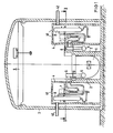
- a reactor tank 1 which is surrounded by a biological shield 2, is common to both types of plant.
- the entire primary circuit including a pump 5 circulating the primary coolant is arranged within the reactor tank 1, as are intermediate heat exchangers 6, in which the primary circuit gives off its heat to the secondary circuit, which is also operated with sodium.
- the primary pump 5 and the intermediate heat exchanger 6 are arranged outside the reactor tank 1.
- the secondary circuit is maintained by further pumps 7 and closes steam generator 8 .
- a in which water vapor is generated on the tertiary side, which is supplied to machines not shown here, preferably turbogenerators.
- the above-mentioned system parts are arranged within a safety enclosure 3 made of concrete, which can withstand both external influences, such as an aircraft crash, and any internal activity releases that could be caused by possible leaks.
- Secondary pumps 7 and steam generator 8 and the associated pipelines that is to say those parts of the plant which, in the event of accidents, could result in considerable energy releases are arranged in special cells 4 which are independent of the safety enclosure 3 and which are suitable in terms of their construction, such energy Resist releases in their interior, preferably in that they are provided with relief channels 42 which led through the wall of the safety enclosure 3 into the open and in normal operation z. B. ' are closed with rupture discs, not shown here.
- the cells 4 are provided on their upper side with openings 41 which are closed with corresponding plugs during operation.
Landscapes
- Physics & Mathematics (AREA)
- Engineering & Computer Science (AREA)
- Plasma & Fusion (AREA)
- General Engineering & Computer Science (AREA)
- High Energy & Nuclear Physics (AREA)
- Structure Of Emergency Protection For Nuclear Reactors (AREA)
Applications Claiming Priority (2)
| Application Number | Priority Date | Filing Date | Title |
|---|---|---|---|
| DE3442236 | 1984-11-19 | ||
| DE19843442236 DE3442236A1 (de) | 1984-11-19 | 1984-11-19 | Fluessigmetallgekuehlte kernenergieanlage mit in den sicherheitseinschluss integrierten dampferzeugern |
Publications (1)
| Publication Number | Publication Date |
|---|---|
| EP0183101A1 true EP0183101A1 (fr) | 1986-06-04 |
Family
ID=6250664
Family Applications (1)
| Application Number | Title | Priority Date | Filing Date |
|---|---|---|---|
| EP85114151A Withdrawn EP0183101A1 (fr) | 1984-11-19 | 1985-11-06 | Installation à énergie nucléaire à refroidissement par métal liquide avec générateurs de vapeur intégrés dans l'enceinte de sécurité |
Country Status (2)
| Country | Link |
|---|---|
| EP (1) | EP0183101A1 (fr) |
| DE (1) | DE3442236A1 (fr) |
Families Citing this family (3)
| Publication number | Priority date | Publication date | Assignee | Title |
|---|---|---|---|---|
| RU2188472C2 (ru) * | 2000-11-08 | 2002-08-27 | Опытное Конструкторское Бюро "Гидропресс" | Способ передачи тепловой энергии источника рабочему телу энергетической установки посредством жидкометаллического теплоносителя |
| RU2212066C1 (ru) * | 2002-05-17 | 2003-09-10 | Фгуп Окб "Гидропресс" | Ядерный паропроизводящий агрегат с жидкометаллическим теплоносителем |
| RU2762391C1 (ru) * | 2021-06-27 | 2021-12-20 | Виталий Алексеевич Узиков | Реакторная установка на быстрых нейтронах с пассивной системой охлаждения активной зоны |
Citations (1)
| Publication number | Priority date | Publication date | Assignee | Title |
|---|---|---|---|---|
| FR2246028A1 (fr) * | 1973-10-02 | 1975-04-25 | Electricite De France |
-
1984
- 1984-11-19 DE DE19843442236 patent/DE3442236A1/de not_active Withdrawn
-
1985
- 1985-11-06 EP EP85114151A patent/EP0183101A1/fr not_active Withdrawn
Patent Citations (1)
| Publication number | Priority date | Publication date | Assignee | Title |
|---|---|---|---|---|
| FR2246028A1 (fr) * | 1973-10-02 | 1975-04-25 | Electricite De France |
Non-Patent Citations (1)
| Title |
|---|
| CONFERENCE SUR LA SURETE DES REACTEURS RAPIDES, 19.-23. Juli 1982, Lyon, FR; C. AYCOBERRY et al.: "L'après CREYS-MALVILLE: Les perspectives du projet de site intégré" * |
Also Published As
| Publication number | Publication date |
|---|---|
| DE3442236A1 (de) | 1986-05-22 |
Similar Documents
| Publication | Publication Date | Title |
|---|---|---|
| DE3435255C2 (fr) | ||
| DE1097048B (de) | Kernreaktoranlage mit Druckbehaelter | |
| DE2220486C3 (de) | Druckwasserreaktor | |
| CH670011A5 (fr) | ||
| EP0039016A1 (fr) | Réacteur nucléaire à haute température en ensemble modulaire | |
| CH690877A5 (de) | Siedewasserreaktor mit einem Sicherheitsbehälter mit unterteiltem Flutbeckenraum. | |
| CH672965A5 (fr) | ||
| DE3742876A1 (de) | Verfahren und anordnung zur erneuerung eines senkrecht angeordneten dampferzeugers, insbesondere in kernkraftwerken | |
| DE2812124A1 (de) | Kernenergieanlage in loop-anordnung | |
| DE1464490A1 (de) | Waermetauscher,insbesondere fuer Kernreaktoren | |
| CH689240A5 (de) | Kernrohr- und Tragplattenbaueinheit fuer Druckwasserkernreaktor. | |
| DE1576867B2 (de) | Im Kuhlmittelstrom eines Kernreaktors angeordneter Dampferzeuger | |
| EP0183101A1 (fr) | Installation à énergie nucléaire à refroidissement par métal liquide avec générateurs de vapeur intégrés dans l'enceinte de sécurité | |
| DE2621258A1 (de) | Kernenergieanlage mit verbesserten einrichtungen zur nach- und notwaermeabfuhr | |
| DE69807195T2 (de) | Kernkraftwerk | |
| DE1564162A1 (de) | Vorrichtung zum Abziehen der Waerme aus einem Kernreaktor | |
| DE2618345A1 (de) | Austrittsstutzen- und eintrittsleitungs-kombination fuer einen kernreaktor- druckbehaelter | |
| DE2133410C3 (de) | Wärmeaustauscher für einen Reaktor mit Natriumkuhlung | |
| DE3425144C2 (fr) | ||
| DE2234573A1 (de) | Kerndampferzeuger | |
| DE3518174A1 (de) | Waermeabfuhrsystem zum abfuehren von nachwaerme aus der primaerzelle eines hochtemperaturreaktors | |
| DE1083944B (de) | Vorrichtung zum Einbringen eines Bauteils oder einer Bauteilgruppe in einen Stroemungsmittelkreislauf, insbesondere fuer Kernreaktoren | |
| DE1464849B1 (de) | Atomkernreaktoranlage | |
| DE2046548A1 (de) | Wärmetauscher fur natnumgekuhlte Kernreaktoren | |
| EP0143229B1 (fr) | Installation nucléaire avec une protection simplifiée contre les fuites des circuits de refroidissement |
Legal Events
| Date | Code | Title | Description |
|---|---|---|---|
| PUAI | Public reference made under article 153(3) epc to a published international application that has entered the european phase |
Free format text: ORIGINAL CODE: 0009012 |
|
| AK | Designated contracting states |
Kind code of ref document: A1 Designated state(s): BE DE FR GB IT NL |
|
| 17P | Request for examination filed |
Effective date: 19860707 |
|
| 17Q | First examination report despatched |
Effective date: 19880118 |
|
| STAA | Information on the status of an ep patent application or granted ep patent |
Free format text: STATUS: THE APPLICATION IS DEEMED TO BE WITHDRAWN |
|
| 18D | Application deemed to be withdrawn |
Effective date: 19890531 |
|
| RIN1 | Information on inventor provided before grant (corrected) |
Inventor name: HAHN, GUENTER, DIPL.-ING. |