EP0183268A2 - Auflage für den Bedienhörer eines Autotelefons - Google Patents
Auflage für den Bedienhörer eines Autotelefons Download PDFInfo
- Publication number
- EP0183268A2 EP0183268A2 EP85115105A EP85115105A EP0183268A2 EP 0183268 A2 EP0183268 A2 EP 0183268A2 EP 85115105 A EP85115105 A EP 85115105A EP 85115105 A EP85115105 A EP 85115105A EP 0183268 A2 EP0183268 A2 EP 0183268A2
- Authority
- EP
- European Patent Office
- Prior art keywords
- handset
- shaped
- edition according
- support
- edition
- Prior art date
- Legal status (The legal status is an assumption and is not a legal conclusion. Google has not performed a legal analysis and makes no representation as to the accuracy of the status listed.)
- Granted
Links
Images
Classifications
-
- H—ELECTRICITY
- H04—ELECTRIC COMMUNICATION TECHNIQUE
- H04M—TELEPHONIC COMMUNICATION
- H04M1/00—Substation equipment, e.g. for use by subscribers
- H04M1/02—Constructional features of telephone sets
- H04M1/04—Supports for telephone transmitters or receivers
- H04M1/06—Hooks; Cradles
-
- H—ELECTRICITY
- H04—ELECTRIC COMMUNICATION TECHNIQUE
- H04M—TELEPHONIC COMMUNICATION
- H04M1/00—Substation equipment, e.g. for use by subscribers
- H04M1/02—Constructional features of telephone sets
- H04M1/04—Supports for telephone transmitters or receivers
-
- H—ELECTRICITY
- H04—ELECTRIC COMMUNICATION TECHNIQUE
- H04M—TELEPHONIC COMMUNICATION
- H04M1/00—Substation equipment, e.g. for use by subscribers
- H04M1/02—Constructional features of telephone sets
- H04M1/04—Supports for telephone transmitters or receivers
- H04M1/06—Hooks; Cradles
- H04M1/10—Hooks; Cradles associated with switches operated by magnetic effect due to proximity of receiver or hand-set
Definitions
- the invention relates to a requirement for the handset of a car phone.
- car telephones consisted of an operating unit with a display and dialing device and a separate handset.
- the control unit was either in a corresponding cutout in the dashboard or in a special console in the passenger compartment.
- the headset also required a pad that significantly exceeded its dimensions. When the headset was removed or replaced, a mechanical contact, the so-called fork switch, was opened or closed.
- the hook switch was designed so that it fixed the headset in place using spring-loaded latches.
- the invention has for its object to provide a simple, space-saving support for an operating handset in its construction, which at the same time contains all the display and selection devices of an otherwise customary separate operating device.
- a support consisting of a plate-shaped lower part and a cap-shaped upper part which can be placed thereon and which has a correspondingly shaped depression in its area provided for receiving the part of the handset containing the earpiece and in its raised area with two slit-shaped recesses and an underlying pot-shaped shape is provided, in which two holding plates with magnets in between are arranged so that they protrude through the two slots on the top of the support and hold a steel plate inserted in the handset and thus the handset itself in its position due to the magnetic action .
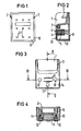
- Figures 1 to 4 show the support in a bottom view, a section in the longitudinal direction, a plan view and a section in the transverse direction.
- the support for the handset which contains all display and selection devices, has a cuboid shape and consists of a plate-shaped lower part 8 and a cap-shaped upper part 10 surrounding lower part 8 at the edge.
- Lower part 8 and upper part 10 are via screws 11 connected to each other, which are inserted in depressions of the upper part 10 and engage in sleeve-shaped projections 15 on the inside of the lower part 8.
- the edition is designed so that it only corresponds to about a third of the size of the handset.
- the upper part of the upper part 10 has a recess 1 which is matched to the earpiece part of the handset.
- existing wedges 2 are arranged in vertically extending slots 3 of the upper part 10 of the support made of soft material, preferably plastic. This compensates for any lateral play between the handset and the support.
- the lower, raised part 14 of the cap-shaped upper part 10 is provided with two parallel slot-shaped recesses 6 and a cup-shaped shape underneath.
- two holding plates 4 with an interposed magnet 5 are arranged from the underside in such a way that they protrude through the two slots 6 on the upper side of the support and hold a steel plate inserted into the handset and thus hold the handset itself in place by the magnetic effect.
- the holding plates 4 are arranged movably to compensate for tolerances in the support and thus enable a flat contact of the top of the holding plates with the steel plate inserted in the handset.
- the function of the fork switch is achieved in that an additional magnet 7, preferably a round magnet, inserted in a cavity of the upper part 10 actuates a reed relay arranged in a corresponding position in the handset, which thus, among other things. enables the call to be set up.
- this round magnet 7, via a second reed relay arranged in the handset when the handset is lifted, regulates the maximum volume of an incoming call signal when it is on-hook so that no painful stimuli arise for the user during a conversation.
- the plate-shaped lower part 8 has a number of bores 9, via which the support is fastened to a mounting surface in the vehicle by means of screws. After the lower part 8 has been fastened to the fastening surface, the lower part 8 is screwed to the upper part 10 of the support. The depressions for receiving the two screws 11 in the upper part 10 are then closed by two cover caps 12 which project over the top of the support.
- a third, as well as the cover caps 12 made of soft material, which protrudes somewhat from the top of the support, fulfills the purpose with the other two cover caps 12 to form a counter bearing to the two likewise protruding magnetic holding plates in order to rattle during to avoid driving.
Landscapes
- Engineering & Computer Science (AREA)
- Signal Processing (AREA)
- Telephone Set Structure (AREA)
- Fittings On The Vehicle Exterior For Carrying Loads, And Devices For Holding Or Mounting Articles (AREA)
- Telephone Function (AREA)
Abstract
Description
- Die Erfindung bezieht sich auf eine Auflage für den Bedienhörer eines Autotelefons.
- Die Ausrüstung von Fahrzeugen mit Kommunikationsmitteln, insbesondere mit Autotelefonen, macht es erforderlich, das im Fahrzeug sehr geringe Platzangebot so zu nutzen, daß die notwendigen Geräte zur Kommunikation so klein wie möglich werden. Dies geschieht durch einen mit Anzeige-und Wahlelementen versehenen Bedienhörer und eine dazu passende Halterung.
- Bei bisherigen Ausführungsformen bestanden Autotelefone aus einer Bedieneinheit mit Anzeige- und Wahleinrichtung und einem separaten Sprechhörer. Die Bedieneinheit war entweder in einem entsprechenden Ausschnitt im Armaturenbrett oder in einer besonderen Konsole im Fahrgastraum untergebracht. Der Sprechhörer benötigte zusätzlich eine Auflage, die dessen Maße erheblich überschritt. Beim Abnehmen oder Auflegen des Sprechhörers wurde ein mechanischer Kontakt, der sog. Gabelumschalter geöffnet oder geschlossen. Der Gabelumschalter war.dabei so ausgebildet, daß er den Sprechhörer über federnde Rasthalterungen in seiner Lage fixierte.
- Der Erfindung liegt die Aufgabe zugrunde, eine in ihrem Aufbau einfache, platzsparende Auflage für einen Bedienhörer zu schaffen, der zugleich alle Anzeige- und Wahleinrichtungen eines ansonsten üblichen separaten Bediengerätes mit enthält.
- Diese Aufgabe wird gemäß der Erfindung gelöst durch eine Auflage, bestehend aus einem plattenförmigen Unterteil und einem auf dieses aufsetzbaren kappenförmigen Oberteil, das in seinem für die Aufnahme des die Hörmuschel enthaltenden Teiles des Bedienhörers vorgesehenen Bereich eine entsprechend ausgeformte Vertiefung aufweist und in seinem erhöhten Bereich mit zwei schlitzförmigen Ausnehmungen und einer darunterliegenden topfförmigen Ausformung versehen ist, in der zwei Haltebleche mit dazwischenliegendem Magneten so angeordnet sind, daß sie durch die beiden Schlitze der Auflagenoberseite hindurchragen und durch die Xagnetwirkung eine in den Bedienhörer eingelegte Stahlplatte und damit den Bedienhörer selbst in seiner Lage festhalten.
- Vorteilhafte Ausgestaltungen und Weiterbildungen des Erfindungsgegenstandes sind in den Unteransprüchen angegeben.
- Nachstehend wird die Erfindung anhand eines in der Zeichnung dargestellten Ausführungsbeispiels näher erläutert.
- Die Figuren 1 bis 4 zeigen die Auflage in einer Unteransicht, einem Schnitt in Längsrichtung, einer Draufsicht und einem Schnitt in Querrichtung.
- Die Auflage für den in der Zeichnung nicht dargestellten Bedienhörer, der alle Anzeige- und Wahleinrichtungen enthält, hat quaderförmige Gestalt und besteht aus einem plattenförmigen Unterteil 8 und einem kappenförmigen, das Unterteil 8 am Rand umschließenden Oberteil 10. Unterteil 8 und Oberteil 10 sind über Schrauben 11 miteinander verbunden, die in Vertiefungen des Oberteils 10 eingesetzt sind und in hülsenförmige Ansätze 15 an der Innenseite des Unterteiles 8 eingreifen.
- Die Auflage ist so gestaltet, daß sie lediglich etwa einem Drittel der Größe des Bedienhörers entspricht. Für die Aufnahme und Halterung des Bedienhörers weist der obere Teil des Oberteils 10 eine Vertiefung 1 auf, die dem Hörmuschelteil des Bedienhörers angeglichen ist. Im Bereich der seitlichen Anlage des Bedienhörers innerhalb der Vertiefung 1 sind in senkrecht verlaufenden Schlitzen 3 des Oberteils 10 der Auflage aus weichem Material, vorzugsweise Kunststoff, bestehende Keile 2 angeordnet. Dadurch wird ein seitliches Spiel zwischen Bedienhörer und Auflage ausgeglichen.
- Der untere, erhöhte Teil 14 des kappenförmigen Oberteils 10 ist mit zwei parallel verlaufenden schlitzförmigen Ausnehmungen 6 und einer darunterliegenden topfförmigen Ausformung versehen. In diese Ausformung werden von der Unterseite her zwei Haltebleche 4 mit einem dazwischenliegenden Magneten 5 so angeordnet, daß sie durch die beiden Schlitze.6 der Auflagenoberseite hindurchragen und durch die Magnetwirkung eine in den Bedienhörer eingelegte Stahlplatte und damit den Bedienhörer selbst in seiner Lage festhalten.
- Die Haltebleche 4 sind dabei zum Toleranzausgleich in der Auflage beweglich angeordnet und ermöglichen so eine flächige Anlage der Oberseite der Haltebleche an die im Bedienhörer eingelegte Stahlplatte. Die Funktion des Gabelumschalters wird dadurch erreicht, daß ein in einen Hohlraum des Oberteils 10 eingelegter zusätzlicher Magnet 7, vorzugsweise ein Rundmagnet, ein im Bedienhörer in entsprechender Lage angeordnetes Reedrelais betätigt, das damit u.a. den Gesprächsaufbau ermöglicht. Zusätzlich wird durch diesen Rundmagneten 7 über ein im Bedienhörer angeordnetes zweites Reedrelais beim Abheben des Hörers die im aufgelegten Zustand maximale Lautstärke eines ankommenden Rufsignals so geregelt, daß keine schmerzhaften Reize für den Benutzer beim Gespräch entstehen.
- Das plattenförmige Unterteil 8 weist eine Reihe von Bohrungen 9 auf, über die die Auflage mittels Schrauben an einer Montagefläche im Fahrzeug befestigt wird. Nach der Befestigung des Unterteils 8 an der Befestigungsfläche erfolgt die Verschraubung des Unterteils 8 mit dem Oberteil 10 der Auflage. Die Vertiefungen zur Aufnahme der beiden Schrauben 11 in dem Oberteil 10 werden anschließend durch zwei, über die Auflagenoberseite hervorragende Abdeckkappen 12 verschlossen. Eine dritte, ebenso wie die Abdeckkappen 12 aus weichem Material hergestellte Abdeckkappe 13, die etwas aus der Auflagenob.erseite hervorsteht, erfüllt dabei mit den beiden anderen Abdeckkappen 12 den Zweck, ein Gegenlager zu den beiden ebenfalls vorstehenden Magnethalteblechen zu bilden, um ein Klappern während der Fahrt zu vermeiden.
Claims (10)
dadurch gekennzeichnet , daß die Haltebleche (4) in der Auflage beweglich angeordnet sind.
dadurch gekennzeichnet ,
daß im Bereich der seitlichen Anlage des Bedienhörers innerhalb der Vertiefung (1) in senkrecht verlaufenden Schlitzen (3) des Oberteils (10) der Auflage eingesetzte Keile (2) aus weichem Material, vorzugsweise Kunststoff, angeordnet sind.
dadurch gekennzeichnet,
daß das Unterteil (8) der Auflage an der dem Oberteil (10) zugekehrten Fläche mit hülsenförmigen Ansätzen (15) versehen ist, in die das Oberteil (10) mit dem Unterteil (8) verbindende Schrauben (11) eingreifen.
dadurch gekennzeichnet,
daß Öffnungen im Oberteil (10) zur Aufnahme der Schrauben (11) mit die Oberfläche überragenden Abdeckkappen (12) verschlossen sind.
dadurch gekennzeichnet ,
daß zusätzlich eine weitere, aus der Oberteiloberseite hervorstehende Abdeckkappe (13) vorgesehen ist.
dadurch gekennzeichnet ,
daß die Abdeckkappen (12,13) aus einem weichen Material bestehen.
dadurch gekennzeichnet ,
daß im Innenraum des Oberteils (10) ein weiterer Magnet (7) angeordnet ist, der ein im Bedienhörer in entsprechender Lage angeordnetes Reedrelais betätigt.
dadurch gekennzeichnet ,
daß die Befestigung im Fahrzeug durch Verschraubung des Unterteils (8) an einer Befestigungsfläche erfolgt.
dadurch gekennzeichnet,
daß ihre Längenausdehnung etwa einem Drittel der Länge des Bedienhörers entspricht sowie dessen Breite nicht übersteigt.
Applications Claiming Priority (2)
| Application Number | Priority Date | Filing Date | Title |
|---|---|---|---|
| DE3443645 | 1984-11-29 | ||
| DE3443645 | 1984-11-29 |
Publications (3)
| Publication Number | Publication Date |
|---|---|
| EP0183268A2 true EP0183268A2 (de) | 1986-06-04 |
| EP0183268A3 EP0183268A3 (en) | 1987-09-02 |
| EP0183268B1 EP0183268B1 (de) | 1991-11-06 |
Family
ID=6251524
Family Applications (1)
| Application Number | Title | Priority Date | Filing Date |
|---|---|---|---|
| EP85115105A Expired - Lifetime EP0183268B1 (de) | 1984-11-29 | 1985-11-28 | Auflage für den Bedienhörer eines Autotelefons |
Country Status (7)
| Country | Link |
|---|---|
| US (1) | US4747136A (de) |
| EP (1) | EP0183268B1 (de) |
| DE (2) | DE8435049U1 (de) |
| DK (1) | DK550985A (de) |
| FI (1) | FI80178C (de) |
| NO (1) | NO164749C (de) |
| ZA (1) | ZA859108B (de) |
Cited By (1)
| Publication number | Priority date | Publication date | Assignee | Title |
|---|---|---|---|---|
| EP0526715A1 (de) * | 1991-06-27 | 1993-02-10 | Robert Bosch Gmbh | Auflage für einen Fernsprechhandapparat |
Families Citing this family (6)
| Publication number | Priority date | Publication date | Assignee | Title |
|---|---|---|---|---|
| US5128994A (en) * | 1990-03-15 | 1992-07-07 | Mitsubishi Denki Kabushiki Kaisha | Telephone handset with magnetic holder |
| US5109411A (en) * | 1990-06-21 | 1992-04-28 | Scientific Dimensions | Telephone handset cradle mount |
| US5060260A (en) * | 1990-07-24 | 1991-10-22 | Connell Joseph J O | Mounting cradle for a portable cellular telephone |
| JPH07203012A (ja) * | 1993-12-28 | 1995-08-04 | Hashimoto Corp | 留守番機能を有する自動車電話用付属装置。 |
| US5588055A (en) * | 1995-01-27 | 1996-12-24 | Williamson; Robert | Telephone holder with mounting assembly |
| WO2004100505A1 (en) * | 2003-05-09 | 2004-11-18 | Miikka Valkonen | Device for facilitating vehicular use of a mobile phone |
Family Cites Families (9)
| Publication number | Priority date | Publication date | Assignee | Title |
|---|---|---|---|---|
| US2623128A (en) * | 1946-03-15 | 1952-12-23 | Automatic Telephone & Elect | Telephone instrument with magnetic handset latch |
| DE849118C (de) * | 1951-04-12 | 1952-09-11 | Hermann Dipl-Ing Dr Tiefenbach | Fernsprechapparat |
| DE1214735B (de) * | 1964-04-23 | 1966-04-21 | Siemens Ag | Umschalter fuer Fernsprechstationen |
| GB1144485A (en) * | 1966-05-10 | 1969-03-05 | Ass Elect Ind | Improvements relating to telephone instruments |
| DE2009599A1 (de) * | 1970-03-02 | 1971-09-16 | Tekade Felten & Guilleaume | Unfallsicheres Fernsprechteilnehmer gerat, insbesondere fur Fahrzeuganlagen |
| IT983689B (it) * | 1973-04-06 | 1974-11-11 | Carava C | Citofono con cornetta scatola d aggancio e interruttore autto matico del circuito fonico |
| US4472606A (en) * | 1982-07-22 | 1984-09-18 | Motorola Inc. | Mobile radio-telephone handset and holder |
| US4581490A (en) * | 1983-12-22 | 1986-04-08 | Richard Genender | Wall telephone assembly |
| US4609785A (en) * | 1985-04-29 | 1986-09-02 | General Electric Company | Universal handset mount |
-
1984
- 1984-11-29 DE DE8435049U patent/DE8435049U1/de not_active Expired
-
1985
- 1985-11-15 US US06/798,307 patent/US4747136A/en not_active Expired - Fee Related
- 1985-11-25 NO NO854707A patent/NO164749C/no unknown
- 1985-11-28 DK DK550985A patent/DK550985A/da not_active Application Discontinuation
- 1985-11-28 EP EP85115105A patent/EP0183268B1/de not_active Expired - Lifetime
- 1985-11-28 FI FI854713A patent/FI80178C/fi not_active IP Right Cessation
- 1985-11-28 ZA ZA859108A patent/ZA859108B/xx unknown
- 1985-11-28 DE DE8585115105T patent/DE3584611D1/de not_active Expired - Lifetime
Cited By (1)
| Publication number | Priority date | Publication date | Assignee | Title |
|---|---|---|---|---|
| EP0526715A1 (de) * | 1991-06-27 | 1993-02-10 | Robert Bosch Gmbh | Auflage für einen Fernsprechhandapparat |
Also Published As
| Publication number | Publication date |
|---|---|
| DE3584611D1 (de) | 1991-12-12 |
| DE8435049U1 (de) | 1986-05-22 |
| EP0183268B1 (de) | 1991-11-06 |
| DK550985D0 (da) | 1985-11-28 |
| EP0183268A3 (en) | 1987-09-02 |
| US4747136A (en) | 1988-05-24 |
| FI80178C (fi) | 1990-04-10 |
| ZA859108B (en) | 1986-07-30 |
| FI854713A0 (fi) | 1985-11-28 |
| NO854707L (no) | 1986-05-30 |
| FI80178B (fi) | 1989-12-29 |
| NO164749B (no) | 1990-07-30 |
| FI854713L (fi) | 1986-05-30 |
| DK550985A (da) | 1986-05-30 |
| NO164749C (no) | 1990-11-07 |
Similar Documents
| Publication | Publication Date | Title |
|---|---|---|
| DE69029440T2 (de) | Tragbares Funktelefon | |
| EP1134108B1 (de) | Modulare Instrumententafel eines Kraftfahrzeuges | |
| EP0121927B1 (de) | Bedienteil für ein Autotelefon | |
| EP0183268A2 (de) | Auflage für den Bedienhörer eines Autotelefons | |
| DE19850044C2 (de) | Mobiltelefon-Halterung für ein Fahrzeug | |
| DE29623336U1 (de) | Handfunktelefon | |
| DE19538249A1 (de) | Halterungsvorrichtung für ein Funktelefon in einem Fahrzeug | |
| EP0822693B1 (de) | Freisprecheinrichtung für Telefone in Kraftfahrzeugen | |
| DE69129380T2 (de) | Aufnahmevorrichtung für ein tragbares Telefon | |
| EP0319108B1 (de) | Sprechhörer, insbesondere für eine Mobilfunkanlage | |
| DE102012010769A1 (de) | Mobiltelefonintegrationssystem | |
| EP0505931A2 (de) | Telefon, insbesondere Funktelefon | |
| DE3015050B1 (de) | Bediengeraet fuer ein Mobilfunkgeraet | |
| DE10132191A1 (de) | Befestigungsanordnung für eine Fahrzeugbatterie | |
| DE2943374C2 (de) | Telefon-Handapparat für ein Funkgerät für den mobilen Einsatz | |
| DE2902052C2 (de) | ||
| DE10060338A1 (de) | Mobiltelefoneinrichtung, vorzugsweise Freisprecheinrichtung, in einem Fahrzeug | |
| EP0394747A2 (de) | Halterung für ein Funkgerät | |
| DE2919599A1 (de) | Sperrvorrichtung fuer fernsprechgeraete | |
| DE9213988U1 (de) | Auflage für das Armaturenbrett eines Kraftfahrzeugs | |
| EP0684723A2 (de) | Handfunkgerät | |
| DE29921189U1 (de) | Mobiles Notrufgerät | |
| DE29909075U1 (de) | Telekommunikationsendgerät | |
| DE9216626U1 (de) | Vorrichtung zur Halterung eines Mobiltelefons | |
| DE9303114U1 (de) | Aufhäng- und Haltevorrichtung für ein tragbares Hand-Funkkommunikationsgerät |
Legal Events
| Date | Code | Title | Description |
|---|---|---|---|
| PUAI | Public reference made under article 153(3) epc to a published international application that has entered the european phase |
Free format text: ORIGINAL CODE: 0009012 |
|
| AK | Designated contracting states |
Kind code of ref document: A2 Designated state(s): AT BE CH DE FR GB IT LI LU NL SE |
|
| PUAL | Search report despatched |
Free format text: ORIGINAL CODE: 0009013 |
|
| AK | Designated contracting states |
Kind code of ref document: A3 Designated state(s): AT BE CH DE FR GB IT LI LU NL SE |
|
| 17P | Request for examination filed |
Effective date: 19880205 |
|
| 17Q | First examination report despatched |
Effective date: 19900528 |
|
| RBV | Designated contracting states (corrected) |
Designated state(s): DE |
|
| GRAA | (expected) grant |
Free format text: ORIGINAL CODE: 0009210 |
|
| AK | Designated contracting states |
Kind code of ref document: B1 Designated state(s): DE |
|
| REF | Corresponds to: |
Ref document number: 3584611 Country of ref document: DE Date of ref document: 19911212 |
|
| PGFP | Annual fee paid to national office [announced via postgrant information from national office to epo] |
Ref country code: DE Payment date: 19920128 Year of fee payment: 7 |
|
| PLBE | No opposition filed within time limit |
Free format text: ORIGINAL CODE: 0009261 |
|
| STAA | Information on the status of an ep patent application or granted ep patent |
Free format text: STATUS: NO OPPOSITION FILED WITHIN TIME LIMIT |
|
| 26N | No opposition filed | ||
| PG25 | Lapsed in a contracting state [announced via postgrant information from national office to epo] |
Ref country code: DE Effective date: 19930803 |