EP0183268B1 - Berceau pour l'écouteur d'un poste téléphonique pour voiture - Google Patents
Berceau pour l'écouteur d'un poste téléphonique pour voiture Download PDFInfo
- Publication number
- EP0183268B1 EP0183268B1 EP85115105A EP85115105A EP0183268B1 EP 0183268 B1 EP0183268 B1 EP 0183268B1 EP 85115105 A EP85115105 A EP 85115105A EP 85115105 A EP85115105 A EP 85115105A EP 0183268 B1 EP0183268 B1 EP 0183268B1
- Authority
- EP
- European Patent Office
- Prior art keywords
- handset
- rest
- shaped
- rest according
- magnet
- Prior art date
- Legal status (The legal status is an assumption and is not a legal conclusion. Google has not performed a legal analysis and makes no representation as to the accuracy of the status listed.)
- Expired - Lifetime
Links
- 230000005291 magnetic effect Effects 0.000 claims description 4
- 239000007779 soft material Substances 0.000 claims description 4
- 235000014676 Phragmites communis Nutrition 0.000 claims description 3
- 239000000696 magnetic material Substances 0.000 claims description 3
- 239000002184 metal Substances 0.000 claims 1
- 230000000717 retained effect Effects 0.000 claims 1
- 229910000831 Steel Inorganic materials 0.000 description 2
- 239000010959 steel Substances 0.000 description 2
- BGPVFRJUHWVFKM-UHFFFAOYSA-N N1=C2C=CC=CC2=[N+]([O-])C1(CC1)CCC21N=C1C=CC=CC1=[N+]2[O-] Chemical compound N1=C2C=CC=CC2=[N+]([O-])C1(CC1)CCC21N=C1C=CC=CC1=[N+]2[O-] BGPVFRJUHWVFKM-UHFFFAOYSA-N 0.000 description 1
- 238000013459 approach Methods 0.000 description 1
- 238000010276 construction Methods 0.000 description 1
- 238000011161 development Methods 0.000 description 1
- 230000018109 developmental process Effects 0.000 description 1
Images
Classifications
-
- H—ELECTRICITY
- H04—ELECTRIC COMMUNICATION TECHNIQUE
- H04M—TELEPHONIC COMMUNICATION
- H04M1/00—Substation equipment, e.g. for use by subscribers
- H04M1/02—Constructional features of telephone sets
- H04M1/04—Supports for telephone transmitters or receivers
- H04M1/06—Hooks; Cradles
-
- H—ELECTRICITY
- H04—ELECTRIC COMMUNICATION TECHNIQUE
- H04M—TELEPHONIC COMMUNICATION
- H04M1/00—Substation equipment, e.g. for use by subscribers
- H04M1/02—Constructional features of telephone sets
- H04M1/04—Supports for telephone transmitters or receivers
-
- H—ELECTRICITY
- H04—ELECTRIC COMMUNICATION TECHNIQUE
- H04M—TELEPHONIC COMMUNICATION
- H04M1/00—Substation equipment, e.g. for use by subscribers
- H04M1/02—Constructional features of telephone sets
- H04M1/04—Supports for telephone transmitters or receivers
- H04M1/06—Hooks; Cradles
- H04M1/10—Hooks; Cradles associated with switches operated by magnetic effect due to proximity of receiver or hand-set
Definitions
- the invention relates to a support for the handset of a car phone, in which the handset is held in position by means of a magnet arranged in the support and a plate made of magnetic material inserted into the handset.
- Equipping vehicles with means of communication makes it necessary to use the very limited space available in the vehicle in such a way that the necessary devices for communication are as small as possible. This is done using an operating handset with display and selection elements and a suitable holder.
- car telephones consisted of an operating unit with a display and dialing device and a separate handset.
- the control unit was either in a corresponding cutout in the dashboard or in a special console in the passenger compartment.
- the headset also required an edition that significantly exceeded its dimensions.
- the so-called fork switch opened or closed.
- the hook switch was designed so that it fixed the headset in place via spring catches.
- the invention has for its object to provide a simple, space-saving support for an operating handset in its construction, which at the same time contains all the display and selection devices of an otherwise customary separate operating device.
- a support consisting of a plate-shaped lower part, the length of which corresponds to about a third of the length of the handset and its width does not exceed, and a cap-shaped upper part which can be placed on this and which in its for receiving the earpiece Containing part of the handset provided area has a correspondingly shaped recess and is provided in its raised area with two slot-shaped recesses and an underlying pot-shaped Ausformumg, in which two movably arranged holding plates with magnets in between are arranged so that they protrude through the two slots on the top of the support and stick together with the oppositely arranged magnetic plate of the handset.
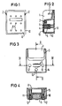
- Figures 1 to 4 show the support in a bottom view, a section in the longitudinal direction, a plan view and a section in the transverse direction.
- the support for the handset which contains all display and selection devices, has cuboid shape and consists of a plate-shaped lower part 8 and a cap-shaped upper part 10 surrounding the lower part 8 at the edge.
- Lower part 8 and upper part 10 are connected to one another by screws 11, which are inserted into recesses in upper part 10 and in sleeve-shaped projections 15 on the inside of the lower part 8 engage.
- the edition is designed so that it only corresponds to about a third the size of the handset.
- the upper part of the upper part 10 has a recess 1 which is matched to the earpiece part of the handset.
- existing wedges 2 are arranged in vertically extending slots 3 of the upper part 10 of the support made of soft material, preferably plastic. This compensates for any lateral play between the handset and the support.
- the lower, raised part 14 of the cap-shaped upper part 10 is provided with two parallel slot-shaped recesses 6 and a cup-shaped shape underneath.
- two holding plates 4 with an interposed magnet 5 are arranged from the underside in such a way that they protrude through the two slots 6 on the top of the support and hold a steel plate inserted in the handset and thus hold the handset itself in place by the magnetic effect.
- the holding plates 4 are movably arranged in the support for tolerance compensation and thus allow a flat contact of the top of the holding plates with the steel plate inserted in the handset.
- the function of the fork switch is achieved in that an additional magnet 7, preferably a round magnet, inserted into a cavity of the upper part 10 actuates a reed relay arranged in a suitable position in the handset, which thus enables the call to be set up.
- this round magnet 7, via a second reed relay arranged in the handset when the handset is lifted, regulates the maximum volume of an incoming call signal when it is on-hook so that no painful stimuli arise for the user during a conversation.
- the plate-shaped lower part 8 has a series of bores 9, by means of which the support is fastened to a mounting surface in the vehicle by means of screws. After the lower part 8 has been fastened to the fastening surface, the lower part 8 is screwed to the upper part 10 of the support. The depressions for receiving the two screws 11 in the upper part 10 are then closed by two cover caps 12 which project over the top of the support.
- a third, as well as the cover caps 12 made of soft material, which protrudes somewhat from the top of the support, fulfills the purpose with the two other cover caps 12 to form a counter bearing to the two magnetic retaining plates, which also protrude, in order to rattle during the journey to avoid.
Landscapes
- Engineering & Computer Science (AREA)
- Signal Processing (AREA)
- Telephone Set Structure (AREA)
- Fittings On The Vehicle Exterior For Carrying Loads, And Devices For Holding Or Mounting Articles (AREA)
- Telephone Function (AREA)
Claims (8)
- Support pour l'écouteur d'un radiotéléphone, dans lequel l'écouteur est maintenu dans une position fixe au moyen d'un aimant disposé dans le support et d'une plaque en matériau magnétique insérée dans l'écouteur, caractérisé par une partie inférieure en forme de plaque (8), dont l'étendue longitudinale correspond approximativement au tiers de la lonngueur de l'écouteur et ne dépasse pas la largeur de ce dernier, et une partie supérieure en forme de capot (10), pouvant être montée sur la partie inférieure et comportant, dans sa partie destinée à loger la partie de l'écouteur contenant la capsule réceptrice, un renfoncement de forme correspondante (1) et, dans sa partie surélevée (14), deux ouvertures en forme de fentes et une partie sous-jacente en forme de pot, dans laquelle deux tôles de maintien mobiles (4), entre lesquelles est intercalé un aimant (5), sont disposées de manière à traverser les deux fentes (6) de la face supérieure du support et adhèrent à la plaque magnétique, située en vis-à-vis, de l'écouteur.
- Support suivant la revendication 1, caractérisé par le fait que des coins (2) réalisés en un matériau mou, de préférence en matière plastique, sont disposés dans la zone d'application latérale de l'écouteur dans le renfoncement (1), dans des fentes verticales (3) de la partie supérieure (10) du support.
- Support suivant la revendication 1 ou 2, caractérisé par le fait que la partie inférieure (8) du support comporte, au niveau de la surface tournée vers la partie supérieure (10), des embouts saillants en forme de douilles (15), dans lesquels s'engagent des vis (11) reliant la partie supérieure (10) à la partie inférieure (8).
- Support suivant la revendication 3, caractérisé par le fait que des ouvertures ménagées dans la partie supérieure (10) servant à loger les vis (11) sont fermées par des bouchons de fermeture (12) qui sont disposés en saillie sur la surface.
- Support suivant la revendication 4, caractérisé par le fait qu'il est en outre prévu un autre capuchon de fermeture (13) qui fait saillie sur la surface de la partie supérieure.
- Support suivant la revendication 4 ou 5, caractérisé par le fait que les capuchons de fermeture (12,13) sont réalisés en un matériau mou.
- Support suivant l'une des revendications 1 à 6, caractérisé par le fait que dans l'espace intérieur de la partie supérieure (10) est disposé un autre aimant (7), qui actionne un relais à lame disposé dans une position correspondante dans l'écouteur.
- Support suivant l'une des revendications précédentes, caractérisé par le fait que la fixation dans le véhicule est réalisée par vissage de la partie inférieure (8) sur une surface de fixation.
Applications Claiming Priority (2)
| Application Number | Priority Date | Filing Date | Title |
|---|---|---|---|
| DE3443645 | 1984-11-29 | ||
| DE3443645 | 1984-11-29 |
Publications (3)
| Publication Number | Publication Date |
|---|---|
| EP0183268A2 EP0183268A2 (fr) | 1986-06-04 |
| EP0183268A3 EP0183268A3 (en) | 1987-09-02 |
| EP0183268B1 true EP0183268B1 (fr) | 1991-11-06 |
Family
ID=6251524
Family Applications (1)
| Application Number | Title | Priority Date | Filing Date |
|---|---|---|---|
| EP85115105A Expired - Lifetime EP0183268B1 (fr) | 1984-11-29 | 1985-11-28 | Berceau pour l'écouteur d'un poste téléphonique pour voiture |
Country Status (7)
| Country | Link |
|---|---|
| US (1) | US4747136A (fr) |
| EP (1) | EP0183268B1 (fr) |
| DE (2) | DE8435049U1 (fr) |
| DK (1) | DK550985A (fr) |
| FI (1) | FI80178C (fr) |
| NO (1) | NO164749C (fr) |
| ZA (1) | ZA859108B (fr) |
Families Citing this family (7)
| Publication number | Priority date | Publication date | Assignee | Title |
|---|---|---|---|---|
| US5128994A (en) * | 1990-03-15 | 1992-07-07 | Mitsubishi Denki Kabushiki Kaisha | Telephone handset with magnetic holder |
| US5109411A (en) * | 1990-06-21 | 1992-04-28 | Scientific Dimensions | Telephone handset cradle mount |
| US5060260A (en) * | 1990-07-24 | 1991-10-22 | Connell Joseph J O | Mounting cradle for a portable cellular telephone |
| DE59207039D1 (de) * | 1991-06-27 | 1996-10-10 | Bosch Gmbh Robert | Auflage für einen Fernsprechhandapparat |
| JPH07203012A (ja) * | 1993-12-28 | 1995-08-04 | Hashimoto Corp | 留守番機能を有する自動車電話用付属装置。 |
| US5588055A (en) * | 1995-01-27 | 1996-12-24 | Williamson; Robert | Telephone holder with mounting assembly |
| WO2004100505A1 (fr) * | 2003-05-09 | 2004-11-18 | Miikka Valkonen | Dispositif pour faciliter l'utilisation d'un telephone mobile dans un vehicule |
Family Cites Families (9)
| Publication number | Priority date | Publication date | Assignee | Title |
|---|---|---|---|---|
| US2623128A (en) * | 1946-03-15 | 1952-12-23 | Automatic Telephone & Elect | Telephone instrument with magnetic handset latch |
| DE849118C (de) * | 1951-04-12 | 1952-09-11 | Hermann Dipl-Ing Dr Tiefenbach | Fernsprechapparat |
| DE1214735B (de) * | 1964-04-23 | 1966-04-21 | Siemens Ag | Umschalter fuer Fernsprechstationen |
| GB1144485A (en) * | 1966-05-10 | 1969-03-05 | Ass Elect Ind | Improvements relating to telephone instruments |
| DE2009599A1 (de) * | 1970-03-02 | 1971-09-16 | Tekade Felten & Guilleaume | Unfallsicheres Fernsprechteilnehmer gerat, insbesondere fur Fahrzeuganlagen |
| IT983689B (it) * | 1973-04-06 | 1974-11-11 | Carava C | Citofono con cornetta scatola d aggancio e interruttore autto matico del circuito fonico |
| US4472606A (en) * | 1982-07-22 | 1984-09-18 | Motorola Inc. | Mobile radio-telephone handset and holder |
| US4581490A (en) * | 1983-12-22 | 1986-04-08 | Richard Genender | Wall telephone assembly |
| US4609785A (en) * | 1985-04-29 | 1986-09-02 | General Electric Company | Universal handset mount |
-
1984
- 1984-11-29 DE DE8435049U patent/DE8435049U1/de not_active Expired
-
1985
- 1985-11-15 US US06/798,307 patent/US4747136A/en not_active Expired - Fee Related
- 1985-11-25 NO NO854707A patent/NO164749C/no unknown
- 1985-11-28 DK DK550985A patent/DK550985A/da not_active Application Discontinuation
- 1985-11-28 ZA ZA859108A patent/ZA859108B/xx unknown
- 1985-11-28 DE DE8585115105T patent/DE3584611D1/de not_active Expired - Lifetime
- 1985-11-28 FI FI854713A patent/FI80178C/fi not_active IP Right Cessation
- 1985-11-28 EP EP85115105A patent/EP0183268B1/fr not_active Expired - Lifetime
Also Published As
| Publication number | Publication date |
|---|---|
| NO854707L (no) | 1986-05-30 |
| NO164749B (no) | 1990-07-30 |
| DK550985A (da) | 1986-05-30 |
| DE3584611D1 (de) | 1991-12-12 |
| DK550985D0 (da) | 1985-11-28 |
| NO164749C (no) | 1990-11-07 |
| FI80178B (fi) | 1989-12-29 |
| EP0183268A2 (fr) | 1986-06-04 |
| DE8435049U1 (de) | 1986-05-22 |
| EP0183268A3 (en) | 1987-09-02 |
| FI80178C (fi) | 1990-04-10 |
| US4747136A (en) | 1988-05-24 |
| FI854713L (fi) | 1986-05-30 |
| FI854713A0 (fi) | 1985-11-28 |
| ZA859108B (en) | 1986-07-30 |
Similar Documents
| Publication | Publication Date | Title |
|---|---|---|
| DE19817302C1 (de) | Einbauvorrichtung für Fahrzeuge | |
| DE69029440T2 (de) | Tragbares Funktelefon | |
| EP0156297A2 (fr) | Appareil mobile pour transmission radio | |
| EP0808256A1 (fr) | Combine telephonique particulierement destine a etre utilise dans un vehicule | |
| WO2000041380A1 (fr) | Telephone, notamment telephone mobile pour enfants | |
| EP1134108B1 (fr) | Tableau de bord modulaire pour véhicule à moteur | |
| DE19850044C2 (de) | Mobiltelefon-Halterung für ein Fahrzeug | |
| DE8310739U1 (de) | Bedienteil für ein Autotelefon | |
| DE7736254U1 (de) | Schalter fuer innenleuchten von kraftfahrzeugen | |
| EP0183268A2 (fr) | Berceau pour l'écouteur d'un poste téléphonique pour voiture | |
| DE19538249A1 (de) | Halterungsvorrichtung für ein Funktelefon in einem Fahrzeug | |
| DE69129380T2 (de) | Aufnahmevorrichtung für ein tragbares Telefon | |
| EP0822693B1 (fr) | Dispositif mains-libres pour téléphones dans des véhicules automobiles | |
| DE4110768C1 (fr) | ||
| EP0319108B1 (fr) | Combiné, en particulier pour un radiotéléphone | |
| DE3015050B1 (de) | Bediengeraet fuer ein Mobilfunkgeraet | |
| DE2943374C2 (de) | Telefon-Handapparat für ein Funkgerät für den mobilen Einsatz | |
| DE2902052C2 (fr) | ||
| EP0394747A2 (fr) | Fixation pour un appareil radio | |
| DE2919599A1 (de) | Sperrvorrichtung fuer fernsprechgeraete | |
| DE3700554A1 (de) | Autoradio | |
| DE19501774C2 (de) | Fernsprechapparat | |
| DE29921189U1 (de) | Mobiles Notrufgerät | |
| DE3402597A1 (de) | Bediengeraet fuer mobile funkfernsprechgeraete | |
| DE29618839U1 (de) | Mobilfunkgerät |
Legal Events
| Date | Code | Title | Description |
|---|---|---|---|
| PUAI | Public reference made under article 153(3) epc to a published international application that has entered the european phase |
Free format text: ORIGINAL CODE: 0009012 |
|
| AK | Designated contracting states |
Kind code of ref document: A2 Designated state(s): AT BE CH DE FR GB IT LI LU NL SE |
|
| PUAL | Search report despatched |
Free format text: ORIGINAL CODE: 0009013 |
|
| AK | Designated contracting states |
Kind code of ref document: A3 Designated state(s): AT BE CH DE FR GB IT LI LU NL SE |
|
| 17P | Request for examination filed |
Effective date: 19880205 |
|
| 17Q | First examination report despatched |
Effective date: 19900528 |
|
| RBV | Designated contracting states (corrected) |
Designated state(s): DE |
|
| GRAA | (expected) grant |
Free format text: ORIGINAL CODE: 0009210 |
|
| AK | Designated contracting states |
Kind code of ref document: B1 Designated state(s): DE |
|
| REF | Corresponds to: |
Ref document number: 3584611 Country of ref document: DE Date of ref document: 19911212 |
|
| PGFP | Annual fee paid to national office [announced via postgrant information from national office to epo] |
Ref country code: DE Payment date: 19920128 Year of fee payment: 7 |
|
| PLBE | No opposition filed within time limit |
Free format text: ORIGINAL CODE: 0009261 |
|
| STAA | Information on the status of an ep patent application or granted ep patent |
Free format text: STATUS: NO OPPOSITION FILED WITHIN TIME LIMIT |
|
| 26N | No opposition filed | ||
| PG25 | Lapsed in a contracting state [announced via postgrant information from national office to epo] |
Ref country code: DE Effective date: 19930803 |