EP0183412A2 - Appareil d'enregistrement et de reproduction de données sur un milieu d'enregistrement magnétique - Google Patents
Appareil d'enregistrement et de reproduction de données sur un milieu d'enregistrement magnétique Download PDFInfo
- Publication number
- EP0183412A2 EP0183412A2 EP85308122A EP85308122A EP0183412A2 EP 0183412 A2 EP0183412 A2 EP 0183412A2 EP 85308122 A EP85308122 A EP 85308122A EP 85308122 A EP85308122 A EP 85308122A EP 0183412 A2 EP0183412 A2 EP 0183412A2
- Authority
- EP
- European Patent Office
- Prior art keywords
- recording
- magnetic
- head
- gaps
- reading
- Prior art date
- Legal status (The legal status is an assumption and is not a legal conclusion. Google has not performed a legal analysis and makes no representation as to the accuracy of the status listed.)
- Withdrawn
Links
Images


Classifications
-
- G—PHYSICS
- G11—INFORMATION STORAGE
- G11B—INFORMATION STORAGE BASED ON RELATIVE MOVEMENT BETWEEN RECORD CARRIER AND TRANSDUCER
- G11B5/00—Recording by magnetisation or demagnetisation of a record carrier; Reproducing by magnetic means; Record carriers therefor
- G11B5/012—Recording on, or reproducing or erasing from, magnetic disks
-
- G—PHYSICS
- G11—INFORMATION STORAGE
- G11B—INFORMATION STORAGE BASED ON RELATIVE MOVEMENT BETWEEN RECORD CARRIER AND TRANSDUCER
- G11B15/00—Driving, starting or stopping record carriers of filamentary or web form; Driving both such record carriers and heads; Guiding such record carriers or containers therefor; Control thereof; Control of operating function
- G11B15/02—Control of operating function, e.g. switching from recording to reproducing
- G11B15/12—Masking of heads; circuits for Selecting or switching of heads between operative and inoperative functions or between different operative functions or for selection between operative heads; Masking of beams, e.g. of light beams
-
- G—PHYSICS
- G11—INFORMATION STORAGE
- G11B—INFORMATION STORAGE BASED ON RELATIVE MOVEMENT BETWEEN RECORD CARRIER AND TRANSDUCER
- G11B5/00—Recording by magnetisation or demagnetisation of a record carrier; Reproducing by magnetic means; Record carriers therefor
- G11B5/02—Recording, reproducing, or erasing methods; Read, write or erase circuits therefor
-
- G—PHYSICS
- G11—INFORMATION STORAGE
- G11B—INFORMATION STORAGE BASED ON RELATIVE MOVEMENT BETWEEN RECORD CARRIER AND TRANSDUCER
- G11B5/00—Recording by magnetisation or demagnetisation of a record carrier; Reproducing by magnetic means; Record carriers therefor
- G11B5/127—Structure or manufacture of heads, e.g. inductive
- G11B5/265—Structure or manufacture of a head with more than one gap for erasing, recording or reproducing on the same track
- G11B5/2652—Structure or manufacture of a head with more than one gap for erasing, recording or reproducing on the same track with more than one gap simultaneously operative
- G11B5/2654—Structure or manufacture of a head with more than one gap for erasing, recording or reproducing on the same track with more than one gap simultaneously operative for recording or erasing
- G11B5/2655—Structure or manufacture of a head with more than one gap for erasing, recording or reproducing on the same track with more than one gap simultaneously operative for recording or erasing with all the gaps disposed within the track or "guard band" between tracks, e.g. with erase gaps operative on track edges, with wide erase gap followed by narrow write gap
-
- G—PHYSICS
- G11—INFORMATION STORAGE
- G11B—INFORMATION STORAGE BASED ON RELATIVE MOVEMENT BETWEEN RECORD CARRIER AND TRANSDUCER
- G11B5/00—Recording by magnetisation or demagnetisation of a record carrier; Reproducing by magnetic means; Record carriers therefor
- G11B5/48—Disposition or mounting of heads or head supports relative to record carriers ; arrangements of heads, e.g. for scanning the record carrier to increase the relative speed
- G11B5/488—Disposition of heads
- G11B5/4886—Disposition of heads relative to rotating disc
Definitions
- the present invention relates to apparatus for recording and reproducing data on a magnetic recording medium, for example a disk or a tape, having a plurality of recording tracks, which are concentric in the case of a disk and parallel in the case of a tape.
- the apparatus is of the type that comprises at least one magnetic head and a mechanism for positioning the head with respect to the tracks of the magnetic recording medium.
- each magnetic head is provided either with a single gap for recording and reading the information concerned ("single gap” type), or with two independent gaps, one for recording and one for reading (“read after write” type), disposed in such a way that they are both transverse to the longitudinal axis of the recording track and centered on the axis.
- erasing gaps may be disposed at the sides of the recording gap for "cleaning up” the recorded signal thereby defining a recording "tunnel".
- the length of the recording gap of the head is normally a little smaller than the width of the track of the magnetic recording medium.
- the width of the tracks determines the packing density of tracks, normally expressed in tracks per inch (t.p.i.).
- the magnetic heads used for reading magnetic recording media with a packing density of 48 t.p.i. have recording and reading gaps of about 317 pm long, with at the sides, two erasing gaps which are each about 150 ⁇ m in length.
- the magnetic heads which are used for reading magnetic recording media with a packing density of 96 t.p.i. however have reading and recording gaps about 159 um long, with, at the sides, two erasing gaps which are each about 80 pm in length.
- the mechanisms for positioning the head with respect to the disk are therefore controlled in such a way as to move the head by distances which are linked to the packing density. That means that, in the apparatuses for handling disks with a packing density of 48 t.p.i., the stepping movement of the head is over a distance of 529 pm, while in the case of apparatus for dealing with disks with a packing density of 96 t.p.i., the stepping movement of the head is 264.5 um.
- Apparatus according to the invention is characterised in that the magnetic head comprises at least two recording and reading gaps, that the gaps are of different lengths and that switching means are operable to activate the recording and reading gaps one at a time.
- apparatus 20 for recording and reproducing data on a magnetic recording medium 21 comprises a base 22 on which a spindle 23 is rotatably mounted.
- the spindle 23 is rotated by an electric motor 25 which is fixed to the base 22.
- the magnetic recording medium 21 is in the form of a disk of flexible type, having a central hole 26 by means of which it can be engaged with the spindle 23 to be driven in rotation.
- the disk 21 is provided with two magnetised surfaces 27 on each of which is disposed a plurality of recording tracks 29 (see Figure 2) concentric with respect to the axis of rotation 28 of the disk 21.
- a first magnetic head 30 (see Figure 1) for recording and reading data on the underneath surface of the magnetic head 21 is mounted on a carriage 31 which is movable with respect to the base 22 under the influence of guides 33.
- a second magnetic head 32 is mounted at the end of an arm 34 which is pivotally mounted on a lug 35 on the carriage 31, and is disposed opposite the head 30, for recording and reading data on the upper surfce of the magnetic disk 21.
- An electric stepping motor 36 which is fixed to the base 22, is provided for controlling the movement of the carriage 31 and movement of the heads 30 and 32 radially with respect to the magnetic disk 1, by means of a cylindrical hub 37 and a pair of flexible blades 38 and 39 of known type, for example of the type described in the applicants' European patent application No 52477.
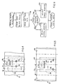
- An electronic control circuit 40 (see Figure 3) is capable of controlling the electric motors 25 and 36 and governing the flow of data from and to the magnetic heads 30 and 32, on the basis of control data which reach it on a channel 41 from a user unit to which the apparatus 20 may be connected.
- the user unit is not shown in the drawings and may be for example a processor.
- the circuit 40 comprises a translator 42 for the stepping motor 36, a logic unit 43 which distributes the instructions which arrive from the channel 41 to the motor 25 and to the translator 42, and a circuit 44 for amplifying the recording and reading signals, being connected to both the heads 30 and 32 and, by way of a channel 45, to the unit to which the apparatus 20 is connected.
- the circuit 40 comprises switching means 46 which comprise for example a diverter and which are operable to select activation of the recording and reading cores of the magnetic heads 30 and 32, as will be described in greater detail hereinafter, on the basis of a control signal HS which arrives on the channel 41 from the unit using the apparatus 20.
- Each magnetic head 30 and 32 comprises a first magnetic recording and reading core 50 (see Figures 6, 7 and 8), a second magnetic recording and reading core 51, and four magnetic erasing cores 52, 53, 54 and 55.
- the magnetic core 50 is formed by two shaped portions 60 and 61 which are coupled together to define a gap 62 of a predetermined length L 1 .
- a coil 62 is wound in turns around the portion 60 and an element 64 closes the magnetic circuit between the portions 60 and 61.
- the magnetic core 51 is formed by two shaped portions 66 and 67 which are coupled together in such a way as to define a gap 68 of a predetermined length L 2 .
- a coil 69 is wound in turns around the portion 67 and an element 70 closes the magnetic circuit between the portions 66 and 67.
- the magnetic cores 52 and 53 each comprise two shaped portions 72 and 73 which are coupled together to define gaps 74 and 75 respectively, of a predetermined length L 3 .
- Each core 52 and 53 further comprises a coil 76 which is wound in turns around the portion 73 and an element 77 which connects the portions 72 and 73 together to close the magnetic circuit.
- the magnetic cores 54 and 55 each comprise two shaped portions 80 and 81 which are connected together in such a way as to define respective gaps 82 and 83 of a predetermined length L 4 ,
- Each core 54 and 55 further comprises a coil 85 wound in turns around the portion 81, and an element 86 which connects the portions 80 and 81 together to close the magnetic circuit.
- the portions 60, 61, 66, 67, 72, 73, 80 and 81 and the elements 64, 70, 77 and 86 are all of ferromagnetic material, for example Mn-Zn ferrite.
- a first ceramic shield 90 is interposed between the core 50 and the core 51, a second ceramic shield 91 is interposed between the core 51 and the cores 52 and 53 and a third ceramic shield 92 is interposed between the cores 52 and 53 and the cores 54 and 55.
- the lengths L 1 , L 2 , L3 and L4 of the gaps 62, 68, 74, 75, 82 and 83 are determined in dependence on the width of the recording tracks on the magnetic recording medium which is to be used.
- the pitch or centre-to-centre spacing P 1 (see Figure 4) between the tracks 29 is 529 ⁇ m while in the case of a high packing density (I H ) of 96 t.p.i., the pitch or centre-to-centre spacing P 2 ( Figure 5) between the tracks is 264.5 ⁇ m.
- IS standardised or normal packing density
- I H high packing density
- L l 15 9 p m ;
- L 2 137 ⁇ m;
- L 3 79 ⁇ m; and
- L 4 152 ⁇ m.
- the magnetic disk 21 on which data is to be recorded or from which data is to be read is mounted on the spindle 23 and centered with respect to the axis of rotation 28.
- the control circuit 40 activates the motor 25 to rotate the disk 21.
- the operation 150 of Fig 9 Before recording and/or reading data, on the basis of instructions which arrive from the user unit by means of the channel 41, (the operation 150 of Fig 9) it performs the operation 151 for selecting the packing density.
- the control circuit 40 activates the stepping motor 36 so as to bring the head 30 into register with a reference track, for example the most outward of the tracks 29 (operation 152).
- the items of information which are pre-recorded on the reference track are then read (operation 153).
- Operation 154 determines whether or not the disk 21 is recorded with a high packing density (I H ) ' In the affirmative, the switching means 46 select the magnetic cores 50, 52 and 53 (operation 155), while in the negative case the magnetic cores 51, 54 and 55 are selected (operation 157).
- the magnetic heads 30 and 32 are enabled for reading and/or recording data by means of their cores 50 and associated gaps 62, with the erasing cores 52 and 53 and associated gaps 74 and 75 activated to "clean up" the signal while in the second situation (shown in Figure 5) the magnetic heads 30 and 32 are enabled for reading and/or recording data by means of their cores 51 and associated gaps 68, with the erasing cores 54 and 55 and associated gaps 82 and 83 activated.
- the user unit controls the stepping motor 36 to cause it to produce stepping movements of the heads 30 and 32 equal to the pitch P 1 in the case of the high packing density (I H ) and equal to the pitch P 2 in the case of normal packing (IS).
- the user unit may also determine the packing density with which data are recorded by controlling the apparatus 20 by means of the head selection signal HS.
- apparatus is capable of recording and reading magnetic disks with different radial packing densities, because each magnetic head comprises at least two reading and recording gaps of different widths, and switching means are operable for selectively activating the gaps one at a time.
- Each head 30 and 32 could have mgnetic cores formed and arranged differently to the forms and arrangements described, and could also comprise other recording and reading gaps, of respective lengths.
Landscapes
- Engineering & Computer Science (AREA)
- Manufacturing & Machinery (AREA)
- Digital Magnetic Recording (AREA)
- Signal Processing For Digital Recording And Reproducing (AREA)
- Recording Or Reproducing By Magnetic Means (AREA)
Applications Claiming Priority (2)
| Application Number | Priority Date | Filing Date | Title |
|---|---|---|---|
| IT68144/84A IT1180134B (it) | 1984-11-15 | 1984-11-15 | Dispositivo di registrazione e riproduzione di dati su un supporto magnetico |
| IT6814484 | 1984-11-15 |
Publications (2)
| Publication Number | Publication Date |
|---|---|
| EP0183412A2 true EP0183412A2 (fr) | 1986-06-04 |
| EP0183412A3 EP0183412A3 (fr) | 1987-09-16 |
Family
ID=11308146
Family Applications (1)
| Application Number | Title | Priority Date | Filing Date |
|---|---|---|---|
| EP85308122A Withdrawn EP0183412A3 (fr) | 1984-11-15 | 1985-11-07 | Appareil d'enregistrement et de reproduction de données sur un milieu d'enregistrement magnétique |
Country Status (4)
| Country | Link |
|---|---|
| US (1) | US4805051A (fr) |
| EP (1) | EP0183412A3 (fr) |
| JP (1) | JPS62121903A (fr) |
| IT (1) | IT1180134B (fr) |
Cited By (3)
| Publication number | Priority date | Publication date | Assignee | Title |
|---|---|---|---|---|
| EP0289984A3 (en) * | 1987-05-06 | 1989-11-23 | Deutsche Thomson-Brandt Gmbh | Recording apparatus with tracking control |
| EP0478256A1 (fr) * | 1990-09-27 | 1992-04-01 | Kabushiki Kaisha Toshiba | Tête magnétique |
| EP0423661A3 (en) * | 1989-10-20 | 1993-08-04 | Insite Peripherals, Inc. | Dual magnetic head and method for writing on very high track density and conventional track density floppy disk |
Families Citing this family (18)
| Publication number | Priority date | Publication date | Assignee | Title |
|---|---|---|---|---|
| JP2635550B2 (ja) * | 1986-03-31 | 1997-07-30 | 株式会社東芝 | 磁気記録再生装置 |
| JPS63161508A (ja) * | 1986-12-25 | 1988-07-05 | Toshiba Corp | フロツピ−デイスク装置の磁気ヘツド装置 |
| US4933795A (en) * | 1987-12-07 | 1990-06-12 | Fujitsu America, Inc. | Floppy disc read and write head having two separate read and write cores for multiple track density and recording frequencies |
| US4977471A (en) * | 1987-12-07 | 1990-12-11 | Fujitsu America, Inc. | Method for servo formatting disc media for a floppy disk drive |
| US4984103A (en) * | 1987-12-07 | 1991-01-08 | Fujitsu America, Inc. | Method for reading/writing for a floppy disc drive with buffer memory |
| JP2655871B2 (ja) * | 1988-04-07 | 1997-09-24 | アルプス電気株式会社 | 複合型磁気ヘッド |
| JPH0249207A (ja) * | 1988-08-09 | 1990-02-19 | Nec Corp | 磁気ヘッド |
| JPH02263301A (ja) * | 1989-03-31 | 1990-10-26 | Toshiba Corp | フロッピーディスク装置のヘッド制御装置及びヘッド制御方法 |
| US5107385A (en) * | 1989-11-16 | 1992-04-21 | Applied Magnetics Corporation | Read head assembly for multiple-width tracks |
| US5063468A (en) * | 1990-05-08 | 1991-11-05 | North American Philips Corporation | Compatible magnetic head assembly |
| JPH04143911A (ja) * | 1990-10-05 | 1992-05-18 | Canon Electron Inc | 磁気ヘッド |
| US5285341A (en) * | 1990-12-17 | 1994-02-08 | Canon Kabushiki Kaisha | Thin film magnetic head |
| US5257149A (en) * | 1991-02-13 | 1993-10-26 | Seagate Technology, Inc. | Disc drive with offset address field |
| GB2255221B (en) * | 1991-04-25 | 1996-01-03 | Mitsubishi Electric Corp | Magnetic head apparatus |
| GB2279800B (en) * | 1991-04-25 | 1996-01-03 | Mitsubishi Electric Corp | Magnetic head apparatus |
| FR2722024B1 (fr) * | 1994-07-01 | 1996-08-02 | Thomson Consumer Electronics | Circuits magnetiques pour ensemble de tetes magnetiques d'enregistrement/lecture |
| US6091559A (en) * | 1994-12-19 | 2000-07-18 | Mobile Storage Technology Inc. | Variable zone layout and track pitch parameter considerations for information storage disk drive |
| US7342741B1 (en) | 2000-02-10 | 2008-03-11 | Esgw Holdings Limited | Disk drive with variable track density |
Family Cites Families (4)
| Publication number | Priority date | Publication date | Assignee | Title |
|---|---|---|---|---|
| US4068268A (en) * | 1976-01-08 | 1978-01-10 | Idemoto Tom Y | Method and apparatus for writing servo-tracks on rotating magnetic memory surfaces |
| US4298897A (en) * | 1979-09-20 | 1981-11-03 | International Business Machines Corporation | Buffered recording |
| IT1129852B (it) * | 1980-11-14 | 1986-06-11 | Olivetti & Co Spa | Apparecchiatura per registrare dischi magnetici flessibili |
| DE3376903D1 (en) * | 1982-10-01 | 1988-07-07 | Mitsubishi Electric Corp | Disc drive for flexible discs with different track widths |
-
1984
- 1984-11-15 IT IT68144/84A patent/IT1180134B/it active
-
1985
- 1985-11-07 EP EP85308122A patent/EP0183412A3/fr not_active Withdrawn
- 1985-11-08 JP JP60250587A patent/JPS62121903A/ja active Pending
-
1988
- 1988-01-04 US US07/142,273 patent/US4805051A/en not_active Expired - Fee Related
Cited By (4)
| Publication number | Priority date | Publication date | Assignee | Title |
|---|---|---|---|---|
| EP0289984A3 (en) * | 1987-05-06 | 1989-11-23 | Deutsche Thomson-Brandt Gmbh | Recording apparatus with tracking control |
| EP0423661A3 (en) * | 1989-10-20 | 1993-08-04 | Insite Peripherals, Inc. | Dual magnetic head and method for writing on very high track density and conventional track density floppy disk |
| EP0478256A1 (fr) * | 1990-09-27 | 1992-04-01 | Kabushiki Kaisha Toshiba | Tête magnétique |
| US5331492A (en) * | 1990-09-27 | 1994-07-19 | Kabushiki Kaisha Toshiba | Magnetic disk system having a magnetoresistive head provided therein |
Also Published As
| Publication number | Publication date |
|---|---|
| IT8468144A1 (it) | 1986-05-15 |
| US4805051A (en) | 1989-02-14 |
| JPS62121903A (ja) | 1987-06-03 |
| EP0183412A3 (fr) | 1987-09-16 |
| IT1180134B (it) | 1987-09-23 |
| IT8468144A0 (it) | 1984-11-15 |
Similar Documents
| Publication | Publication Date | Title |
|---|---|---|
| US4805051A (en) | Apparatus for recording and reproducing data on a magnetic recording medium | |
| CA1147054A (fr) | Appareil d'enregistrement a memoire tampon | |
| US7082007B2 (en) | Method to achieve higher track density by allowing only one-sided track encroachment | |
| US6188532B1 (en) | Backward compatible head and head positioning assembly for a linear digital tape drive | |
| US6445521B1 (en) | Write current optimization in a disc drive system | |
| US4803571A (en) | Floppy disc magnetic head apparatus compatible with both horizontal and perpendicular recording media | |
| EP0110050B1 (fr) | Unité de disques pour disques souples à différentes largeurs de piste | |
| EP1156485A3 (fr) | Dispositif et procédé pour la commande d'une unité à disques magnétiques | |
| KR19990077163A (ko) | 4채널 방위 및 2채널 무-방위 기록-후-판독의 종방향 자기 헤드 | |
| JPH04232610A (ja) | 情報の読み取り・書き込み装置 | |
| US6342986B2 (en) | Servo writing with simultaneous biasing of magneto-resistive read elements | |
| GB1571175A (en) | Magnetic transducer apparatus | |
| KR100464433B1 (ko) | 헤드의 열 운동과 인접 트랙 잠식 효과를 구분하기 위한방법 및 장치 | |
| JPS619806A (ja) | 磁気デイスク記録装置 | |
| US6724558B2 (en) | Servo writing in a disc drive with substantially identical heads having read and write elements in a radial offset position | |
| KR100618884B1 (ko) | 디스크 드라이브의 서보 정보 기록 방법 | |
| EP0997871B1 (fr) | Magasin amovible à disque dur et magnétoresistif, entraínement à disque et salves enfouies d'asservissement en quadrature | |
| KR100574941B1 (ko) | 하드디스크 드라이브를 위한 서보 기록 방법 | |
| US4074331A (en) | Magnetic recording head structure for recording on both sides of a record member | |
| US4442463A (en) | Safeguarding of data recorded on disk by tunnel erase magnetic head assembly | |
| KR100505576B1 (ko) | 모델에 따른 테이블 정보가 기록된 하드디스크를 구비한 하드디스크 드라이브 | |
| EP0174714A1 (fr) | Stucture de tête de transducteur magnétique et son procédé d'utilisation | |
| CA2108523A1 (fr) | Unite de disque magnetique et commande par positionneur | |
| JPH0524561B2 (fr) | ||
| TW358949B (en) | Magnetic disc device with dummy write function |
Legal Events
| Date | Code | Title | Description |
|---|---|---|---|
| PUAI | Public reference made under article 153(3) epc to a published international application that has entered the european phase |
Free format text: ORIGINAL CODE: 0009012 |
|
| AK | Designated contracting states |
Kind code of ref document: A2 Designated state(s): DE FR GB |
|
| PUAL | Search report despatched |
Free format text: ORIGINAL CODE: 0009013 |
|
| RHK1 | Main classification (correction) |
Ipc: G11B 5/02 |
|
| AK | Designated contracting states |
Kind code of ref document: A3 Designated state(s): DE FR GB |
|
| 17P | Request for examination filed |
Effective date: 19880303 |
|
| 17Q | First examination report despatched |
Effective date: 19890712 |
|
| STAA | Information on the status of an ep patent application or granted ep patent |
Free format text: STATUS: THE APPLICATION IS DEEMED TO BE WITHDRAWN |
|
| 18D | Application deemed to be withdrawn |
Effective date: 19891124 |
|
| RIN1 | Information on inventor provided before grant (corrected) |
Inventor name: FEHL, ALESSANDRO Inventor name: DE MARCO, GIULIANO |