EP0183626B1 - Récepteur de télévision à prépaiement - Google Patents
Récepteur de télévision à prépaiement Download PDFInfo
- Publication number
- EP0183626B1 EP0183626B1 EP85402347A EP85402347A EP0183626B1 EP 0183626 B1 EP0183626 B1 EP 0183626B1 EP 85402347 A EP85402347 A EP 85402347A EP 85402347 A EP85402347 A EP 85402347A EP 0183626 B1 EP0183626 B1 EP 0183626B1
- Authority
- EP
- European Patent Office
- Prior art keywords
- data
- advance
- key
- user
- payment
- Prior art date
- Legal status (The legal status is an assumption and is not a legal conclusion. Google has not performed a legal analysis and makes no representation as to the accuracy of the status listed.)
- Expired - Lifetime
Links
Images


Classifications
-
- G—PHYSICS
- G07—CHECKING-DEVICES
- G07F—COIN-FREED OR LIKE APPARATUS
- G07F17/00—Coin-freed apparatus for hiring articles; Coin-freed facilities or services
- G07F17/0014—Coin-freed apparatus for hiring articles; Coin-freed facilities or services for vending, access and use of specific services not covered anywhere else in G07F17/00
-
- H—ELECTRICITY
- H04—ELECTRIC COMMUNICATION TECHNIQUE
- H04N—PICTORIAL COMMUNICATION, e.g. TELEVISION
- H04N21/00—Selective content distribution, e.g. interactive television or video on demand [VOD]
- H04N21/20—Servers specifically adapted for the distribution of content, e.g. VOD servers; Operations thereof
- H04N21/25—Management operations performed by the server for facilitating the content distribution or administrating data related to end-users or client devices, e.g. end-user or client device authentication, learning user preferences for recommending movies
- H04N21/254—Management at additional data server, e.g. shopping server, rights management server
- H04N21/2543—Billing, e.g. for subscription services
-
- H—ELECTRICITY
- H04—ELECTRIC COMMUNICATION TECHNIQUE
- H04N—PICTORIAL COMMUNICATION, e.g. TELEVISION
- H04N21/00—Selective content distribution, e.g. interactive television or video on demand [VOD]
- H04N21/40—Client devices specifically adapted for the reception of or interaction with content, e.g. set-top-box [STB]; Operations thereof
- H04N21/43—Processing of content or additional data, e.g. demultiplexing additional data from a digital video stream; Elementary client operations, e.g. monitoring of home network or synchronising decoder's clock; Client middleware
- H04N21/433—Content storage operation, e.g. storage operation in response to a pause request, caching operations
-
- H—ELECTRICITY
- H04—ELECTRIC COMMUNICATION TECHNIQUE
- H04N—PICTORIAL COMMUNICATION, e.g. TELEVISION
- H04N21/00—Selective content distribution, e.g. interactive television or video on demand [VOD]
- H04N21/40—Client devices specifically adapted for the reception of or interaction with content, e.g. set-top-box [STB]; Operations thereof
- H04N21/47—End-user applications
- H04N21/472—End-user interface for requesting content, additional data or services; End-user interface for interacting with content, e.g. for content reservation or setting reminders, for requesting event notification, for manipulating displayed content
- H04N21/47211—End-user interface for requesting content, additional data or services; End-user interface for interacting with content, e.g. for content reservation or setting reminders, for requesting event notification, for manipulating displayed content for requesting pay-per-view content
-
- H—ELECTRICITY
- H04—ELECTRIC COMMUNICATION TECHNIQUE
- H04N—PICTORIAL COMMUNICATION, e.g. TELEVISION
- H04N21/00—Selective content distribution, e.g. interactive television or video on demand [VOD]
- H04N21/40—Client devices specifically adapted for the reception of or interaction with content, e.g. set-top-box [STB]; Operations thereof
- H04N21/47—End-user applications
- H04N21/488—Data services, e.g. news ticker
- H04N21/4882—Data services, e.g. news ticker for displaying messages, e.g. warnings, reminders
-
- H—ELECTRICITY
- H04—ELECTRIC COMMUNICATION TECHNIQUE
- H04N—PICTORIAL COMMUNICATION, e.g. TELEVISION
- H04N7/00—Television systems
- H04N7/16—Analogue secrecy systems; Analogue subscription systems
- H04N7/167—Systems rendering the television signal unintelligible and subsequently intelligible
- H04N7/1675—Providing digital key or authorisation information for generation or regeneration of the scrambling sequence
Definitions
- the present invention relates to a receiver for pay television and more particularly to a payment control apparatus for a pay television system.
- a broadcast center i.e., a broadcast station
- the user calls the center by a predetermined data before a desired program is to be broadcast (e.g., a week or a day beforehand) so as to reserve the desired program, if any.
- the center sends an ID signal to a user who has reserved the corresponding program.
- a scrambled program signal is descrambled by the decoder.
- a pay per view status signal is sent from the center to each user.
- the user wishes to watch a program represented by the pay per view status signal, he depresses a pay per view switch arranged in a decoder in a tuner.
- the scrambled program is then descrambled, and the user can watch the program.
- charge data corresponding to the subscribed program is stored in a memory in the decoder.
- the center periodically checks the contents of the memory of each decoder through a telephone line and collects fees or bills the charge.
- This conventional pay per view system can solve the drawbacks of the first conventional system.
- the center since the center must periodically check the memories of all users, the check system is complicated.
- fee collection is performed through a telephone line, an audio dial unit and a modem (modulator/demodulator) are required, so that the user terminal and the station apparatus are complex and high-cost.
- Another pay per view system is proposed.
- a user deposits an advance money to the broadcast station through a bank or the like, and the broadcast station sends the advance data together with ID (or address) data to the user via a PCM area of a TV broadcast channel.
- the advance data representing the deposit is stored in the advance memory of the receiver of the user. Every time the user watches a pay program, a program fee is subtracted from the advance data.
- no modem for connecting the receiver to the telephone line is required.
- a fee collection system using a telephone line need not be installed in the broadcast center. It simplifies the system configuration.
- the TV broadcast channel since the TV broadcast channel is used as a charge link, an error may occur in the advance information due to atmospheric or airplane noise.
- the sending end i.e., the broadcast center
- the broadcast center cannot detect a transmission error.
- the present invention solves the conventional drawbacks described above. It is an object of this invention to provide a pay per view system wherein an advance information error can be detected at a receiving end or at a user's terminal, and a feedback path can be substantially formed to acknowledge the error so that the broadcast center corrects the error.
- a payment control apparatus for a pay television system in which a subscriber purchases viewing time by advance payment to a broadcast center from which pay television programs are sent and are controllably made accessible to said subscriber as a function of said advance payment, said broadcast center being operatively connected to a bank through which said subscriber effects advance payment and transmitting information relative thereto in the form of advance payment data, said apparatus being at the location of said subscriber and comprising : a detector receiving iterated data sequences addressed thereto from said broadcast center relative to said advance payment; a memory coupled to said detector for storing said data relative to said advance payment; a controller connected to said detector comprising means for checking whether the received iterated data sequence contains an error with respect to said transmitted data sequence, said error being detected when fewer than half of said information iterations received coincide with each other, and display means operatively connected to said controller to signal an error message when incorrectly received data has been fed into said memory, so that said user can inform said broadcast center and ask for said
- an advance data transmission error can be acknowledged to the broadcast station.
- the present invention will be described with reference to an embodiment which exemplifies an information transmission system utilizing a broadcast satellite channel.
- the present invention may be applied to a normal TV broadcast system or a CATV (cable television) system.
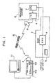
- Fig. 1 is a block diagram of a pay per view system utilizing a DBS (Direct Broadcast Satellite) channel.
- a direct broadcast wave from a broadcast satellite 10 is received by a parabolic antenna 2 and is demodulated by a DBS tuner 1.
- the broadcast signal subjected to predetermined scrambling and transmitted to a tuner is decoded (descrambled) by a decoder in the tuner.
- the descrambled program is watched by a user on a television monitor 11.
- each user i.e., a subscriber deposits advance money with a cash card 5 or the like from a bank 3 to a broadcast center 6.
- the advance data is transmitted from a computer 4 of the bank 3 to a computer 7 to of the broadcast center 6.
- the advance data or deposit data is then transmitted from the center 6 to the user through a broadcast satellite link by utilizing a PCM data area or a vertical blanking period of a TV signal.
- Each data is assigned with an individual user's ID code, and composite data is transmitted from a transmitter 8 to the broadcast satellite 10 through a transmitting parabolic antenna 9.
- the data is then sent from the broadcast satellite 10 to the tuner 1 of each user through the receiving parabolic antenna 2.
- the tuner 1 (decoder) of each user has an advance memory for storing the advance data deposited by the user through the bank.
- the advance data is displayed on a data display unit 102 in the tuner 1.
- a "pay per view" program status data is supplied from the broadcast center 6 to the user through the broadcast satellite channel upon broadcasting.
- the user wishes to watch this pay program, he performs channel selection and a key code input for execution of pay per view with a ten-key pad 101 or the like in the tuner.
- the decoder de-scrambles the scrambled program to be watched on a television monitor 11.
- Fig.2 is a front view of an operation panel of the DBS tuner 1 of Fig. 1
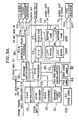
- Figs. 3 and 3A is a block diagram of the tuner 1 (indoor unit).
- the tuner 1 When the user depresses a power switch 100 on the operation panel, the tuner 1 is set in the standby state, and a standby LED 102f in the display unit 102 is turned on.
- a DBS reception signal is supplied to a tuning circuit 12.
- the DBS reception signal is tuned and detected by the tuning circuit 12 and is supplied as a video signal, e.g., an NTSC signal to a video processing system.
- An output from the tuner circuit 12 is also supplied as a detection output to an output terminal T7.
- Tuning is performed at the ten-key pad 101, and a micro-computer 13 for tuning control supplies a tuning signal to the tuning circuit 12 through a PLL prescaler unit 14 in response to tuning operation data.
- a channel number is displayed by a channel display LED 102a (Fig.2) in the display unit 102.
- a polarization discrimination signal from the micro-computer 13 appears as a control output at an output terminal T8 through a polarization control amplfier 21.
- the control output is supplied to an outdoor unit 5SHF-to-UHF converter) built into the parabolic antenna 2.
- a high-frequency PCM area component of the video signal as an output from the tuner circuit 12 is eliminated by a low)pass filter (LPF) 15.
- LPF low)pass filter
- the scrambled signal is de-scrambled by a de-scrambling circuit 16.
- the spectrum of a signal transmitted with energy dispersal restores the original spectrum by means of an anti-dispersal circuit 17.
- An output from the anti-dispersal circuit 17 appears at a video output at an output terminal T3 through a clamper 18.
- An output at the output terminal T3 is supplied to the television monitor 11.
- a video output from the anti-dispersal circuit 17 is modulated by an RF modulator 19 to an RF signal of a proper channel frequency.
- the RF signal is supplied from an RF output terminal T2 to the VTR through an RF switch 20.
- An antenna reception signal of a VHF or UHF television broadcast wave is also supplied from an input terminal T1 to the RF switch 20.
- the VHF or UHF television broadcast signal and the RF output are switched and selectively supplied to the terminal T2.
- This switching operation is performed by a DBS/TV switching button 103 of Fig.2.
- a DBS LED 104 is turned on in synchronism with the switching button 103.
- PCM area data included in the high-frequency component of the output from the tuner circuit 12 is extracted by a band-pass filter (BPF) 22.
- BPF band-pass filter
- the extracted 4-phase 5QPSK) modulated data is demodulated by a QPSK decoder 23 and is supplied to a PCM processor 24.
- Fig.4 is a one-frame format of an output from the decoder 23.
- a control code such as a stereo/monaural code is sent following a data sync (SYNC).
- SYNC data sync
- Program status data i.e., free program, pay program by reservation, or pay per view program discrimination status data
- Program status data follow the scramble status data.
- the PCM processor 24 de-interleaves the data of Fig. 4 in response to an output from a RAM 25 for storing de-interleaving data and also performs error correction in accordance with/error collection code.
- the PCM processor 24 de-scrambles audio data in accordance with the scramble status data.
- the scrambled data is also supplied to the video de-scrambling circuit 16, so that the video signal is de-scrambled.
- Processed outputs from the PCM processor 24 appears as L-and R-channel audio outputs at output terminals T5 and T6 through a D/A converter 26, a stereo/monaural audio switch 27, low-pass filters 28L and 28R and buffer amplifiers 29L and 29R.
- an audio selection button 105 Upon operation of an audio selection button 105 in the operation panel of Fig. 2, one of the four audio data (1) to (4) can be selected.
- a selection number is indicated by ON states of LEDs 102b in the display unit 102.
- the station number of the DBS broadcast and the stereo/monaural mode are indicated by the LEDs 102c.
- step 1 the PCM processor 24 detecting this status data in step 1 causes the pay per view LED 102g to flicker, for acknowledging the subscriber that the current program is a pay per view program.
- the subscriber When the subscriber wishes to watch this program, he enters a key code with the ten-key pad 101 of the tuner 1 in step 2.
- the entered key code is supplied from the micro-computer 13 to a pay per view micro-computer 31.
- the entered key code is compared for identification with a user-defined code registered in a key code memory 32 in step 3.
- the program fee is subtracted from the advance data in an advance memory 34.
- predetermined de-scrambling is performed, and the subscriber can watch the desired program (step 5).
- the fee data transmitted from the broadcast station is stored in a fee memory 33 and is displayed on the TV screen for a short period of time, e.g., three seconds.
- a fee button 106 in the operation panel of Fig. 2 the program fee can be displayed at any time on the screen during program listening.
- the program fee is subtracted from the advance data in the advance memory 34.
- the advance data is updated in the advance memory 34.
- the deposit data is transmitted from the broadcast center together with the subscriber address data by utilizing the free area of the PCM data, as indicated in the data format of Fig. 4.
- the PCM processor 24 compares (identifies) the transmitted address data with the subscriber address data stored in the ROM 35.
- the deposit data and the deposition date data are decoded (step 8), and the decoded data are stored in the advance memory 34 (step 9).
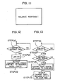
- a balance sheet of the advance memory 34 can be displayed on the screen any time, as shown by a flow chart of Fig. 7 (steps 11 and 12).
- the display contents are the deposit mount, the deposit date and the balance for each channel.
- the subscriber can deposit an additional advance by checking the balance displayed on the television screen and judges whether or not an additional advance is required.
- the contents of the advance memory 34 are transferred from the pay per view micro-computer 31 to a message micro-computer 36.
- An output from the message micro-computer 36 is converted by a character generator 37 to a display signal.
- the display signal is thus displayed on the television screen.
- the character generator 37 is operated in response to a sync signal from a sync separator 38.
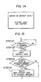
- an error display LED 102d in the display unit 102 in the operation panel of Fig. 2 is turned on in step 14 in the flow chart of Fig. 9.
- a redeposit request i.e., balance shortage status data
- the message micro-computer 36 detects the balance shortage status (step 17) and supplies the balance shortage message data to the character generator 37 (step 18) when the balance button 107 is depressed in step 16, as shown in a flow chart of Fig.10.
- the character generator 37 generates a character display signal corresponding to the message data.
- the character display signal is superposed on the video signal from the anti-dispersal circuit 17.
- the superposed signal is displayed as a message on the television screen.
- a predetermined period of time e.g. 10 seconds
- the pay per view micro-computer 31 checks whether or not there is an error in the deposit advance data transmitted from the broadcast center 6. The error check is performed by decision by majority. Identical data is transmitted five consecutive times. When three out of five data coincide with each other, the pay per view micro-computer 31 determines that no transmission error occurs in deposit data. However, when only two data are detected to be coincident with remaining three data being inconsistent, the micro-computer 31 determines that transmission error occurs in deposit data. When the micro-computer 31 determines in step 20 that a data transmission error occurred, as shown in the flow chart of Fig. 12, the operation panel error display LED 102d flickers in step 21 and error status flag data is supplied to the message micro-computer 36 in step 22.
- the message micro-cpmputer 36 detects the data error status (step 24) and supplies to the character generator 37 a message representing that "error in deposit data! in step 25.
- the message shown in Fig. 14 is displayed on the television screen in accordance with the output from the character generator 37.
- the balance statement is displayed in step 26 in the same manner as in Fig. 8. The user calls the center after checking the balance statement and asks for the deposit data to be resent.
- the deposit data is sent again, and the correct deposit data is stored in the advance memory 34.
- the broadcast center 6 cannot catch that a tansmission error actually occurs. Double deposit money entry may be performed due to a false claim for data transmission error. For this reason, the pay per view micro-computer 31 prevents double advance money entry by referring to advance deposit date data transmitted together with the deposit data.
- a deposit serial number data can be transmitted together with the advance data, so that the advance data can be stored in the memory 34 only when the advance serial number data is incremented.
- the subscriber address is compared with a destination address attached to the message data.
- the message is stored in a RAM 39 through the message micro-computer 36. Message reception is indicated by the message LED 102e in the display unit 102 of Fig. 2.
- the subscriber When the subscriber notices that the LED 102e is turned on, he depresses a message button 108 in the operation panel.
- the message data is read out from the RAM 39, and the readout data is supplied to the character generator 37 through the message micro-computer 36.
- the character signal output is displayed as message characters on the display screen. This display can be cancelled upon depression of the message button 108 again.
- a clear button 109 in the operation panel is depressed, the message data can be erased from the RAM 39.
- the messsage RAM 39 has an area for storing the program schedule transmitted by utilizing the free area of the PCM data.
- the program schedule data is supplied from the PCM processor 24 and is stored in the RAM 39 through the message micro-computer 36.
- the data read out from the RAM 39 is converted by the character generator 37 to a character signal as a video signal.
- the program schedule is displayed on the television screen.
- data of the advance money deposited by the user is transmitted from the broadcast station and is stored in the advance memory of the user, and the program fee is subtracted from the advance data stored in the advance memory every time the user watches a pay program.
- the user can watch desired programs any time without reservations.
- the broadcast center need not install an expensive fee collection system using, for example, a telephone line, but needs only a simple charge system which transmits deposit data and program fee data to the user through the broadcast channel.
- data transmission error is detected and displayed on the diplay unit or television screen. Even if the broadcast center cannot detect the transmission error since a one-way broadcast channel is used in the charge system, the user can find the trqnsmission error and call the broadcast center to ask for the error to be corrected. In other words, even if a one-way communication path is used, a substitute for feedback path for transmission error correction can be substantially constituted. It provides a charge system with high reliability.
Landscapes
- Engineering & Computer Science (AREA)
- Multimedia (AREA)
- Signal Processing (AREA)
- Databases & Information Systems (AREA)
- Physics & Mathematics (AREA)
- General Physics & Mathematics (AREA)
- Computer Security & Cryptography (AREA)
- Human Computer Interaction (AREA)
- Two-Way Televisions, Distribution Of Moving Picture Or The Like (AREA)
Claims (6)
- Appareil de commande de paiement pour système de télévision payant dans lequel un abonné achète du temps de vision par paiement préalable à un centre de diffusion (6) par lequel des émissions de télévision payantes sont envoyées et sont rendues accessibles de façon contrôlable audit abonné en fonction dudit paiement préalable, ledit centre de diffusion (6) étant fonctionnellement relié à une banque (3) par l'intermédiaire de laquelle ledit abonné a effectué le paiement préalable et transmettant l'information relative à celui-ci sous la forme d'une donnée de paiement d'avance, ledit appareil étant placé chez ledit abonné et comprenant :- un détecteur (24) recevant des séquences de données répétées qui lui sont adressées en provenance dudit centre de diffusion (6) relativement audit paiement d'avance ;- une mémoire (34) couplée audit détecteur (24) servant à emmagasiner ladite donnée relative audit paiement d'avance ;- un dispositif de commande (31) connecté audit détecteur (24) et comprenant un moyen qui sert à contrôler si la séquence de données répétée reçue contient une erreur en ce qui concerne ladite séquence de donnée transmise, ladite erreur étant détectée lorsque moins de la moitié desdites répétitions d'information reçues coîncident entre elles ; et- un moyen d'affichage (102d) fonctionnellement connecté audit dispositif de commande (31) de façon à présenter un message d'erreur lorsqu'une donnée incorrectement reçue a été délivrée à ladite mémoire, de sorte que ledit utilisateur peut informer ledit centre de diffusion (6) et demander que ladite donnée de paiement d'avance soit envoyée de nouveau.
- Appareil de commande de paiement selon la revendication 1, caractérisé en ce que ladite donnée de paiement d'avance comprend une séquence de données dans laquelle l'information relative audit paiement d'avance est répétée un nombre prédéterminé de fois, et en ce que ledit moyen de contrôle d'erreur comprend un moyen de décision majoritaire qui détecte ladite erreur lorsque moins de la moitié desdites répétitions de l'information reçues coîncident entre elles.
- Appareil de commande de paiement selon la revendication 2, caractérisé en ce que ladite information relative audit paiement d'avance est répétée cinq fois, ladite erreur étant affichée lorsque moins de trois répétitions d'information reçues coîncident entre elles.
- Appareil de commande de paiement selon la revendication 1, caractérisé en ce qu'il comporte en outre un moyen (16) permettant de désembrouiller une émission sélectionnée parmi les émissions de télévision transmises depuis le centre (6), et un moyen de commande servant à soustraire les droits relatifs à l'émission de télévision de la donnée d'avance emmagasinée dans ladite mémoire d'avance (34) lors de la réception de ladite émission de télévision.
- Appareil de commande de paiement selon l'une quelconque des revendications 1 à 3, caractérisé en ce qu'il comprend en outre un moyen servant à commander l'accès audit système de télévision payant grâce à l'utilisation d'un code numérique propre à l'utilisateur, ledit moyen comprenant :- un dispositif d'entrée numérique (101) par lequel une séquence numérique peut être introduite par ledit utilisateur ;- une mémoire de code numérique (32) servant à enregistrer ledit code numérique propre à l'utilisateur ;- ledit dispositif de commande (31) étant fonctionnellement connecté à ladite mémoire de code numérique et audit dispositif d'entrée numérique (101) afin de comparer ledit code numérique propre à l'utilisateur qui a été enregistré avec ladite séquence numérique introduite sur ledit dispositif d'entrée numérique ;- ledit dispositif de commande étant également fonctionnellement connecté audit appareil de commande de paiement afin de n'autoriser l'accès à une émission payante qu'en cas de coîncidence de ladite séquence numérique avec ledit code numérique propre à l'utilisateur qui a été enregistré.
- Appareil de commande de paiement selon la revendication 5, caractérisé en ce que ledit moyen de limitation d'accès commande le fonctionnement du moyen de désembrouillage (16) et dudit moyen de soustraction de droits après comparaison dudit code numérique propre à l'utilisateur et de ladite donnée venant dudit dispositif d'entrée numérique (101).
Priority Applications (1)
| Application Number | Priority Date | Filing Date | Title |
|---|---|---|---|
| AT85402347T ATE68653T1 (de) | 1984-11-29 | 1985-11-29 | Abonnementsfernsehempfaenger. |
Applications Claiming Priority (4)
| Application Number | Priority Date | Filing Date | Title |
|---|---|---|---|
| JP252185/84 | 1984-11-29 | ||
| JP252186/84 | 1984-11-29 | ||
| JP25218684A JPS61129990A (ja) | 1984-11-29 | 1984-11-29 | 有料放送用テコ−ダ |
| JP25218584A JPS61129989A (ja) | 1984-11-29 | 1984-11-29 | 有料放送用受信装置 |
Publications (3)
| Publication Number | Publication Date |
|---|---|
| EP0183626A2 EP0183626A2 (fr) | 1986-06-04 |
| EP0183626A3 EP0183626A3 (en) | 1987-09-02 |
| EP0183626B1 true EP0183626B1 (fr) | 1991-10-16 |
Family
ID=26540588
Family Applications (1)
| Application Number | Title | Priority Date | Filing Date |
|---|---|---|---|
| EP85402347A Expired - Lifetime EP0183626B1 (fr) | 1984-11-29 | 1985-11-29 | Récepteur de télévision à prépaiement |
Country Status (4)
| Country | Link |
|---|---|
| US (1) | US4809325A (fr) |
| EP (1) | EP0183626B1 (fr) |
| CA (1) | CA1257377A (fr) |
| DE (1) | DE3584425D1 (fr) |
Families Citing this family (56)
| Publication number | Priority date | Publication date | Assignee | Title |
|---|---|---|---|---|
| JPH0246082A (ja) * | 1988-08-08 | 1990-02-15 | Pioneer Electron Corp | Cctv装置における課金表示システム |
| JPH02128588A (ja) * | 1988-11-09 | 1990-05-16 | Pioneer Electron Corp | Catv端末装置 |
| US5355480A (en) * | 1988-12-23 | 1994-10-11 | Scientific-Atlanta, Inc. | Storage control method and apparatus for an interactive television terminal |
| USRE36988E (en) * | 1988-12-23 | 2000-12-12 | Scientific-Atlanta, Inc. | Terminal authorization method |
| US5001554A (en) * | 1988-12-23 | 1991-03-19 | Scientific-Atlanta, Inc. | Terminal authorization method |
| CA2553385C (fr) * | 1990-09-10 | 2008-01-15 | Starsight Telecast, Inc. | Interface utilisateur pour systeme de programmation de television |
| JPH0591509A (ja) * | 1991-09-30 | 1993-04-09 | Toshiba Corp | 有料放送の視聴料金徴収システム |
| JP3911047B2 (ja) * | 1996-04-30 | 2007-05-09 | ソニー株式会社 | 録画予約制御システム及び録画予約制御方法 |
| US8656423B2 (en) * | 1999-08-27 | 2014-02-18 | Ochoa Optics Llc | Video distribution system |
| US6647417B1 (en) | 2000-02-10 | 2003-11-11 | World Theatre, Inc. | Music distribution systems |
| US7209900B2 (en) | 1999-08-27 | 2007-04-24 | Charles Eric Hunter | Music distribution systems |
| US7370016B1 (en) | 1999-08-27 | 2008-05-06 | Ochoa Optics Llc | Music distribution systems |
| US6952685B1 (en) * | 1999-08-27 | 2005-10-04 | Ochoa Optics Llc | Music distribution system and associated antipiracy protection |
| US8090619B1 (en) | 1999-08-27 | 2012-01-03 | Ochoa Optics Llc | Method and system for music distribution |
| US7647618B1 (en) | 1999-08-27 | 2010-01-12 | Charles Eric Hunter | Video distribution system |
| US6850901B1 (en) | 1999-12-17 | 2005-02-01 | World Theatre, Inc. | System and method permitting customers to order products from multiple participating merchants |
| WO2001044888A2 (fr) * | 1999-12-17 | 2001-06-21 | World Theatre, Inc. | Systeme et procede permettant a des clients de commander des produits selectionnes dans un large eventail de produits offerts par des commerçants participants multiples |
| US9252898B2 (en) | 2000-01-28 | 2016-02-02 | Zarbaña Digital Fund Llc | Music distribution systems |
| WO2001088801A1 (fr) * | 2000-05-19 | 2001-11-22 | Wilson How Kiap Gueh | Procede et appareil de regulation de l'utilisation d'un contenu electronique ou de l'acces dudit contenu |
| US8112311B2 (en) * | 2001-02-12 | 2012-02-07 | Ochoa Optics Llc | Systems and methods for distribution of entertainment and advertising content |
| US20020112235A1 (en) * | 2001-02-12 | 2002-08-15 | Ballou Bernard L. | Video distribution system |
| US20030061607A1 (en) * | 2001-02-12 | 2003-03-27 | Hunter Charles Eric | Systems and methods for providing consumers with entertainment content and associated periodically updated advertising |
| US20020112243A1 (en) * | 2001-02-12 | 2002-08-15 | World Theatre | Video distribution system |
| US7960005B2 (en) * | 2001-09-14 | 2011-06-14 | Ochoa Optics Llc | Broadcast distribution of content for storage on hardware protected optical storage media |
| US8806533B1 (en) | 2004-10-08 | 2014-08-12 | United Video Properties, Inc. | System and method for using television information codes |
| US8640166B1 (en) | 2005-05-06 | 2014-01-28 | Rovi Guides, Inc. | Systems and methods for content surfing |
| US8387089B1 (en) | 2005-05-06 | 2013-02-26 | Rovi Guides, Inc. | Systems and methods for providing a scan |
| JP2007027824A (ja) * | 2005-07-12 | 2007-02-01 | Aruze Corp | 放送受信装置 |
| JP2009545921A (ja) | 2006-07-31 | 2009-12-24 | ユナイテッド ビデオ プロパティーズ, インコーポレイテッド | メディアガイダンスプランナを提供するためのシステムおよび方法 |
| US8407737B1 (en) | 2007-07-11 | 2013-03-26 | Rovi Guides, Inc. | Systems and methods for providing a scan transport bar |
| US8989561B1 (en) | 2008-05-29 | 2015-03-24 | Rovi Guides, Inc. | Systems and methods for alerting users of the postponed recording of programs |
| US9329966B2 (en) | 2010-11-23 | 2016-05-03 | Echostar Technologies L.L.C. | Facilitating user support of electronic devices using matrix codes |
| US9792612B2 (en) | 2010-11-23 | 2017-10-17 | Echostar Technologies L.L.C. | Facilitating user support of electronic devices using dynamic matrix code generation |
| US9781465B2 (en) | 2010-11-24 | 2017-10-03 | Echostar Technologies L.L.C. | Tracking user interaction from a receiving device |
| US9280515B2 (en) | 2010-12-03 | 2016-03-08 | Echostar Technologies L.L.C. | Provision of alternate content in response to QR code |
| US8886172B2 (en) | 2010-12-06 | 2014-11-11 | Echostar Technologies L.L.C. | Providing location information using matrix code |
| US8875173B2 (en) | 2010-12-10 | 2014-10-28 | Echostar Technologies L.L.C. | Mining of advertisement viewer information using matrix code |
| US9596500B2 (en) | 2010-12-17 | 2017-03-14 | Echostar Technologies L.L.C. | Accessing content via a matrix code |
| US8640956B2 (en) | 2010-12-17 | 2014-02-04 | Echostar Technologies L.L.C. | Accessing content via a matrix code |
| US9148686B2 (en) | 2010-12-20 | 2015-09-29 | Echostar Technologies, Llc | Matrix code-based user interface |
| US8856853B2 (en) | 2010-12-29 | 2014-10-07 | Echostar Technologies L.L.C. | Network media device with code recognition |
| US8292166B2 (en) | 2011-01-07 | 2012-10-23 | Echostar Technologies L.L.C. | Performing social networking functions using matrix codes |
| US8534540B2 (en) | 2011-01-14 | 2013-09-17 | Echostar Technologies L.L.C. | 3-D matrix barcode presentation |
| US8786410B2 (en) | 2011-01-20 | 2014-07-22 | Echostar Technologies L.L.C. | Configuring remote control devices utilizing matrix codes |
| US8553146B2 (en) | 2011-01-26 | 2013-10-08 | Echostar Technologies L.L.C. | Visually imperceptible matrix codes utilizing interlacing |
| US8468610B2 (en) | 2011-01-27 | 2013-06-18 | Echostar Technologies L.L.C. | Determining fraudulent use of electronic devices utilizing matrix codes |
| US9571888B2 (en) | 2011-02-15 | 2017-02-14 | Echostar Technologies L.L.C. | Selection graphics overlay of matrix code |
| US8511540B2 (en) | 2011-02-18 | 2013-08-20 | Echostar Technologies L.L.C. | Matrix code for use in verification of data card swap |
| US8931031B2 (en) * | 2011-02-24 | 2015-01-06 | Echostar Technologies L.L.C. | Matrix code-based accessibility |
| US9367669B2 (en) | 2011-02-25 | 2016-06-14 | Echostar Technologies L.L.C. | Content source identification using matrix barcode |
| US9736469B2 (en) | 2011-02-28 | 2017-08-15 | Echostar Technologies L.L.C. | Set top box health and configuration |
| US8833640B2 (en) | 2011-02-28 | 2014-09-16 | Echostar Technologies L.L.C. | Utilizing matrix codes during installation of components of a distribution system |
| US8550334B2 (en) | 2011-02-28 | 2013-10-08 | Echostar Technologies L.L.C. | Synching one or more matrix codes to content related to a multimedia presentation |
| US8443407B2 (en) | 2011-02-28 | 2013-05-14 | Echostar Technologies L.L.C. | Facilitating placeshifting using matrix code |
| EP2525281B1 (fr) | 2011-05-20 | 2019-01-02 | EchoStar Technologies L.L.C. | Barre de progression améliorée |
| CN115708358B (zh) * | 2021-08-18 | 2025-05-16 | 北京字跳网络技术有限公司 | 一种视频处理方法、装置、设备及存储介质 |
Family Cites Families (9)
| Publication number | Priority date | Publication date | Assignee | Title |
|---|---|---|---|---|
| US3508005A (en) * | 1967-12-18 | 1970-04-21 | Sangamo Weston | Price control and audience monitoring in subscription television and like systems |
| US3863215A (en) * | 1973-07-03 | 1975-01-28 | Rca Corp | Detector for repetitive digital codes |
| CA1153103A (fr) * | 1981-03-19 | 1983-08-30 | Northern Telecom Limited | Brouillage et reconstitution des signaux video dans un systeme de television payante |
| US4484217A (en) * | 1982-05-11 | 1984-11-20 | Telease, Inc. | Method and system for remote reporting, particularly for pay television billing |
| JPS6024791A (ja) * | 1983-06-10 | 1985-02-07 | ジェネラル インストルメント コーポレーション | 視聴料前払いテレビジヨン方法及び装置 |
| AU559311B2 (en) * | 1984-02-15 | 1987-03-05 | Matsushita Electric Industrial Co., Ltd. | Pay tv charge/time data display |
| US4673976A (en) * | 1984-05-31 | 1987-06-16 | American Television & Communications Corporation | Cable television system data verification apparatus |
| US4712238A (en) * | 1984-06-08 | 1987-12-08 | M/A-Com Government Systems, Inc. | Selective-subscription descrambling |
| DE3579785D1 (de) * | 1984-10-31 | 1990-10-25 | Sony Corp | Dekodiereinrichtungen fuer gebuehrenfernsehsysteme. |
-
1985
- 1985-11-28 CA CA000496382A patent/CA1257377A/fr not_active Expired
- 1985-11-29 EP EP85402347A patent/EP0183626B1/fr not_active Expired - Lifetime
- 1985-11-29 DE DE8585402347T patent/DE3584425D1/de not_active Expired - Lifetime
-
1987
- 1987-08-05 US US07/082,999 patent/US4809325A/en not_active Expired - Lifetime
Also Published As
| Publication number | Publication date |
|---|---|
| EP0183626A3 (en) | 1987-09-02 |
| DE3584425D1 (de) | 1991-11-21 |
| CA1257377A (fr) | 1989-07-11 |
| EP0183626A2 (fr) | 1986-06-04 |
| US4809325A (en) | 1989-02-28 |
Similar Documents
| Publication | Publication Date | Title |
|---|---|---|
| EP0183626B1 (fr) | Récepteur de télévision à prépaiement | |
| US5416508A (en) | CATV system with transmission of program schedules, linked program broadcasts, and permissive ordering periods | |
| EP0200310B1 (fr) | Système de transmission directe par satellite | |
| US5465385A (en) | CATV system with an easy program reservation | |
| US5001554A (en) | Terminal authorization method | |
| US5325431A (en) | Looking and listening fee collection system for pay broadcasting | |
| EP0934651A1 (fr) | Procede et dispositif d'emission et de telechargement d'informations d'etablissement | |
| USRE36988E (en) | Terminal authorization method | |
| JP3935963B2 (ja) | 信号処理装置を制御する方法 | |
| JP3122500B2 (ja) | Catvシステム | |
| JPS61129990A (ja) | 有料放送用テコ−ダ | |
| JPH10200847A (ja) | 放送番組記録制御装置 | |
| JPS61129991A (ja) | 有料放送用受信装置 | |
| JPS61129939A (ja) | 情報受信装置 | |
| JPS61129989A (ja) | 有料放送用受信装置 | |
| KR100239136B1 (ko) | 디지탈 dbs의 제한수신 시스템에서 전송메세지 처리 방법 | |
| JPH11187376A (ja) | 衛星放送の課金通信方式及びその方法とチューナ | |
| JPH0549029A (ja) | Tv信号の選局システム | |
| JPH0436511B2 (fr) | ||
| JP3130983B2 (ja) | Catvシステムおよびcatvシステムにおける視聴申込処理制御方法 | |
| JPH0352066Y2 (fr) | ||
| JPH06237232A (ja) | 有料衛星放送システム | |
| JPH03504794A (ja) | 対話型リモート・デイストリビューション・ネットワークを介して加入者ユニットによって受信された、有料のプログラムに対する接続の終了を検出するための装置 | |
| JPS59128884A (ja) | 双方向catvシステムにおける有料番組サ−ビス方式 | |
| JPH05219502A (ja) | 人工衛星からの有料放送に対する課金装置 |
Legal Events
| Date | Code | Title | Description |
|---|---|---|---|
| PUAI | Public reference made under article 153(3) epc to a published international application that has entered the european phase |
Free format text: ORIGINAL CODE: 0009012 |
|
| AK | Designated contracting states |
Kind code of ref document: A2 Designated state(s): AT DE FR GB NL |
|
| PUAL | Search report despatched |
Free format text: ORIGINAL CODE: 0009013 |
|
| AK | Designated contracting states |
Kind code of ref document: A3 Designated state(s): AT DE FR GB NL |
|
| 17P | Request for examination filed |
Effective date: 19871207 |
|
| 17Q | First examination report despatched |
Effective date: 19891208 |
|
| GRAA | (expected) grant |
Free format text: ORIGINAL CODE: 0009210 |
|
| AK | Designated contracting states |
Kind code of ref document: B1 Designated state(s): AT DE FR GB NL |
|
| REF | Corresponds to: |
Ref document number: 68653 Country of ref document: AT Date of ref document: 19911115 Kind code of ref document: T |
|
| REF | Corresponds to: |
Ref document number: 3584425 Country of ref document: DE Date of ref document: 19911121 |
|
| ET | Fr: translation filed | ||
| PLBE | No opposition filed within time limit |
Free format text: ORIGINAL CODE: 0009261 |
|
| STAA | Information on the status of an ep patent application or granted ep patent |
Free format text: STATUS: NO OPPOSITION FILED WITHIN TIME LIMIT |
|
| 26N | No opposition filed | ||
| PGFP | Annual fee paid to national office [announced via postgrant information from national office to epo] |
Ref country code: FR Payment date: 20011113 Year of fee payment: 17 Ref country code: AT Payment date: 20011113 Year of fee payment: 17 |
|
| PGFP | Annual fee paid to national office [announced via postgrant information from national office to epo] |
Ref country code: GB Payment date: 20011128 Year of fee payment: 17 |
|
| PGFP | Annual fee paid to national office [announced via postgrant information from national office to epo] |
Ref country code: NL Payment date: 20011129 Year of fee payment: 17 |
|
| PGFP | Annual fee paid to national office [announced via postgrant information from national office to epo] |
Ref country code: DE Payment date: 20011217 Year of fee payment: 17 |
|
| REG | Reference to a national code |
Ref country code: GB Ref legal event code: IF02 |
|
| PG25 | Lapsed in a contracting state [announced via postgrant information from national office to epo] |
Ref country code: GB Free format text: LAPSE BECAUSE OF NON-PAYMENT OF DUE FEES Effective date: 20021129 Ref country code: AT Free format text: LAPSE BECAUSE OF NON-PAYMENT OF DUE FEES Effective date: 20021129 |
|
| PG25 | Lapsed in a contracting state [announced via postgrant information from national office to epo] |
Ref country code: NL Free format text: LAPSE BECAUSE OF NON-PAYMENT OF DUE FEES Effective date: 20030601 |
|
| PG25 | Lapsed in a contracting state [announced via postgrant information from national office to epo] |
Ref country code: DE Free format text: LAPSE BECAUSE OF NON-PAYMENT OF DUE FEES Effective date: 20030603 |
|
| GBPC | Gb: european patent ceased through non-payment of renewal fee | ||
| PG25 | Lapsed in a contracting state [announced via postgrant information from national office to epo] |
Ref country code: FR Free format text: LAPSE BECAUSE OF NON-PAYMENT OF DUE FEES Effective date: 20030731 |
|
| NLV4 | Nl: lapsed or anulled due to non-payment of the annual fee |
Effective date: 20030601 |
|
| REG | Reference to a national code |
Ref country code: FR Ref legal event code: ST |