EP0183675B1 - Dispositif pour assembler des poutres latéralement en utilisant des connecteurs - Google Patents
Dispositif pour assembler des poutres latéralement en utilisant des connecteurs Download PDFInfo
- Publication number
- EP0183675B1 EP0183675B1 EP85890248A EP85890248A EP0183675B1 EP 0183675 B1 EP0183675 B1 EP 0183675B1 EP 85890248 A EP85890248 A EP 85890248A EP 85890248 A EP85890248 A EP 85890248A EP 0183675 B1 EP0183675 B1 EP 0183675B1
- Authority
- EP
- European Patent Office
- Prior art keywords
- beams
- support
- rollers
- plates
- home
- Prior art date
- Legal status (The legal status is an assumption and is not a legal conclusion. Google has not performed a legal analysis and makes no representation as to the accuracy of the status listed.)
- Expired
Links
- 238000003825 pressing Methods 0.000 claims description 43
- 238000010276 construction Methods 0.000 description 3
- 238000000034 method Methods 0.000 description 2
- 230000015572 biosynthetic process Effects 0.000 description 1
- 239000000969 carrier Substances 0.000 description 1
- 239000002131 composite material Substances 0.000 description 1
- 230000006835 compression Effects 0.000 description 1
- 238000007906 compression Methods 0.000 description 1
- 238000004519 manufacturing process Methods 0.000 description 1
- 238000005096 rolling process Methods 0.000 description 1
- 239000000725 suspension Substances 0.000 description 1
- 239000002023 wood Substances 0.000 description 1
Images


Classifications
-
- B—PERFORMING OPERATIONS; TRANSPORTING
- B27—WORKING OR PRESERVING WOOD OR SIMILAR MATERIAL; NAILING OR STAPLING MACHINES IN GENERAL
- B27F—DOVETAILED WORK; TENONS; SLOTTING MACHINES FOR WOOD OR SIMILAR MATERIAL; NAILING OR STAPLING MACHINES
- B27F7/00—Nailing or stapling; Nailed or stapled work
- B27F7/15—Machines for driving in nail- plates and spiked fittings
- B27F7/155—Machines for driving in nail- plates and spiked fittings for nail plates
-
- Y—GENERAL TAGGING OF NEW TECHNOLOGICAL DEVELOPMENTS; GENERAL TAGGING OF CROSS-SECTIONAL TECHNOLOGIES SPANNING OVER SEVERAL SECTIONS OF THE IPC; TECHNICAL SUBJECTS COVERED BY FORMER USPC CROSS-REFERENCE ART COLLECTIONS [XRACs] AND DIGESTS
- Y10—TECHNICAL SUBJECTS COVERED BY FORMER USPC
- Y10S—TECHNICAL SUBJECTS COVERED BY FORMER USPC CROSS-REFERENCE ART COLLECTIONS [XRACs] AND DIGESTS
- Y10S100/00—Presses
- Y10S100/913—Truss presses
Definitions
- the invention relates to a device for pressing nail plates into adjoining beams or the like, with a device for pressing the beams together or the like, into which the nail plate (s) is (are) to be pressed, in which device the beams to be connected or the like. be pressed against an abutment and with at least one device which can be actuated independently of this and is arranged on a bow-shaped support for pressing the nail plates into the pressed bars or the like, which has pressure plates arranged opposite one another, at least one of which can be pushed forward by a drive motor, the direction of action of the device for pressing together the abutting beams or the like. perpendicular to the direction of action of the device for pressing in the nail plate (s).
- a device for connecting adjacent beams which has a device for pressing the beams to be connected together, has become known from SU-A-852 548.
- the device for compressing the beams is rigidly attached to the device, so that the beams always rest with a surface on the stationary abutment. If the total width of the beams to be connected (measured in the direction of action of the compression device) is different, problems arise with the alignment of the nail plate press-in arrangement with respect to the beams.
- a device of the type mentioned in the preamble of independent claim 1 is known from SU-A-703 327.
- This known device has a device for pressing the beams into which the nail plate is to be pressed against an abutment. Furthermore, a device arranged on a bow-shaped support for pressing the nail plate into the bars pressed against one another is provided, which has pressure plates arranged opposite one another, one of which can be advanced by a drive motor.
- the direction of action of the device for pressing the bars together is perpendicular to the direction of action of the device for pressing in the nail plate.
- the object of the invention is to provide an easily transportable device, which can also be carried out by hand, with the aid of which nail plates can be pressed into wooden beams on construction sites or any other place, the beams being clamped together during the nailing process and not having to be moved.
- a device is provided according to the invention, which is characterized in that the device for pressing the bars or the like. is mounted on an auxiliary frame connected to the carrier, that the auxiliary frame is held on a guide provided on the carrier, pivotable and / or movable up and down relative to the carrier, and that the carrier is guided by guide members such as rollers, runners or the like. or the like along the bars. is movable, the rollers on the top of the bar or in a known manner on one of the bars or the like. unroll the parallel guide rail or the rollers on the floor or along U-rails.
- the device according to the invention has the advantage that it can be moved in the longitudinal direction of the beams to be connected, which is much simpler and, above all, more space-saving than moving long and heavy beams in their longitudinal direction.
- the collet Due to the special design of the device for clamping together (“collet”) of the device according to the invention, the collet can be swung out from around the bars, which simplifies the handling of the device according to the invention. Furthermore, the special mounting of the collet has the advantage that it can adjust freely to the beams to be connected to one another, so that the position of the device is not changed when clamping. With the help of the collet designed according to the invention, the bars are clamped together immediately before the nail plates are pressed in, at a short distance from the nail location.
- the like on the subframe of the device for pressing together the beams to be connected below an abutment rigidly connected to the subframe and above one that can be advanced using a pressure medium motor. Pressure plate is arranged. It is preferred that the carrier has a longer leg and that the guide for the auxiliary frame is arranged on the longer leg of the carrier.
- the measure proposed according to the invention has the advantage that the center of the pressure plates for pressing in the nail plates can also be centered relative to the contact surface of the beams, even with beams of different thicknesses.
- This adjustment can be carried out with the aid of a pressure medium motor or it is provided according to the invention that the rollers on the carrier are adjustably fastened transversely to the direction of action of the device for pressing in the nail plate (s), for example with the aid of a spindle drive.
- rollers are provided on the support pointing downwards, which bear against the upper of the beams to be connected from above.
- an embodiment has proven to be advantageous in which the rollers on the carrier are adjustably fastened transversely to the direction of action of the device for pressing in the nail plate (s), for example with the aid of a spindle drive.
- the guide rail or the like for the rollers provided upward on the carrier. is fastened to a holder which has supports for the beams to be connected to one another.
- the pressure plates are mounted on the support so that they can be adjusted in height together with the drive motors which actuate them.
- Invention thus represents e.g. Hydraulic nail pliers are available, which can be supplied with pressure medium from a remote hydraulic unit via pressure hoses, the nail pliers using a pressure cylinder pressing a limited-moving platter against a fixed, optionally pivotable abutment.
- the nail pliers or the like can be by means of rollers. on the beam to be nailed, or a subframe arranged parallel to it, which is attached at beam height, below or above, or on rails or simply on the floor.
- the pliers are fed by hand or by means of driven rollers as a self-propelled device.
- the collet namely its bow-shaped support, is designed so that the arm with the abutment can be swung out and then locked again when moving past any obstacles, such as side-mounted supports, consoles, etc.
- the nail plates are removed at the specified intervals before pressing e.g. tacked by hammer blows. Nail plates with extended tack nails are particularly advantageous for this.
- the bars are pressed together with the aid of the tensioning device provided in the device, so that they abut one another.
- the distance between the pressure plates of the device for pressing in the nail plate to the rollers can be adjusted with the aid of a spindle or hydraulically, so that the center of the plate comes to lie in the area of the contact surface of the beams.
- Either the support members and / or the pressure plates - these can be adjustable with their pressure medium motors if necessary.
- Two handles are placed at a distance to guide the device, and a trestle with an inclined plane or a winch for lifting the device can be used to insert it at bar height.
- the beams are placed on trestles, slants, etc., so that they are roughly horizontal and the device is supported by the rollers on the top of the upper beam and is easy to move.
- the device can also have the rollers arranged so that they are supported on an optional rail. It is also possible to provide an elongated frame with holders for supporting the beams, which has a guide rail parallel to these, along which the device can be moved.
- the guide rail can be arranged in any position relative to the beams, this guide rail is preferably attached at a distance above the beam, similar to a suspension track, in order to keep the working area as free as possible.
- the device can also be used so that the bars are placed side by side for nailing.
- the collet for pressing the beams to be joined together can also be designed differently than previously described.
- the device of the type mentioned can also be characterized in that the device for pressing the bars or the like. has at least one pressure medium motor connected to the carrier, which is mounted approximately in the middle of the carrier, which acts against the upper of the beams to be connected and which or the like. presses against an abutment and that the carrier via guide members, such as rollers, runners or the like. or the like along the bars. is movable, the rollers on the top of the bar or in a known manner on one of the bars or the like. unroll the parallel guide rail or the rollers on the floor or along U-rails.
- This embodiment is characterized by great simplicity without impairing the function.
- the abutments can be designed differently.
- the rollers rolling on the floor can be provided at the free ends of the carrier and for the abutment to be a transverse rod which engages underneath the beams and is preferably detachably fixed to the legs of the carrier.
- guide members such as rollers, runners or the like, engage at the free ends of the carrier in U-rails fastened to the floor.
- the webs of the U-rails are aligned upright and the guide members engage from outside or preferably from the inside in the U-rails and that as a lower abutment of the device for pressing the beams to be joined together, supports arranged on the floor for the beams are provided.
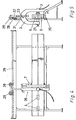
- FIGS. 1, 2 and 3 The embodiment of the device 1 according to the invention (“nail pliers”) shown in FIGS. 1, 2 and 3 has a carrier 2 which, in the exemplary embodiment shown, is designed as an essentially U-shaped bracket. On the carrier 2 is a device 3 for pressing nail plates 4 into beams or the like. made of wood 5 and 6 and further a device 7 in the form of a collet for pressing the beams 5 and 6 together at least during the pressing in of the nail plates 4.
- the device 3 comprises two pressure plates 12, one of which can be pushed onto the beams 5 and 6 by a pressure medium cylinder 9, which can be pressurized with pressure medium via a line 11.
- the other pressure plate 12 ' is guided on the carrier 2 in a guide 8 and can be adjusted in the desired position (corresponding to the width of the bars 5 and 6) by means of an adjusting device 10. If the pressure plate 12 is advanced, then the nail plates 4 are pressed into the beams 5, 6 by the pressure plates 12 and 12 '.
- the device 7 for pressing the bars 5 and 6 together during the pressing of nail plates 4 into the bars 5 and 6 has an auxiliary frame 14 which is slidably mounted on a guide 13 relative to the carrier 2 and which has an abutment 15 at the bottom and a pressure medium motor 16 at the top, wherein the piston rod 17 of the pressure medium motor 16 has a pressure plate 18 which can be pushed onto the abutment 15 in order to compress the beams 5, 6.
- the pressure medium motor 16 can be acted upon with pressure medium via a line 19.
- the auxiliary frame 14 is pivotably supported on the guide 13 relative to the carrier 2, so that the device 7 can be pivoted away from its operative position (dashed position in FIG. 2).
- the leg 20 of the carrier 2, on which the guide 13 for the device 7 is arranged, has a joint 21, so that the device 1 can be tilted, the pressure plate 12 'moving away from the beams 5 and 6, so that the device 1 on beams, brackets and the like protruding from the beams 5 and 6. can be moved past.
- the free pivotability of the leg 20 of the carrier 2 is prevented by inserting a bolt 22.
- the device 1 can be moved along the bars 5 and 6, its carrier 2 is equipped with rollers 23 which abut the upper bar 5 from above.
- the holder 24 for the rollers 23 is adjustable with the aid of a screw 25 or with the aid of a pressure medium cylinder (not shown) relative to the carrier 2, so that the device 1 can be aligned with the beams 5 and 6 such that the pressure plates 12 of the device 3 are always centered with respect to the contact surface between the bars 5 and 6 when nail plates 4 are to be pressed in.
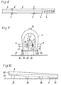
- the embodiment of the device 26 according to the invention shown in FIGS. 4 and 5 has a structure corresponding to the embodiment shown in FIGS. 1 to 3 as far as the carrier 2 and the devices 3 and 7 attached to it are concerned.
- the carrier 2 can have a leg 20 which can be pivoted away, as in the embodiment shown in FIG.
- the device 3 for pressing the nail plates 4 into the beams 5 and 6 comprises a pressure medium cylinder 9, which is assigned to the pressure plate 12, whereas the pressure plate 12 'shown on the left in FIG. 5 is designed as an abutment which is fixed to the device, its position opposite the carrier 2 or the like with the aid of an adjusting spindle. can be adjusted.
- the device 26 can be displaced on a horizontal rail 29 above or above its rollers 28 is suspended.
- the support can be adjusted via a perforated strip 32 and a plug pin 33, that is to say the height , connected to the rollers 28.
- handles for pushing the devices back and forth or for pivoting or pivoting back the device 7 for clamping the beams 5 and 6 are provided. These handles are not shown in the drawings for the sake of simplicity.
- FIG. 6 shows a nail device 1 supported on the floor 37, the support wheels 34 of which are attached to the free ends 35 of the carrier 2 so as to be adjustable in height.
- the pressure cylinders 9 for pressing in the nail plates 4 are arranged on both sides and connected to one another via a pressure compensation. Alternatively or additionally, the pressure plates 12 on the pistons of the cylinders 9 can be adjusted in height.
- Blocks 36 or the like arranged at a distance. serve as supports for beams 5 and 6.
- FIG. 7 shows an embodiment of the device according to the invention, which is guided on the floor 37 in U-rails 38.
- the height adjustment is carried out with the aid of movable press plates 12 or pressure medium motors 9 that can be moved up and down.
- the carrier 2 is weaker because it is supported on both sides in the U-rails 38 during the pressing process.
- the U-rails also serve as an abutment when the beams 5 are pressed together with the aid of the device 7 (pressure motor 16), the lower beam 6 or the like against blocks 36. is present. These blocks 36 thus serve as the lower abutment of the device 7 for pressing the beams 5 and 6 together.
- the device according to the invention can also be used to press in nail plates 4 'in the region of joints of beam carriers composed of several parts.
- the device 7 for pressing the beams together (“collet”) is used. This possibility is shown in Figure 8.
- the nail plates 4 are pressed in using the device 3 (pressure plates 12) and the nail plates 4 ', preferably beforehand, using the device 7
- the device 7 for pressing the beams 5, 6 to be joined together is formed by a pressure ram with a pressure medium cylinder 16, which acts from top to bottom on the carrier 2 approximately in the middle thereof.
- a pressure medium cylinder 16 which acts from top to bottom on the carrier 2 approximately in the middle thereof.
- a cross bar 40 is provided as an abutment, which e.g. is inserted into openings in the legs of the carrier 2 and the upper side thereof, measured away from the bottom 37, is arranged at the same height as the upper side of the supports 36. If necessary, this can be brought about by adjusting the height of the rollers 34.
- the crossbar 40 can be pulled out laterally if the device is to be moved in the region of a support.
- stops 41 are provided on the crossbar 40, which abut the legs of the carrier 2 from the outside. At least one of the stops 41 can be removed in order to be able to pull out the crossbar 40 when the device is pushed past a support 36.
- the abutment is formed by the supports 36, wherein when the beams 5, 6 to be connected are clamped together, the lifting of the device (the support 2) upwards by the rollers 34 engaging in the U-rails 38 is prevented .
- beams 5 and 6 must be connected to one another, in which the contact surface 42 of beams 5 and 6 does not run parallel to contact surfaces (e.g. in the case of oppositely conical or wedge-shaped beams).
- the contact surface of the beams 5 and 6 would increase or decrease obliquely with supports 36 of the same height.
- the supports 36 FIG. 7 or 30 (FIGS. 4, 5) increase in height (that is to say define an overall inclined support surface) such that the contact surface is parallel to the movement path (eg the bottom 37) of the device, it is indicated schematically in FIG. 10.
Landscapes
- Engineering & Computer Science (AREA)
- Mechanical Engineering (AREA)
- Life Sciences & Earth Sciences (AREA)
- Forests & Forestry (AREA)
- Dovetailed Work, And Nailing Machines And Stapling Machines For Wood (AREA)
- Portable Nailing Machines And Staplers (AREA)
Claims (12)
Applications Claiming Priority (2)
| Application Number | Priority Date | Filing Date | Title |
|---|---|---|---|
| AT3740/84 | 1984-11-26 | ||
| AT0374084A AT382550B (de) | 1984-11-26 | 1984-11-26 | Vorrichtung zum verbinden von aneinanderliegenden balken od. dgl. mit nagelplatten |
Publications (3)
| Publication Number | Publication Date |
|---|---|
| EP0183675A2 EP0183675A2 (fr) | 1986-06-04 |
| EP0183675A3 EP0183675A3 (en) | 1987-10-14 |
| EP0183675B1 true EP0183675B1 (fr) | 1989-05-24 |
Family
ID=3554751
Family Applications (1)
| Application Number | Title | Priority Date | Filing Date |
|---|---|---|---|
| EP85890248A Expired EP0183675B1 (fr) | 1984-11-26 | 1985-10-07 | Dispositif pour assembler des poutres latéralement en utilisant des connecteurs |
Country Status (5)
| Country | Link |
|---|---|
| US (1) | US4688712A (fr) |
| EP (1) | EP0183675B1 (fr) |
| AT (1) | AT382550B (fr) |
| DE (1) | DE3570387D1 (fr) |
| FI (1) | FI79050C (fr) |
Families Citing this family (3)
| Publication number | Priority date | Publication date | Assignee | Title |
|---|---|---|---|---|
| US5121540A (en) * | 1990-09-25 | 1992-06-16 | Industrial Resources Of Michigan | Plating apparatus for constructing or repairing a pallet |
| US5618857A (en) * | 1993-06-24 | 1997-04-08 | Loctite Corporation | Impregnation sealant composition of superior high temperature resistance, and method of making same |
| FR2760675A1 (fr) * | 1997-03-17 | 1998-09-18 | Le Charpentier | Installation d'assemblage de pieces de bois pour la fabrication de charpente |
Family Cites Families (16)
| Publication number | Priority date | Publication date | Assignee | Title |
|---|---|---|---|---|
| US3068484A (en) * | 1961-12-13 | 1962-12-18 | Hydro Air Eng Inc | Apparatus for fabricating wood structures |
| US3419205A (en) * | 1966-07-08 | 1968-12-31 | Automated Building Components | Apparatus for forming reinforced wooden members |
| US3362322A (en) * | 1966-07-20 | 1968-01-09 | Hydro Air Eng Inc | Press |
| US3390628A (en) * | 1966-07-26 | 1968-07-02 | Sanford Ind Inc | Apparatus for fabricating trusses in upright position |
| US3402869A (en) * | 1967-08-07 | 1968-09-24 | Automated Building Components | Portable c-clamp press |
| GB1314398A (en) * | 1970-12-10 | 1973-04-18 | Beves Mfg Ltd | Apparatus for fabricating structures from timber components |
| US3716179A (en) * | 1971-05-03 | 1973-02-13 | Clary Corp | Apparatus for fastening structural members together |
| US3978783A (en) * | 1975-06-04 | 1976-09-07 | Moehlenpah Walter George | Apparatus for fabricating wood structures |
| US4111114A (en) * | 1977-03-28 | 1978-09-05 | The Panel Clip Co. | Machine for applying nail plates for truss assembly |
| GB2006664B (en) * | 1977-06-27 | 1982-01-13 | Hansen H S | Automatic press |
| SU703327A1 (ru) * | 1978-06-05 | 1979-12-15 | Специализированное Проектно- Конструкторское Технологическое Бюро Всесоюзного Научно-Производственного Объединения "Союзнаучплитпром" Филиала N1 | Устройство дл сборки дерев нных элементов |
| SE425554B (sv) * | 1979-01-30 | 1982-10-11 | Skf Ab | Spikpress |
| SU852548A1 (ru) * | 1979-10-25 | 1981-08-07 | Специализированное Проектно-Конструк-Topckoe Технологическое Бюро Всесоюз-Ного Научно-Производственного Объединения"Союзнаучплитпром",Филиал N1 | Устройство дл сращивани дерев нныхэлЕМЕНТОВ пО длиНЕ и ТОлщиНЕ |
| US4287822A (en) * | 1980-01-08 | 1981-09-08 | Truswal Systems Corporation | Truss assembly machine |
| US4341153A (en) * | 1980-01-08 | 1982-07-27 | Truswal Systems Corp. | Splicing and truss assembly apparatus and methods |
| DE3027873A1 (de) * | 1980-07-23 | 1982-03-04 | Max 7950 Biberach Schiele | Vorrichtung zum zusammennageln von aus mehreren bretterschichten bestehenden schalungsplatten |
-
1984
- 1984-11-26 AT AT0374084A patent/AT382550B/de not_active IP Right Cessation
-
1985
- 1985-08-30 FI FI853331A patent/FI79050C/fi not_active IP Right Cessation
- 1985-10-07 EP EP85890248A patent/EP0183675B1/fr not_active Expired
- 1985-10-07 DE DE8585890248T patent/DE3570387D1/de not_active Expired
- 1985-11-20 US US06/800,169 patent/US4688712A/en not_active Expired - Fee Related
Also Published As
| Publication number | Publication date |
|---|---|
| FI853331L (fi) | 1986-05-27 |
| DE3570387D1 (en) | 1989-06-29 |
| AT382550B (de) | 1987-03-10 |
| FI79050C (fi) | 1989-11-10 |
| FI853331A0 (fi) | 1985-08-30 |
| EP0183675A2 (fr) | 1986-06-04 |
| FI79050B (fi) | 1989-07-31 |
| EP0183675A3 (en) | 1987-10-14 |
| ATA374084A (de) | 1986-08-15 |
| US4688712A (en) | 1987-08-25 |
Similar Documents
| Publication | Publication Date | Title |
|---|---|---|
| EP0314854B1 (fr) | Machine de bourrage, de nivellement et de dressage de voie ferrée pour le nivellement et/ou le déplacement latéral d'une voie ferrée dans la zone d'une aiguille et d'un croisement | |
| EP0726360A1 (fr) | Procédé et machine pour le bourrage et l'assainissement d'une voie ferrée | |
| DE2646226A1 (de) | Vorrichtung zur herstellung von holzkonstruktionen | |
| DE2439766A1 (de) | Stollenvortriebsmaschine | |
| DE2749187A1 (de) | Vorrichtung zum zufuehren, in stellung bringen und nachstellen von profilen beim plattenbau | |
| DE2334524A1 (de) | Stegtraeger aus holz mit verleimter zinkenverbindung zwischen gurt und steg, verfahren zu seiner herstellung sowie einrichtung zur ausfuehrung des verfahrens | |
| DE2542778B1 (de) | Verfahren zum mechanisierten einbringen von streckenausbau und einrichtung zur durchfuehrung des verfahrens | |
| EP0518217A1 (fr) | Presse pour bois à lames pour la fabrication de poutres fermes collées et arguées | |
| DE2801904A1 (de) | Geraet zum herstellen von holzkonstruktionen | |
| DE3122647A1 (de) | Gleisbearbeitungsmaschine mit hebe- und richtwerkzeugen | |
| EP0183675A2 (fr) | Dispositif pour assembler des poutres latéralement en utilisant des connecteurs | |
| DE2646562B2 (de) | Hilfsausbau für den Übergang Streb-Strecke | |
| EP0258699B1 (fr) | Bouclier à couteaux et méthode pour l'avencement et/ou soutènement de tunnels etc. | |
| DE2346853C3 (de) | Maschine zum Einbringen eines aus Türstöcken bestehenden Streckenausbaus | |
| DE8236153U1 (de) | Rahmenpresse | |
| DE2343939A1 (de) | Verankerungsbock, insbesondere fuer die verankerung einer vortriebs- oder gewinnungseinrichtung | |
| DE69004149T2 (de) | Vorrichtung zum Ermöglichen des Hantierens, Ineinandergreifens, Führens, Einrammens, Verbindens von Stahlprofilen oder Spundbohlen. | |
| AT391335B (de) | Gleisstopfmaschine | |
| CH685832A5 (de) | Vorrichtung zum Auskleiden von Tunnelflächen mit Folienbahnen. | |
| DE2904741C3 (de) | Vorrichtung zum Abspannen von Förderanlagen in Untertagebetrieben, insbesondere von Kettenkratzförderern | |
| DE1483918C3 (de) | Fördermittel-Abspannvorrichtung mit unter Last rückbarem hydraulischem Einstempel-Ausbau | |
| DE2906793B2 (de) | Widerlager für Streckenvortriebsmaschinen | |
| DE976347C (de) | Strebausbau mit Rueckmaschine | |
| DE4334421C2 (de) | Einrichtung zum Ankuppeln und Spannen von Sägeblättern in einem Sägeblatttragrahmen einer Maschine zum Sägen von harten Steinmaterialien | |
| DE79592C (fr) |
Legal Events
| Date | Code | Title | Description |
|---|---|---|---|
| PUAI | Public reference made under article 153(3) epc to a published international application that has entered the european phase |
Free format text: ORIGINAL CODE: 0009012 |
|
| AK | Designated contracting states |
Kind code of ref document: A2 Designated state(s): BE DE FR GB IT LU NL SE |
|
| PUAL | Search report despatched |
Free format text: ORIGINAL CODE: 0009013 |
|
| AK | Designated contracting states |
Kind code of ref document: A3 Designated state(s): BE DE FR GB IT LU NL SE |
|
| 17P | Request for examination filed |
Effective date: 19870916 |
|
| 17Q | First examination report despatched |
Effective date: 19880510 |
|
| RAP1 | Party data changed (applicant data changed or rights of an application transferred) |
Owner name: WOLF SYSTEMBAU GESELLSCHAFT M.B.H. |
|
| GRAA | (expected) grant |
Free format text: ORIGINAL CODE: 0009210 |
|
| AK | Designated contracting states |
Kind code of ref document: B1 Designated state(s): BE DE FR GB IT LU NL SE |
|
| PG25 | Lapsed in a contracting state [announced via postgrant information from national office to epo] |
Ref country code: IT Free format text: LAPSE BECAUSE OF FAILURE TO SUBMIT A TRANSLATION OF THE DESCRIPTION OR TO PAY THE FEE WITHIN THE PRESCRIBED TIME-LIMIT;WARNING: LAPSES OF ITALIAN PATENTS WITH EFFECTIVE DATE BEFORE 2007 MAY HAVE OCCURRED AT ANY TIME BEFORE 2007. THE CORRECT EFFECTIVE DATE MAY BE DIFFERENT FROM THE ONE RECORDED. Effective date: 19890524 Ref country code: NL Effective date: 19890524 Ref country code: BE Effective date: 19890524 |
|
| GBT | Gb: translation of ep patent filed (gb section 77(6)(a)/1977) | ||
| REF | Corresponds to: |
Ref document number: 3570387 Country of ref document: DE Date of ref document: 19890629 |
|
| ET | Fr: translation filed | ||
| NLV1 | Nl: lapsed or annulled due to failure to fulfill the requirements of art. 29p and 29m of the patents act | ||
| PG25 | Lapsed in a contracting state [announced via postgrant information from national office to epo] |
Ref country code: LU Free format text: LAPSE BECAUSE OF NON-PAYMENT OF DUE FEES Effective date: 19891031 |
|
| PLBE | No opposition filed within time limit |
Free format text: ORIGINAL CODE: 0009261 |
|
| STAA | Information on the status of an ep patent application or granted ep patent |
Free format text: STATUS: NO OPPOSITION FILED WITHIN TIME LIMIT |
|
| 26N | No opposition filed | ||
| PGFP | Annual fee paid to national office [announced via postgrant information from national office to epo] |
Ref country code: SE Payment date: 19900813 Year of fee payment: 6 |
|
| PGFP | Annual fee paid to national office [announced via postgrant information from national office to epo] |
Ref country code: FR Payment date: 19900823 Year of fee payment: 6 |
|
| PGFP | Annual fee paid to national office [announced via postgrant information from national office to epo] |
Ref country code: GB Payment date: 19900831 Year of fee payment: 6 |
|
| PGFP | Annual fee paid to national office [announced via postgrant information from national office to epo] |
Ref country code: DE Payment date: 19901219 Year of fee payment: 6 |
|
| PG25 | Lapsed in a contracting state [announced via postgrant information from national office to epo] |
Ref country code: GB Effective date: 19911007 |
|
| PG25 | Lapsed in a contracting state [announced via postgrant information from national office to epo] |
Ref country code: SE Effective date: 19911008 |
|
| GBPC | Gb: european patent ceased through non-payment of renewal fee | ||
| PG25 | Lapsed in a contracting state [announced via postgrant information from national office to epo] |
Ref country code: FR Effective date: 19920630 |
|
| PG25 | Lapsed in a contracting state [announced via postgrant information from national office to epo] |
Ref country code: DE Effective date: 19920701 |
|
| REG | Reference to a national code |
Ref country code: FR Ref legal event code: ST |
|
| EUG | Se: european patent has lapsed |
Ref document number: 85890248.9 Effective date: 19920510 |