EP0183676B1 - Dispositif pour emballer des objets dans une feuille thermorétractable - Google Patents
Dispositif pour emballer des objets dans une feuille thermorétractable Download PDFInfo
- Publication number
- EP0183676B1 EP0183676B1 EP85890281A EP85890281A EP0183676B1 EP 0183676 B1 EP0183676 B1 EP 0183676B1 EP 85890281 A EP85890281 A EP 85890281A EP 85890281 A EP85890281 A EP 85890281A EP 0183676 B1 EP0183676 B1 EP 0183676B1
- Authority
- EP
- European Patent Office
- Prior art keywords
- rollers
- goods
- pairs
- stack
- working position
- Prior art date
- Legal status (The legal status is an assumption and is not a legal conclusion. Google has not performed a legal analysis and makes no representation as to the accuracy of the status listed.)
- Expired
Links
- 238000004806 packaging method and process Methods 0.000 title claims abstract description 7
- 239000011888 foil Substances 0.000 title description 16
- 238000003466 welding Methods 0.000 claims abstract description 14
- 229920006300 shrink film Polymers 0.000 claims abstract description 3
- 239000012815 thermoplastic material Substances 0.000 claims abstract description 3
- 239000010408 film Substances 0.000 description 31
- 239000013039 cover film Substances 0.000 description 2
- 239000000463 material Substances 0.000 description 2
- 229920001169 thermoplastic Polymers 0.000 description 2
- 239000004416 thermosoftening plastic Substances 0.000 description 2
- 239000000969 carrier Substances 0.000 description 1
- 238000010438 heat treatment Methods 0.000 description 1
- 238000005259 measurement Methods 0.000 description 1
- 238000000034 method Methods 0.000 description 1
- 238000012856 packing Methods 0.000 description 1
Images

Classifications
-
- B—PERFORMING OPERATIONS; TRANSPORTING
- B65—CONVEYING; PACKING; STORING; HANDLING THIN OR FILAMENTARY MATERIAL
- B65B—MACHINES, APPARATUS OR DEVICES FOR, OR METHODS OF, PACKAGING ARTICLES OR MATERIALS; UNPACKING
- B65B9/00—Enclosing successive articles, or quantities of material, e.g. liquids or semiliquids, in flat, folded, or tubular webs of flexible sheet material; Subdividing filled flexible tubes to form packages
- B65B9/02—Enclosing successive articles, or quantities of material between opposed webs
- B65B9/026—Enclosing successive articles, or quantities of material between opposed webs the webs forming a curtain
-
- B—PERFORMING OPERATIONS; TRANSPORTING
- B65—CONVEYING; PACKING; STORING; HANDLING THIN OR FILAMENTARY MATERIAL
- B65B—MACHINES, APPARATUS OR DEVICES FOR, OR METHODS OF, PACKAGING ARTICLES OR MATERIALS; UNPACKING
- B65B59/00—Arrangements to enable machines to handle articles of different sizes, to produce packages of different sizes, to vary the contents of packages, to handle different types of packaging material, or to give access for cleaning or maintenance purposes
- B65B59/001—Arrangements to enable adjustments related to the product to be packaged
-
- B—PERFORMING OPERATIONS; TRANSPORTING
- B65—CONVEYING; PACKING; STORING; HANDLING THIN OR FILAMENTARY MATERIAL
- B65B—MACHINES, APPARATUS OR DEVICES FOR, OR METHODS OF, PACKAGING ARTICLES OR MATERIALS; UNPACKING
- B65B59/00—Arrangements to enable machines to handle articles of different sizes, to produce packages of different sizes, to vary the contents of packages, to handle different types of packaging material, or to give access for cleaning or maintenance purposes
- B65B59/003—Arrangements to enable adjustments related to the packaging material
-
- B—PERFORMING OPERATIONS; TRANSPORTING
- B65—CONVEYING; PACKING; STORING; HANDLING THIN OR FILAMENTARY MATERIAL
- B65B—MACHINES, APPARATUS OR DEVICES FOR, OR METHODS OF, PACKAGING ARTICLES OR MATERIALS; UNPACKING
- B65B53/00—Shrinking wrappers, containers, or container covers during or after packaging
- B65B53/02—Shrinking wrappers, containers, or container covers during or after packaging by heat
- B65B53/06—Shrinking wrappers, containers, or container covers during or after packaging by heat supplied by gases, e.g. hot-air jets
- B65B53/063—Tunnels
Definitions
- the invention relates to a device for packing a stack of goods held in particular by a pallet by means of a shrink film with a conveyor track for transporting the stack of goods to a station for wrapping them with foils made of thermoplastic material and further for transporting the stack of goods through a heatable channel in which the Films are shrink-fit onto the stack of goods, in the station for wrapping the stack of goods with the films several pairs of rollers with film strips of different widths, which pairs can be moved transversely to the conveying direction into and out of the working position, and further a device for separating the the two rolls of the pairs of peeled films and for welding them together are provided.
- the free ends of the film strips drawn off from the rollers arranged on both sides of the conveyor track are welded to one another, thereby forming a curtain extending transversely to the conveyor track.
- a good that is to be packaged along the conveyor track, its end face runs onto this film curtain and, during the further movement of the good, lies on the side surfaces of the film.
- the device for welding and separating the film strips is then put into operation, by means of which the two film strips are also placed on the back of the goods and connected to one another by means of a double weld seam. The film strips are separated between the double weld seam.
- the double weld seam on the one hand connects the film strips pulled off by the two rollers to the back of the goods to be packaged, and on the other hand they are connected to form the film curtain required for the packaging of a subsequent good.
- the packaging on the underside or on the top of the goods takes place in that a foil sheet is placed on the pallets for holding the goods before the respective goods are applied to them, and that another foil sheet is placed on the top of the goods becomes. These two foil sheets are welded to one another in the shrink channel with the foil strips from which the goods were enveloped.
- FR-PS 2 276 224 discloses a device which is formed with two rollers of a pair which are located above and below the conveyor track. Basically, the foils on these two rollers work together as explained above. However, by means of this known device, the undersides of the pallets carrying the stack of goods are also covered with foils, which should also be avoided.
- This known device also contains two pairs of rollers with film strips of different widths, the pair with the required width of the film being brought into the working position.
- these two pairs of rollers are in the same plane, it is necessary to adjust the pair of rollers that are in the working position in their rest position, after which the other pair of rollers can only be brought into the working position.
- one pair of rollers is moved into its working position and removed when a different width of film is required, whereupon the other pair of rollers is brought into the working position.
- An expansion of this device to an enlarged number of pairs of rollers is therefore not possible, since this would require complicated movements of the pairs of rollers.
- the invention is therefore based on the object of avoiding the disadvantages inherent in this known device.
- This is achieved according to the invention in that the individual pairs of rollers, which are at least approximately vertically aligned, can be moved into their working position in planes that are spaced apart in the direction of the conveyor path from above the conveyor path or in a manner known per se . In this way, regardless of the number of pairs of rollers, one can be adjusted from its working position to its rest position without these adjustment movements hindering one another. Since an arbitrary number of pairs of rollers can be provided as a result, a significant improvement in the mode of operation of the device is achieved, since an arbitrary number of film strips of different widths can be used.
- the individual roller pairs and a welding and cutting device assigned to each of them are on separate carriages, which run along guides from one side of the conveyor track into their working position, in each of which a roller is located to the side of the conveyor track det, can be inserted.
- the individual pairs of rollers and a welding and separating device assigned to them are arranged on separate supports, which can be lowered along guides from above into their working position, in each of which a roller is located to the side of the conveyor track.
- the individual pairs of rollers and the tensioning devices assigned to them are arranged on separate supports which can be lowered from above into the working position of the rollers, all of the roller pairs being assigned only a single welding and cutting device.
- a device As shown in Fig. 1, there is a device according to the application consisting of a conveyor 1, by means of which goods to be packed, e.g. Cartons stacked on pallets containing goods, a device for wrapping by means of thermoplastic film strips and then a device for heating these films, whereby they are shrunk onto the goods.
- a first station 2 the goods 10 are aligned for the wrapping process.
- the goods 10 are wrapped in a second station 3 by means of the film strips.
- This station 3 has a frame-like frame 31 in which three slides 32a, 32b, 32c can be displaced transversely to the conveyor track 1.
- a pair of rollers 33a, 33b, 33c are each carried by the slides 32a, 32b, 32c with a thermoplastic film strip 34a, 34b, 34c and two beams of a cutting and welding device 35a, 35b, 35c.
- the individual carriages 32 are adjustable in planes lying one behind the other transversely to the conveying direction, which is indicated by the arrow A. They differ from each other only in that the rollers have 33 foil strips with different widths.
- the first film band 34a can thus have a width of approximately 2 m
- the second film band 34b can have a width of approximately 1.50 m
- the third film band 34c can have a width of approximately 1 m.
- the height of the good 10 is to be scanned, which is to be wrapped next with foil strips 34.
- a signal is emitted to the wrapping station 3, by means of which the carriage 32, the rollers 33 of which have the film strips 34 with the corresponding width, is adjusted into its working position.
- the material 10 in question enters the wrapping station 3, it is wrapped in a known manner by the film strips 34.
- these are welded to one another by means of the bars of the welding and separating device 35 or the individual foil strips 34 are separated.
- the carriage 32 in question remains in its working position or is moved out of it and becomes another carriage 32 with it Foil tapes 34 of different widths adjusted into the working position.
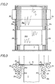
- the exemplary embodiment according to FIGS. 2 and 3 differs from the exemplary embodiment according to FIG. 1 in that the rollers 33a, 33b, 33c for the film strips 34 are held by carriers which are guided into their working position above the conveyor track 1 from above by guides 36 can be lowered.
- tensioning or guide rollers 38 are assigned to the foil strips 34 drawn off from the individual roller pairs 33, by means of which the curtains formed by the foil strips 34 and spanning the conveying path 1 transversely are held in closely adjacent planes.
- These curtains are assigned a single, frame-fixed separating or welding device, which is formed by two welding bars 7, 8 which are adjustable transversely to the conveying direction.
- the operation of this device corresponds to the operation of the device according to Fig. 1 apart from the fact that the pairs 33 of the rollers with the film strips 34 are not adjusted from the side of the conveyor track in their working position, but that these from above along the guides 36 in their Working position can be lowered.
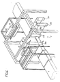
- FIG. 4 of the drawing the device according to Figure 1 is shown axonometrically.
- a film dispenser 40 is also shown, through which a cover film is applied to the cover surfaces of the goods 10 that are to be packaged, which cover film is pulled off a roller 45 and divided into the individual sheets by means of a separating device 46 becomes.
- the goods 10 After the goods 10 have been wrapped with the foils, they are conveyed in a known manner to a subsequent third station, which is formed by a shrinkage channel in which the foil strips are heated to 180 ° C. to 260 ° C. and higher temperatures, depending on their thickness, whereby they are shrunk onto the goods.
- a subsequent third station which is formed by a shrinkage channel in which the foil strips are heated to 180 ° C. to 260 ° C. and higher temperatures, depending on their thickness, whereby they are shrunk onto the goods.
Landscapes
- Engineering & Computer Science (AREA)
- Mechanical Engineering (AREA)
- Basic Packing Technique (AREA)
- Laminated Bodies (AREA)
- Wrappers (AREA)
- Pharmaceuticals Containing Other Organic And Inorganic Compounds (AREA)
- Saccharide Compounds (AREA)
- Nitrogen Condensed Heterocyclic Rings (AREA)
- Containers And Plastic Fillers For Packaging (AREA)
Claims (4)
Applications Claiming Priority (2)
| Application Number | Priority Date | Filing Date | Title |
|---|---|---|---|
| AT3806/84 | 1984-11-30 | ||
| AT0380684A AT387758B (de) | 1984-11-30 | 1984-11-30 | Vorrichtung zum verpacken eines insbesondere von einer palette gehalterten gutstapels mittels einerschrumpffolie |
Publications (2)
| Publication Number | Publication Date |
|---|---|
| EP0183676A1 EP0183676A1 (fr) | 1986-06-04 |
| EP0183676B1 true EP0183676B1 (fr) | 1988-07-27 |
Family
ID=3555694
Family Applications (1)
| Application Number | Title | Priority Date | Filing Date |
|---|---|---|---|
| EP85890281A Expired EP0183676B1 (fr) | 1984-11-30 | 1985-11-13 | Dispositif pour emballer des objets dans une feuille thermorétractable |
Country Status (4)
| Country | Link |
|---|---|
| EP (1) | EP0183676B1 (fr) |
| AT (2) | AT387758B (fr) |
| DE (1) | DE3563940D1 (fr) |
| FI (1) | FI854559L (fr) |
Cited By (1)
| Publication number | Priority date | Publication date | Assignee | Title |
|---|---|---|---|---|
| US9003744B2 (en) | 2009-05-12 | 2015-04-14 | Msk-Verpackungs-Systeme Gmbh | Apparatus for packaging an object in film |
Families Citing this family (12)
| Publication number | Priority date | Publication date | Assignee | Title |
|---|---|---|---|---|
| DE29515605U1 (de) * | 1995-09-30 | 1995-12-14 | Colsman & Kirschner GmbH & Co KG, 45277 Essen | Verpackungsautomat mit automatischem Wechsel des Verpackungsmaterials |
| DE29902910U1 (de) | 1999-02-19 | 2000-03-30 | MSK-Verpackungs-Systeme Gesellschaft mit beschränkter Haftung, 47533 Kleve | Vorrichtung zum Banderolieren einer Packguteinheit mit einer Schrumpffolienbanderole |
| ES2208027B1 (es) * | 2001-11-07 | 2005-04-16 | Construcciones Metalicas Jose Barberan, S.A. | Maquina modular para embalaje automatico con laminas de plastico. |
| ITBO20020232A1 (it) | 2002-04-24 | 2003-10-24 | Aetna Group Spa | Apparecchiature per la fasciatura di gruppi di prodotti pallettizzati |
| ITMC20040141A1 (it) * | 2004-11-29 | 2005-02-28 | Erregi Di Giunti Renzo | Macchina perfezionata per l'imballaggio automatico di prodotti in genere con nastri di incarto. |
| FR2948922B1 (fr) * | 2009-08-04 | 2011-10-07 | Techman Mecanisation | Installation d'emballage comprenant au moins deux modules distincts dont un au moins est mobile par rapport a une direction de convoyage des produits a emballer |
| DE102009050260A1 (de) * | 2009-10-21 | 2011-05-12 | Dücker Automation GmbH | Vorrichtung zum Umhüllen von gestapelten Gütern mit einer Folie |
| IT1400259B1 (it) | 2010-05-25 | 2013-05-24 | Messersi Packaging Srl | Impianto, metodo e stazione per l'avvolgimento laterale di prodotti mediante film plastico. |
| ITMI20100956A1 (it) * | 2010-05-27 | 2011-11-28 | Messersi Packaging Srl | Impianto per l'avvolgimento laterale di prodotti mediante film plastico. |
| EP2392514A1 (fr) | 2010-05-27 | 2011-12-07 | Messersi' Packaging S.R.L. | Machine pour l'emballage latéral de produits avec un film plastique |
| DE102017116458B3 (de) | 2017-07-21 | 2018-08-30 | Valerio Schwucht | Vorrichtung und Verfahren zum Verpacken gestapelter länglicher Gegenstände sowie Verwendung einer derartigen Vorrichtung |
| IT202200009770A1 (it) * | 2022-05-11 | 2023-11-11 | Meta Srl | “macchina pellicolatrice” |
Family Cites Families (3)
| Publication number | Priority date | Publication date | Assignee | Title |
|---|---|---|---|---|
| US3640048A (en) * | 1968-10-07 | 1972-02-08 | Weldotron Corp | Method and apparatus for a pallet load |
| DE2431319A1 (de) * | 1974-06-29 | 1976-01-15 | Leibfried Gmbh K | Verpackungsmaschine zur schrumpffolienumkleidung von stueckgut |
| DE2506932A1 (de) * | 1975-02-19 | 1976-09-02 | Kallfass Karl Heinz | Verfahren und vorrichtung zum banderolieren von guetern |
-
1984
- 1984-11-30 AT AT0380684A patent/AT387758B/de not_active IP Right Cessation
-
1985
- 1985-11-13 AT AT85890281T patent/ATE35955T1/de not_active IP Right Cessation
- 1985-11-13 DE DE8585890281T patent/DE3563940D1/de not_active Expired
- 1985-11-13 EP EP85890281A patent/EP0183676B1/fr not_active Expired
- 1985-11-19 FI FI854559A patent/FI854559L/fi not_active Application Discontinuation
Cited By (1)
| Publication number | Priority date | Publication date | Assignee | Title |
|---|---|---|---|---|
| US9003744B2 (en) | 2009-05-12 | 2015-04-14 | Msk-Verpackungs-Systeme Gmbh | Apparatus for packaging an object in film |
Also Published As
| Publication number | Publication date |
|---|---|
| FI854559A7 (fi) | 1986-05-31 |
| DE3563940D1 (en) | 1988-09-01 |
| ATE35955T1 (de) | 1988-08-15 |
| FI854559A0 (fi) | 1985-11-19 |
| AT387758B (de) | 1989-03-10 |
| EP0183676A1 (fr) | 1986-06-04 |
| FI854559L (fi) | 1986-05-31 |
| ATA380684A (de) | 1987-09-15 |
Similar Documents
| Publication | Publication Date | Title |
|---|---|---|
| DE1704146C3 (de) | Verfahren und Einrichtung zum kontinuierlichen Herstellen von Beuteln Ausscheidung aus 1248911 | |
| EP0183676B1 (fr) | Dispositif pour emballer des objets dans une feuille thermorétractable | |
| DE2708354C2 (de) | Verfahren zum schrumpfmäßigen Wickeln einer Kunststoff-Folie auf einer Reihe von Gegenständen | |
| DE2245198C3 (de) | Beutelherstellungsmaschine | |
| DE3789113T2 (de) | Packung mit einer banderolenartigen hülle sowie verfahren und anordnung zum herstellen einer derartigen packung. | |
| DE2832365C3 (de) | Vorrichtung zum Fördern und Vereinzeln eines Bandes aus zusammenhängenden Skin-Verpackungen | |
| DE2554395C3 (de) | Vorrichtung zum Herstellen von Stapeln aus Kunststoffbeuteln | |
| EP0803446A2 (fr) | Ensemble d'emballage ainsi qu'un procédé et un dispositif pour le réaliser | |
| EP0399948A1 (fr) | Procédé et appareil pour la fabrication en continu d'emballages | |
| DE2931118A1 (de) | Verfahren zur herstellung von sammelpackungen | |
| CH390776A (de) | Einwickelmaschine für insbesondere prismatische Gegenstände | |
| DE3303956C2 (de) | Vorrichtung zum Umreifen eines quaderförmigen Packgutes | |
| DE3688752T2 (de) | Verfahren und Vorrichtung, um eine Vielzahl von Gegenständen miteinander zu verbinden. | |
| DE1629229B1 (de) | Verfahren und vorrichtung zum verschweissen und trennen von uebereinanderliegenden thermoplastischen schrumpffolien | |
| EP0141351B1 (fr) | Dispositif pour envelopper des paquets dans une feuille étirable | |
| EP0111210A1 (fr) | Dispositif d'enveloppement d'articles avec une feuille en matière plastique ou similaire | |
| EP0001386B1 (fr) | Dispositif d'emballage d'objets au moyen d'une feuille | |
| DE69118048T2 (de) | Vorrichtung und Verfahren zum Herstellen, Befüllen und Siegeln bei gleichzeitigem Verpacken von zwei Artikelströmen | |
| DE4120480A1 (de) | Verfahren und vorrichtung zur bildung eines vielfachpacks sowie vielfachpack | |
| EP3587283B1 (fr) | Machine d'emballage destinée à l'emballage dans la feuille étirable et procédé d'emballage optimisé | |
| DE9205480U1 (de) | Vorrichtung zum Siegeln von Folienbahnen aus thermoplastischem Kunststoff | |
| DE102008020604A1 (de) | Verfahren und Vorrichtung zum Verpacken von portionierten Produkten in einem Einwickler | |
| DE60102170T2 (de) | Vorrichtung und Verfahren zum Verpacken eines Produktes in Folienmaterial | |
| EP0109353A2 (fr) | Procédé de fabrication d'un emballage en matière flexible | |
| DE2750392C2 (fr) |
Legal Events
| Date | Code | Title | Description |
|---|---|---|---|
| PUAI | Public reference made under article 153(3) epc to a published international application that has entered the european phase |
Free format text: ORIGINAL CODE: 0009012 |
|
| 17P | Request for examination filed |
Effective date: 19851113 |
|
| AK | Designated contracting states |
Kind code of ref document: A1 Designated state(s): AT BE CH DE FR GB IT LI NL SE |
|
| 17Q | First examination report despatched |
Effective date: 19870508 |
|
| GRAA | (expected) grant |
Free format text: ORIGINAL CODE: 0009210 |
|
| AK | Designated contracting states |
Kind code of ref document: B1 Designated state(s): AT BE CH DE FR GB IT LI NL SE |
|
| REF | Corresponds to: |
Ref document number: 35955 Country of ref document: AT Date of ref document: 19880815 Kind code of ref document: T |
|
| ITF | It: translation for a ep patent filed | ||
| REF | Corresponds to: |
Ref document number: 3563940 Country of ref document: DE Date of ref document: 19880901 |
|
| RAP2 | Party data changed (patent owner data changed or rights of a patent transferred) |
Owner name: ADOLF REKER MASCHINENFABRIK UND BAGGERBAU GMBH |
|
| GBT | Gb: translation of ep patent filed (gb section 77(6)(a)/1977) | ||
| ET | Fr: translation filed | ||
| PLBE | No opposition filed within time limit |
Free format text: ORIGINAL CODE: 0009261 |
|
| STAA | Information on the status of an ep patent application or granted ep patent |
Free format text: STATUS: NO OPPOSITION FILED WITHIN TIME LIMIT |
|
| 26N | No opposition filed | ||
| BECN | Be: change of holder's name |
Effective date: 19880727 |
|
| ITTA | It: last paid annual fee | ||
| PGFP | Annual fee paid to national office [announced via postgrant information from national office to epo] |
Ref country code: FR Payment date: 19931027 Year of fee payment: 9 |
|
| PGFP | Annual fee paid to national office [announced via postgrant information from national office to epo] |
Ref country code: SE Payment date: 19931028 Year of fee payment: 9 Ref country code: CH Payment date: 19931028 Year of fee payment: 9 Ref country code: BE Payment date: 19931028 Year of fee payment: 9 |
|
| PGFP | Annual fee paid to national office [announced via postgrant information from national office to epo] |
Ref country code: GB Payment date: 19931112 Year of fee payment: 9 |
|
| PGFP | Annual fee paid to national office [announced via postgrant information from national office to epo] |
Ref country code: NL Payment date: 19931130 Year of fee payment: 9 Ref country code: AT Payment date: 19931130 Year of fee payment: 9 |
|
| PG25 | Lapsed in a contracting state [announced via postgrant information from national office to epo] |
Ref country code: GB Effective date: 19941113 Ref country code: AT Effective date: 19941113 |
|
| PG25 | Lapsed in a contracting state [announced via postgrant information from national office to epo] |
Ref country code: SE Effective date: 19941114 |
|
| PG25 | Lapsed in a contracting state [announced via postgrant information from national office to epo] |
Ref country code: LI Effective date: 19941130 Ref country code: CH Effective date: 19941130 Ref country code: BE Effective date: 19941130 |
|
| EAL | Se: european patent in force in sweden |
Ref document number: 85890281.0 |
|
| BERE | Be: lapsed |
Owner name: ADOLF REKER MASCHINENFABRIK UND BAGGERBAU G.M.B.H Effective date: 19941130 |
|
| PG25 | Lapsed in a contracting state [announced via postgrant information from national office to epo] |
Ref country code: NL Effective date: 19950601 |
|
| GBPC | Gb: european patent ceased through non-payment of renewal fee |
Effective date: 19941113 |
|
| NLV4 | Nl: lapsed or anulled due to non-payment of the annual fee | ||
| PG25 | Lapsed in a contracting state [announced via postgrant information from national office to epo] |
Ref country code: FR Effective date: 19950731 |
|
| REG | Reference to a national code |
Ref country code: CH Ref legal event code: PL |
|
| EUG | Se: european patent has lapsed |
Ref document number: 85890281.0 |
|
| REG | Reference to a national code |
Ref country code: FR Ref legal event code: ST |
|
| PGFP | Annual fee paid to national office [announced via postgrant information from national office to epo] |
Ref country code: DE Payment date: 19991102 Year of fee payment: 15 |
|
| PG25 | Lapsed in a contracting state [announced via postgrant information from national office to epo] |
Ref country code: DE Free format text: LAPSE BECAUSE OF NON-PAYMENT OF DUE FEES Effective date: 20010801 |