EP0183771B1 - Circuit de verification d'impulsions de reference adaptable pour commande de moteurs - Google Patents
Circuit de verification d'impulsions de reference adaptable pour commande de moteurs Download PDFInfo
- Publication number
- EP0183771B1 EP0183771B1 EP85902754A EP85902754A EP0183771B1 EP 0183771 B1 EP0183771 B1 EP 0183771B1 EP 85902754 A EP85902754 A EP 85902754A EP 85902754 A EP85902754 A EP 85902754A EP 0183771 B1 EP0183771 B1 EP 0183771B1
- Authority
- EP
- European Patent Office
- Prior art keywords
- pulse
- pulses
- occurrence
- response
- counter
- Prior art date
- Legal status (The legal status is an assumption and is not a legal conclusion. Google has not performed a legal analysis and makes no representation as to the accuracy of the status listed.)
- Expired
Links
Images



Classifications
-
- G—PHYSICS
- G01—MEASURING; TESTING
- G01D—MEASURING NOT SPECIALLY ADAPTED FOR A SPECIFIC VARIABLE; ARRANGEMENTS FOR MEASURING TWO OR MORE VARIABLES NOT COVERED IN A SINGLE OTHER SUBCLASS; TARIFF METERING APPARATUS; MEASURING OR TESTING NOT OTHERWISE PROVIDED FOR
- G01D5/00—Mechanical means for transferring the output of a sensing member; Means for converting the output of a sensing member to another variable where the form or nature of the sensing member does not constrain the means for converting; Transducers not specially adapted for a specific variable
- G01D5/12—Mechanical means for transferring the output of a sensing member; Means for converting the output of a sensing member to another variable where the form or nature of the sensing member does not constrain the means for converting; Transducers not specially adapted for a specific variable using electric or magnetic means
- G01D5/244—Mechanical means for transferring the output of a sensing member; Means for converting the output of a sensing member to another variable where the form or nature of the sensing member does not constrain the means for converting; Transducers not specially adapted for a specific variable using electric or magnetic means influencing characteristics of pulses or pulse trains; generating pulses or pulse trains
- G01D5/245—Mechanical means for transferring the output of a sensing member; Means for converting the output of a sensing member to another variable where the form or nature of the sensing member does not constrain the means for converting; Transducers not specially adapted for a specific variable using electric or magnetic means influencing characteristics of pulses or pulse trains; generating pulses or pulse trains using a variable number of pulses in a train
- G01D5/2454—Encoders incorporating incremental and absolute signals
- G01D5/2455—Encoders incorporating incremental and absolute signals with incremental and absolute tracks on the same encoder
- G01D5/2457—Incremental encoders having reference marks
-
- F—MECHANICAL ENGINEERING; LIGHTING; HEATING; WEAPONS; BLASTING
- F02—COMBUSTION ENGINES; HOT-GAS OR COMBUSTION-PRODUCT ENGINE PLANTS
- F02P—IGNITION, OTHER THAN COMPRESSION IGNITION, FOR INTERNAL-COMBUSTION ENGINES; TESTING OF IGNITION TIMING IN COMPRESSION-IGNITION ENGINES
- F02P7/00—Arrangements of distributors, circuit-makers or -breakers, e.g. of distributor and circuit-breaker combinations or pick-up devices
- F02P7/06—Arrangements of distributors, circuit-makers or -breakers, e.g. of distributor and circuit-breaker combinations or pick-up devices of circuit-makers or -breakers, or pick-up devices adapted to sense particular points of the timing cycle
- F02P7/067—Electromagnetic pick-up devices, e.g. providing induced current in a coil
- F02P7/0675—Electromagnetic pick-up devices, e.g. providing induced current in a coil with variable reluctance, e.g. depending on the shape of a tooth
-
- G—PHYSICS
- G01—MEASURING; TESTING
- G01M—TESTING STATIC OR DYNAMIC BALANCE OF MACHINES OR STRUCTURES; TESTING OF STRUCTURES OR APPARATUS, NOT OTHERWISE PROVIDED FOR
- G01M15/00—Testing of engines
- G01M15/04—Testing internal-combustion engines
- G01M15/06—Testing internal-combustion engines by monitoring positions of pistons or cranks
Definitions
- the present invention is related to the invention described in EP-A-0181379
- the present invention relates generally to the field of reference pulse processing circuitry in which a reference pulse corresponding to the occurrence of a predetermined rotational position of a rotating shaft is received by a circuit and further processed. More particularly, the present invention is related to such a reference pulse circuit which is adaptable for control of an internal combustion engine.
- This reference position pulse is typically utilized to initiate proper sequential engine control and distinguish which one of the engine cyclinders should be receiving fuel and spark ignition at any particular time, whereas the large number of projecting teeth are utilized in determining the amount of fuel to be injected and the precise timing of the fuel injection and occurrence of spark in each engine cyclinder.
- Such systems are well known and include distributorless ignition systems and fuel injection systems such as those shown in U.S. patents 4,104,997, 4,338,813 and 4,338,903, all assigned to the assignee of the present invention.
- Some prior engine control systems utilize one sensor to sense the passage of a large number of closely spaced teeth to provide precise resolution of engine rotation, while an additional separate sensor or the same sensor is utilized to sense either a specially shaped tooth or an extra one of the rotated teeth, a separate reference tooth rotated synchronously with the engine crankshaft.
- an additional separate sensor or the same sensor is utilized to sense either a specially shaped tooth or an extra one of the rotated teeth, a separate reference tooth rotated synchronously with the engine crankshaft.
- the engine crankshaft reference position is indicated by the occurrence of the absence of one of a large number of teeth on a rotating wheel wherein the remaining teeth provide pulses for the accurate angular resolution of engine crankshaft rotation.
- Document EP-A-0020070 describes a circuit for recognising cyclically occurring pulse sequences for engine control.
- the circuit comprises means for producing reference pulses corresponding to the occurrence of predetermined reference rotational positions of a rotating shaft, means for producing a pulse train comprising a plurality of pulse trained pulses which occur between the occurrence of said reference rotational positions of said shaft, and means for receiving both said reference pulses and said pulse train pulses.
- the circuit does not verify the correctness of the occurrence of the reference pulses, which in this prior art document are created in response to detecting the occurrence of a missing pulse in the pulse train pulses.
- An object of the present invention is to provide a reference pulse verification circuit which overcomes the above mentioned deficiencies of the prior systems.
- the means for receiving both the reference pulses and the pulse train pulses includes circuitry for verifying the correctness of the occurrence of the said reference pulses by providing a verified reference pulse in response to each reference pulse which occurs at substantially a predetermined number of pulse train pulses after the occurrence of a preceding reference pulse, whereby spurious reference pulses can be differentiated from true reference pulses.
- the invention provides a reference pulse verification circuit adaptable for use in an engine control system in which engine control is implemented in response to verified reference position pulses which are distinguished from unverified reference position pulses by noting the existence of a predetermined plurality of crankshaft rotational position pulses between the occurrence of each reference position pulse.
- the preferred embodiment of the present invention utilizes a single sensor which senses projecting teeth on a rotating wheel rotated by an engine crankshaft. In response to the absence of one of the rotating teeth, the sensor, in combination with a missing pulse detector, provides a reference pulse signal.
- a verification counter effectively counts each one of the teeth sensed by the senor and counts from zero up to a maximum predetermined count which represents the number of teeth which normally occur between sequential reference positions corresponding to the occurrence of the missing tooth position on the rotating wheel. The counter is reset in response to either the occurrence of this maximum count and/or the occurrence of any missing tooth detection signal.
- a verified reference position pulse is provided in response thereto, and the verified pulse is effectively provided to an engine control circuit which controls various functions such as spark/dwell and/or fuel injection.
- the engine control circuit is enabled, after initial power is applied thereto, in response to the reception of the first verified reference position pulse.
- the present invention avoids having the engine control circuit respond to improper reference position pulses thereby minimizing the possibility of improper engine control due to the attempted implementation of spark or fuel injection operations in the wrong cylinder and/or at the wrong time.
- the present invention is most advantageously utilized when a single sensor is used to provide both the sequence initiating reference position pulses as well as the accurate high-resolution crankshaft position pulses, since in such cases the possibility of providing an erroneous reference position pulse is likely during engine transient conditions such as abrupt acceleration or deceleration.
- verified reference pulses will only occur when a known predetermined count is obtained between two sequential reference pulse detections.
- the resetting of the count of the counter in response to the occurrence of the predetermined maximum count representative of the number of teeth between two proper reference pulse detections, is an additional safety feature of the present invention and prevents the counter from continuing to count past the maximum predetermined count.
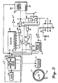
- Figure 1 illustrates an engine control system 10 which includes a wheel 11 having 35 outwardly projecting peripheral teeth 12 uniformaly spaced around the wheel 11 at 10 degree angular increments and including a missing tooth location 13.
- the wheel 11 is rotated about a central axis 14 corresponding to an engine crankshaft.
- the space between each of the teeth 12 represents a ten degree increment of angular rotation of the engine crankshaft with the missing tooth location 13 corresponding to a predetermined engine cylinder reference position of the engine crankshaft. While preferably the teeth 12 are uniformly spaced, this is not necessary for proper operation of the present invention.
- a fixed sensor 15 is positioned adjacent to the wheel 11 and has an active sensor area 16 which senses the passage of the teeth 12 and provides, in response thereto, a corresponding pulse train signal at an output terminal A.
- the terminal A is provided as an input to a buffer, sync and pulse shaper circuit 17 which essentially processes the signal at the terminal A to provide an appropriately delayed and squared up pulse train signal at an output terminal B.
- the pulse train signal at the terminal B is provided as an input to both a missing pulse detector 18 and an engine control circuit 19 wherein the engine control circuit implements such functions as controlling engine spark/dwell and engine fuel injection by providing control signals at an output terminal 20 which is representative of control terminals for engine cylinder spark plugs and/or fuel injectors.
- Such engine control circuits are well known and do not form an essential part of the present invention since they merely respond to crankshaft position pulses to provide the timing signals for implementing various engine controls which control the rotation of the engine crankshaft in accordance with predetermined relationships.
- the signal at terminal B is used by circuit 19 to determine the magnitude and timing of the engine control signals provided at terminal 20, while the circuit 19 responds to reference pulses (at terminal F) to effectively implement the proper sequence of control signals at terminal 20 to the proper engine cylinder apparatus.
- the missing pulse detector 18 responds to the pulse train signal at the terminal B and provides a missing pulse detection output signal at an output terminal C in response to the passage of the missing tooth location 13 past the active sensing area 16.
- the signal at the terminal C represents an unverified reference position pulse corresponding to a predetermined rotational position of the engine crankshaft corresponding to the missing tooth location 13 on the wheel 11.
- the missing pulse detector 18 can comprise any well known missing pulse detector configuration, such as, for example, the configurations discussed in U.S. Patents 4,152,655, 4,311,962 or 4,345,209.
- the missing pulse detector corresponds in general to the apparatus disclosed in the above referred to copending U.S. patent application.
- the present invention is also usable with any type of reference position pulse detector apparatus which provides at the terminal C an indication of the occurrence of a predetermined rotational position of the engine crankshaft.
- reference detectors and apparatus which respond to either split or otherwise unusually shaped teeth are also contemplated by the present invention, as well as the utilization of an additional sensor, separate from the sensor 15, that responds to a separate projection on the rotating wheel 11 to provide a reference detection pulse at the terminal C.
- the pulse train pulses at the terminal B and the reference position pulse signal at the terminal C are both provided as inputs to a reference pulse verification circuit 21 shown dashed in Figure 1.
- the verification circuit 21 comprises a pulse train pulse counter 22 which has a clock input terminal c directly connected to the terminal B.
- the counter 22 serves as a verification counter that effectively directly counts the number of teeth on the rotating wheel 11 by counting the number of pulses produced by the sensor 15 in response to the passage of each of the teeth 12.
- counter 22 can be considered a direct tooth counter since it is incremented one count for each tooth which passes the sensor 15.
- Three count output terminals Q1, Q2 and Q6 of the counter 22 are connected as inputs to an AND gate 23 which provides an output at a terminal E.
- the terminal E is connected as an input to a reset logic and delay circuit 24 which also receives an input via a direct connection to the terminal C and provides an output signal that is connected to a reset terminal R of the counter 22.
- the terminal E is connected as an input to an AND gate 25 which receives an additional input via a direct connection to the terminal C and provides an output at a terminal F that is connected as a sequence initiating input to the engine control circuit 19.
- the terminal F is also connected to a set terminal S of a flip-flop circuit 26 which has its output terminal Q connected to a terminal G that is connected to an enable terminal of the engine control circuit 19.
- a reset terminal R of the flip-flop 26 is connected to a terminal 27 that is connected to ground through the parallel combination of a capacitor 28 and a resistor 29 and is connected to a terminal B+ through a resistor 30 and a rapid discharge diode 31.
- the diode 31 discharges the capacitor 28 in case the power supply voltage drops.
- the terminal B+ is selectively connected via a switch 32 to a source of positive potential comprising a battery 33.
- the engine control circuit 19 and the flip-flop 26 receive operative power via connections to the terminal B+, and it is contemplated that other components of the invention may also receive operative power via such connections.
- the components 22-33 comprise the verification circuit 21.
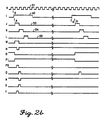
- signal waveform graphs A through G represent the electrical signals produced at the terminals A through G illustrated in Figure 1. All the graphs A-G are drawn with the same horizontal axis time scale with the vertical axes representative of amplitude.
- the graph D in Figure 2 represents the stepped count of the counter 22.
- the signal waveforms shown in the other graphs in Figure 2 are representative of signal waveforms produced by the embodiment shown in Figures 3 and 4 of the present invention, and therefore these signals will be discussed later in conjunction with that embodiment.
- the wheel 11 is rotated by the engine crankshaft such that the 35 teeth 12 pass in proximity to the active sensing area 16 and produce in response thereto a series of tooth pulses which comprise a pulse train signal 40 at terminal A as shown in Figure 2.
- a series of tooth pulses which comprise a pulse train signal 40 at terminal A as shown in Figure 2.
- t o rotation of the engine crankshaft is commenced.
- t1 and t2 a tooth passes by the active sensing area 16 with the result being the creation of tooth pulses at the terminal A.
- the signal at the terminal A indicates that a profile sensor is utilized for the sensor 15, obviously a reluctance sensor and appropriate signal processing circuitry could be utilized to provide substantially equivalent output signal pulses at the terminal A.
- the missing tooth position 13 directly passes by the sensing area 16 and results in the nonoccurrence of a tooth pulse at the terminal A. Subsequently additional tooth pulses are provided in response to the passage of the teeth 12.
- the cycle of the signal 40 repeats after the passage of 35 teeth and the missing tooth location 13.
- the buffer, sync and pulse shaper circuit 17 responds to the signal 40 at terminal A by providing in response thereto a signal 41 comprising short duration pulses synchronized to a high frequency reference oscillator. Such synchronization can be accomplished by many known techniques and is done to assist in implementing short duration known signal delays when they are needed.
- the times at which the pulses of the signal 41 occur substantially corresponds to the tines t1 through t35 in graph A and are so shown in graph B.
- the circuit 17 may also be used to square up the signals at the terminal A and also to delay them, if appropriate, by small finite amounts when this is desired. This will be further discussed in conjunction with the embodiment shown in Figures 3 and 4.
- an equivalent tooth pulse train signal 41 is provided at the terminal B.
- the signal 41 is provided as a timing input to the engine control circuit 19 and also as an input to the missing pulse detector 18.
- the missing pulse detector 18 comprises circuitry which is able to distinguish between the repetitive occurrence of the pulses corresponding to the teeth 12 and the absence of one of these pulses corresponding to the occurrence of the missing tooth location 13.
- the detector 18 provides a missing tooth detection signal 42.
- This is illustrated in Figure 2 graph C as comprising a reference detection pulse commencing substantially at the time t5 and terminating prior to the time t6. It should be noted that preferably the present invention contemplates detecting the occurrence of the missing pulse at the time t3 by providing a detection signal pulse substantially at the time t5. However, even if missing pulse detectors are utilized which provide for an earlier detection of the missing pulse, the present invention still can be utilized.
- the circuitry within the missing pulse detector 18 can be of any conventional design wherein many types of circuit configurations are known for such missing pulse detectors.
- the use of missing pulse detectors in engine control systems generally saves the expense of an additional sensor to provide a reference pulse.
- such missing pulse detectors are subject to providing erroneous pulse detection outputs during abrupt engine transient conditions such as acceleration and/or deceleration.
- the present invention provides therefore for verifying the accuracy of the output of the missing pulse detector 18 and insuring that only verified missing pulse detections are allowed to determine the operation of the engine control circuit 19.
- the present invention can also be used to verify the correctness of any reference pulse detection apparatus wherein a known plurality of timing (tooth) pulses occur between reference pulses.
- the counter 22 is incremented in response to each tooth pulse provided at the terminal B. This is indicated by the staircase step waveform 43 shown in Figure 2 graph D. It is assumed that at the start time of t o the counter 22 is reset to a zero count by additional circuitry which is not shown in Figure 1, wherein this can comprise a transient reset circuit responsive to the closure of the switch 32 that provides operative B+ power to the engine control circuit 19 and flip-flop 26.
- the waveform 43 maintains a fixed count of 2 until substantially the time t4 when it is again upward incremented to 3 and then, after a very short duration upward increment to a count of 4, the counter 22 is reset in response to the occurrence of the missing pulse detection which occurs substantially at the time t5 and results in resetting counter 22 slightly thereafter due to a delay implemented by circuit 24.
- This reset results in setting the counter 22 to a predetermined count of zero from which it is again upward incremented in response to the tooth pulse at t6 and the other pulses comprising the pulse train signal 41 at the terminal B.
- the count of the counter 22 is upward incremented until it achieves a maximum predetermined count of 35 just after the next occurrence of t5.
- the missing pulse detector 18 will again produce a missing pulse detection pulse at the terminal C.
- the AND gate 23 will provide a high output signal pulse 44 at the terminal E.
- a missing pulse detection is provided by the detector 18, a similar high logic state will be provided at the terminal C as part of the signal 42.
- the coincidence of high logic states at the terminals E and C result in the AND gate 25 providing a high logic pulse 45 at the terminal F which is therefore representative of a verified missing pulse detection. This is because it is known that between two proper missing pulse detection pulses provided by the detector 18, a total of 35 pulse train tooth pulses must be provided as inputs to the counter 22.
- the AND gate 25 effectively passes the unverified reference pulse 44 at terminal C to provide the verified reference pulse 45 at terminal F in response to the occurrence of the unverified pulse corresponding to the time occurrence of a final count of 35 of the counter 22.
- the reset logic and delay circuit 24 responds to either the providing of a high missing pulse detection signal 42 at the terminal C or the attainment of a maximum count of the counter 22 indicated by the high logic signal 44 at the terminal E by, in response to either and/or both of these outputs, producing a reset of the counter 22 to a zero count.
- the reset and logic delay circuit 24 besides effectively OR-ing the signals at the terminals E and C to provide a reset signal to the counter 22, also provides an appropriate delay function to these signals such that this resetting will occur after the attainment of a count of 35 causing a high pulse in signal 44 at the terminal E and/or after the occurrence of a proper missing pulse detection at the terminal C.
- the components 26 through 33 in the Figure 1 embodiment illustrate that the present invention provides for enabling the engine control circuit 19 in response to the first verified missing pulse detection which occurs after the application of power to the engine control circuit 19.
- operative power is provided at the terminal B+ to at least both the engine control circuit 19 and the flip-flop 26.
- a low signal will still be provided at the terminal 27 due to the action of the capacitor 28.
- This low signal maintains the flip-flop 26 Q output reset at a low output state until the capacitor 28 charges up, at which time the flip-flop 26 can be set.
- a low state at the terminal G which is directly connected to the flip-flop Q terminal, does not permit the enablement of the engine control circuit 19.
- This enablement function can be readily implemented by merely blocking the production of any control voltages at the output 20 by the engine control circuit until a high logic signal is provided at the enablement terminal of the circuit 19. As the capacitor 28 charges up, a high signal is provided at terminal 27 which will therefore allow the flip-flop 26 to be set.
- the signal at terminal 27 can be considered a power up transient signal.
- the flip-flop 26 In response to the first verified missing pulse detection signal provided at a terminal F, the flip-flop 26 is set to a high state as shown in Figure 2, graph G which thereby enables the engine control circuit 19 to provide suitable control signals at the output terminal 20.
- the present invention has provided for enabling the engine control circuit 19 in response to the occurrence of the first verified reference pulse detection after the power-up transient signal provided at the terminal 27 which resulted in maintaining the flip-flop 26 reset until some time after the initial application of power to the control circuit 19.
- the buffer, sync and pulse shaper circuit 17 is shown as comprising a very high frequency clock 50 which provides a constant frequency one megahertz output signal 51 at a terminal H which is provided as an input to a pulse shaper and sync delay circuit 52 that also receives, as an input, the signal 40 at the terminal A.
- the circuit 52 essentially provides three synchronized but slightly delayed output pulse signals 53, 54 and 55 at terminals J, K, and L, respectively, in response to each tooth pulse provided as part of the signal 40. This is illustrated in the Figure 2 waveforms H through L which depict the signals present at the terminals identified by the same letters wherein the signal 40 at the terminal A is represented by the waveform shown in Figure 2 graph I.
- Essentialy the circuit 52 which is shown in substantially more detail in Figure 4, synchronizes tooth pulses of the signal 40 to the high frequency clock signal 51 provided at the terminal H.
- the synchronized signal 53 provided at the terminal J comprises a pulse which starts at the next clock pulse positive transition which occurs after the time t5, and this pulse at the terminal J terminates at the next subsequent positive clock pulse transition.
- the signal 54 at the terminal K is identical to the signal at the terminal J, but delayed by one clock pulse period, and a similar statement applies to the signal 55 at the terminal L being delayed with respect to the signal 54 at the terminal K by one clock pulse period. In this manner three short duration slightly delayed pulses are provided for each tooth pulse created by the sensor 15 and the delay periods between these pulses can be utilized to insure the proper resetting of the verification counter 22.
- the terminal J in Figure 3 is connected as an input to the clock terminal of the counter 22 thus resulting in the clock 22 being incremented in synchronism with the high frequency clock signal 51 provided by the clock 50 and being incremented ahead of the occurrence of pulses on the corresponding but delayed and synchronized signals 54 and 55.
- the signal 53 is also provided as an input to the missing tooth detector 18 which preferably responds to this signal to provide a missing tooth reference pulse detection after the occurrence of the missing tooth position 13 and, preferably, after the occurrence of one additional tooth pulse and substantially coincident with the occurrence of the next additional tooth pulse at t5.
- the configuration shown in Figure 4 for the pulse shaper and synchronizing delay circuit 52 is merely a typical configuration for a circuit which receives the signal 40 at the terminal A and provides synchronized but delayed output pulses in response thereto at the terminals J, K, and L as shown in the graphs J, K, and L in Figure 2.
- three output states Q1, Q2 and Q6 of the counter 22 are connected as inputs to a NAND gate 56 which also receives an inverted clock pulse signal input from the terminal H via an inverter stage 57.
- the logic provided by just the ANDing of the counter 22 states Q1, Q2 and Q6 is shown in graph M, and the output of the NAND gate 56 is provided at a terminal 58 and is shown in graph N and actually represents the inverted signal at the terminal E.
- the terminal 58 is connected as an input to a NOR gate 59 which receives an additional input shown in graph O from the terminal C via an inverter gate 60 and provides as its output the signal at the terminal F shown in graph T.
- the signal in graph O represents an inverted missing pulse detection signal, and is the inverse of the signal 42 shown in graph C.
- the output of the inverter 60 is also provided as input to a NAND gate 61 which also receives an input via a connection to the terminal 58 and provides an output shown in either graphs P1 or P2 as an input to a NAND gate 62.
- Graph P1 illustrates the output of gate 61 if a missing pulse has been detected, as it normally should be at the time t5, and graph P2 shows the output of gate 61 if a missing pulse was not detected. It should be noted that in the first case the gate 61 output goes high because of a missing pulse detect whereas in the second case the gate 61 goes high because a counter maximum count was achieved. In any event, the end result will be the resetting of the counter due to gate 61 going high.
- the terminal K is connected through an inverter 63 as an input to a NOR gate 64 which receives an additional input via a direct connection to the clock terminal H and provides an output shown in graph Q as an input to the NAND gate 62.
- the output of the NAND gate 62 is shown in graph R and is connected as an input to a NAND gate 65 which receives an additional input via a direct connection to the terminal 27 and provides a reset output shown in graph S directly to the reset terminal of the counter 22.
- the flip-flop 26 has now been illustrated as comprising a D-type flip-flop with the terminal F being connected to the clock terminal of the flip-flop and the not set ( S ) and data (D) terminals being connected to the B+ terminal.
- the terminal 27 by virtue of its connection as an input to the NAND gate 65, results in the resetting of the counter 22 after the application of B+ power and maintains the counter 22 reset until some predetermined time after the initial power up transient.
- a reference pulse verification circuit has been provided in which the occurrence of an engine crankshaft reference position pulse has been verified by providing a verified reference pulse only in response to the coincidence of a reference position pulse with a predetermined incremented count of a counter wherein it is known that between proper reference position pulse occurrences a predetermined number of tooth pulses will be provided to a counter for counting thereby. While I have shown and described specific embodients of this invention, further modifications and improvements will occur to those skilled in the art. Such modifications, as previously noted, could comprise the utilizing of other types of reference position detectors rather than the missing pulse detector 18 contemplated by the present invention. Such other types of detectors could utilize a sensor in addition to the sensor 15 and could function by sensing a projection in addition to the projecting teeth 12.
- the present invention preferably will utilize only a single sensor and this provides a substantial advantage when the output of this single sensor is utilized not only to provide accurate angular resolution pulses for the engine crankshaft, but also to provide engine rotational reference position pulses for the proper sequencing of an engine control circuit. All such modifications which retain the basic underlying principles disclosed and claimed herein are within the scope of this invention.
Landscapes
- Engineering & Computer Science (AREA)
- Physics & Mathematics (AREA)
- Chemical & Material Sciences (AREA)
- Combustion & Propulsion (AREA)
- General Physics & Mathematics (AREA)
- Electromagnetism (AREA)
- Mechanical Engineering (AREA)
- General Engineering & Computer Science (AREA)
- Combined Controls Of Internal Combustion Engines (AREA)
- Transmission And Conversion Of Sensor Element Output (AREA)
- Measurement Of Length, Angles, Or The Like Using Electric Or Magnetic Means (AREA)
- Testing Of Engines (AREA)
Abstract
Claims (11)
- Circuit de vérification d'impulsion de référence comportant :
des moyens (11 à 18) destinés à produire des impulsions de référence (42) correspondant à l'apparition de positions de rotation de référence prédéterminées d'un arbre rotatif (14),
des moyens (11 à 17) destinés à produire un train d'impulsions (41) comportant plusieurs impulsions de train d'impulsions qui apparaissent entre l'apparition des dites positions de rotation de référence du dit arbre,
des moyens (21) destinés à recevoir à la fois les dites impulsions de référence (42) et les dites impulsions de train d'impulsions (41) et caractérisé par
les dits moyens (21) comprenant un circuit destiné à vérifier la validité de l'apparition des dites impulsions de référence (42) en prévoyant une impulsion de référence vérifiée (45) en réponse à chaque impulsion de référence (42) qui apparait substantiellement à un nombre prédéterminé d'impulsions du train d'impulsions après l'apparition d'une impulsion de référence précédente, des impulsions de référence parasites pouvant ainsi être différentiées des impulsions de référence vraies. - Circuit de vérification d'impulsion de référence selon la revendication 1, dans lequel les dits moyens de train d'impulsions comprennent un capteur positionné de façon à délivrer un signal de sortie comportant les dites impulsions de train d'impulsions en réponse au passage d'une pluralité de projections espacées positionnées sur une roue entraînée en rotation par le dit arbre, chaque impulsion du train d'impulsions correspondant aux positions de rotation prédéterminée du dit arbre.
- Circuit de vérification d'impulsion de référence selon la revendication 2, dans lequel les dits moyens d'impulsions de référence comportent des moyens destinés à recevoir le signal de sortie du dit capteur et délivrer le dit signal d'impulsion de référence en réponse à la détection de l'absence d'au moins une des dites projections espacées.
- Circuit de vérification d'impulsion de référence selon la revendication 1, dans lequel les dits moyens de vérification comprennent des moyens de compteur destinés à compter le nombre des dites impulsions de train d'impulsions.
- Circuit de vérification d'impulsion de référence selon la revendication 4, dans lequel les dits moyens de compteur comprennent des moyens de présélection destinés à présélectionner de manière effective le compte du dit compteur à un compte initial prédéterminé après et en réponse à l'apparition de chacune des dites impulsions de référence.
- Circuit de vérification d'impulsion de référence selon la revendication 5, dans lequel les dits moyens de vérification comprennent des moyens destinés à faire passer de manière effective la dite impulsion de référence afin de délivrer une des dites impulsions de référence vérifiées en réponse à l'apparition de la dite impulsion de référence correspondant à l'apparition du compte final prédéterminé du dit compteur.
- Circuit de vérification d'impulsion de référence selon la revendication 6, dans lequel les dits moyens de présélection comprennent des moyens destinés à présélectionner également le compte du dit compteur en réponse au dit compteur terminant au moins le dit compte final prédéterminé.
- Circuit de vérification d'impulsion de référence selon la revendication 1, qui comprend des moyens de commande destinés à recevoir les dites impulsions de référence vérifiées et mettre en oeuvre la commande d'un moteur en fonction des relations prédéterminées en réponse à cela, la dite commande de moteur affectant la rotation du dit arbre.
- Circuit de vérification d'impulsion de référence selon la revendication 8, dans lequel les dits moyens de commande reçoivent également les dites impulsions de train d'impulsions et délivrent la dite commande de moteur en réponse à cela.
- Circuit de vérification d'impulsion de référence selon la revendication 8, qui comporte des moyens de validation destinés à valider les dits moyens de commande pour mettre en ouvre la dite commande moteur en réponse à l'apparition des dites impulsions de référence vérifiées.
- Circuit de vérification d'impulsion de référence selon la revendication 10, dans lequel les dits moyens de validation comprennent des moyens destinés à valider les dits moyens de commande en réponse à l'apparition de la première des dites impulsions de référence vérifiées qui apparait après un signal transitoire de mise en route représentatif de l'application de tension sur au moins l'un des dits moyens de commande et moyens de vérification.
Applications Claiming Priority (2)
| Application Number | Priority Date | Filing Date | Title |
|---|---|---|---|
| US613653 | 1984-05-23 | ||
| US06/613,653 US4553426A (en) | 1984-05-23 | 1984-05-23 | Reference pulse verification circuit adaptable for engine control |
Publications (3)
| Publication Number | Publication Date |
|---|---|
| EP0183771A1 EP0183771A1 (fr) | 1986-06-11 |
| EP0183771A4 EP0183771A4 (fr) | 1988-06-13 |
| EP0183771B1 true EP0183771B1 (fr) | 1991-07-03 |
Family
ID=24458158
Family Applications (1)
| Application Number | Title | Priority Date | Filing Date |
|---|---|---|---|
| EP85902754A Expired EP0183771B1 (fr) | 1984-05-23 | 1985-05-06 | Circuit de verification d'impulsions de reference adaptable pour commande de moteurs |
Country Status (5)
| Country | Link |
|---|---|
| US (1) | US4553426A (fr) |
| EP (1) | EP0183771B1 (fr) |
| JP (1) | JPS61500811A (fr) |
| DE (1) | DE3583380D1 (fr) |
| WO (1) | WO1985005445A1 (fr) |
Families Citing this family (42)
| Publication number | Priority date | Publication date | Assignee | Title |
|---|---|---|---|---|
| US4607523A (en) * | 1984-09-20 | 1986-08-26 | Fujitsu Ten Limited | Crank angle detecting apparatus for an internal combustion engine |
| JPS61193011A (ja) * | 1985-02-21 | 1986-08-27 | Honda Motor Co Ltd | 内燃エンジンの始動開始直後のクランク角度基準位置検出方法 |
| USRE34183E (en) * | 1986-02-05 | 1993-02-23 | Electromotive Inc. | Ignition control system for internal combustion engines with simplified crankshaft sensing and improved coil charging |
| US4787354A (en) * | 1986-02-05 | 1988-11-29 | Electromotive, Inc. | Ignition control system for internal combustion engines with simplified crankshaft sensing and improved coil charging |
| DE3634587A1 (de) * | 1986-10-10 | 1988-04-14 | Bosch Gmbh Robert | Zuendsystem fuer verbrennungsmotoren |
| JPH07104689B2 (ja) * | 1986-11-07 | 1995-11-13 | フアナツク株式会社 | パルスエンコ−ダ |
| US5041979A (en) * | 1987-04-08 | 1991-08-20 | Motorola, Inc. | Bounded synchronous angle counter |
| US4931940A (en) * | 1987-06-05 | 1990-06-05 | Honda Giken Kogyo Kabushiki Kaisha | Rotational position detector for controlling an internal combustion engine |
| US4843580A (en) * | 1987-06-24 | 1989-06-27 | Delco Electronics Corporation | Noise immune crankshaft pulse position developing apparatus |
| FR2618576B1 (fr) * | 1987-07-24 | 1990-12-28 | Bendix Electronics Sa | Dispositif de declenchement d'evenement en phase avec une position angulaire d'un organe rotatif et son application |
| US4941445A (en) * | 1988-05-16 | 1990-07-17 | Motorola, Inc. | Electronic position sensor assembly and engine control system |
| EP0342376B1 (fr) | 1988-05-16 | 1996-02-14 | Motorola, Inc. | Capteur électronique de position associé à un système de commande |
| US4962470A (en) * | 1988-08-01 | 1990-10-09 | Delco Electronics Corporation | Crankshaft pulse position developing apparatus having a synchronous digital filter |
| US4893244A (en) * | 1988-08-29 | 1990-01-09 | General Motors Corporation | Predictive spark timing method |
| JPH0715279B2 (ja) * | 1988-10-14 | 1995-02-22 | 三菱電機株式会社 | 点火時期制御装置 |
| US4936277A (en) * | 1988-12-19 | 1990-06-26 | Motorola, Inc. | System for monitoring and/or controlling multiple cylinder engine performance |
| DE3924843A1 (de) * | 1989-07-27 | 1991-02-07 | Prufrex Elektro App | Verfahren und anordnung mit induktivem drehgeber zur steuerung, insbesondere des zuendzeitpunkts von brennkraftmaschinen |
| US5156125A (en) * | 1990-10-11 | 1992-10-20 | Mitsubishi Denki Kabushiki Kaisha | Engine control apparatus |
| US5184080A (en) * | 1990-11-02 | 1993-02-02 | Outboard Marine Corporation | Test apparatus for opto-electronic time based generator of an ignition system |
| US5184590A (en) * | 1991-02-12 | 1993-02-09 | Mitsubishi Denki Kabushiki Kaisha | Engine timing control apparatus |
| US5165271A (en) * | 1991-03-29 | 1992-11-24 | Cummins Electronics | Single sensor apparatus and method for determining engine speed and position |
| US5088465A (en) * | 1991-05-24 | 1992-02-18 | Ford Motor Company | Fast start fueling for fuel injected spark ignition engine |
| US5161175A (en) * | 1991-05-28 | 1992-11-03 | Motorola, Inc. | Circuit and method of detecting an invalid clock signal |
| DE4133570C1 (fr) * | 1991-10-10 | 1992-12-24 | Robert Bosch Gmbh, 7000 Stuttgart, De | |
| US5481909A (en) * | 1994-03-07 | 1996-01-09 | Motorola, Inc. | Apparatus and method for measuring reciprocating engine performance dependent on positional behavior of a member driven by engine torque |
| US5764524A (en) * | 1996-02-12 | 1998-06-09 | Snap-On Technologies, Inc. | Method and apparatus for detection of missing pulses from a repetitive pulse train |
| DE19820817C2 (de) * | 1998-05-09 | 2001-09-13 | Bosch Gmbh Robert | Einrichtung zur Regelung einer mehrzylindrigen Brennkraftmaschine |
| GB0009860D0 (en) | 2000-04-25 | 2000-06-07 | Perkins Engines Co Ltd | Timing ring |
| AT4801U3 (de) * | 2001-08-22 | 2002-06-25 | Avl List Gmbh | Verfahren und vorrichtung zum bereitstellen eines kurbelwinkelbasierten signalverlaufes |
| DE10201430A1 (de) * | 2002-01-16 | 2003-08-14 | Siemens Ag | Verfahren zur Drehrichtungsumkehr bei Zweitaktmotoren |
| FR2860069B1 (fr) * | 2003-09-19 | 2005-12-02 | Siemens Vdo Automotive | Procede de detection d'une reference sur un disque dente associe a un dispositif de determination de position angulaire d'une piece tournante |
| GB0608973D0 (en) * | 2006-05-06 | 2006-06-14 | Gunton Bruce S | Aperture closure member control arrangements |
| FR2910543B1 (fr) * | 2006-12-22 | 2009-03-20 | Inst Francais Du Petrole | Methode d'estimation des durees des dents d'une cible moteur |
| ITTV20070065A1 (it) * | 2007-04-17 | 2008-10-18 | Nice Spa | Azionamento con migliorato sensore rotazionale |
| CN101806670B (zh) * | 2010-04-06 | 2012-06-27 | 苏州大学 | 锻压机缺件检测方法和装置 |
| FR2978542B1 (fr) * | 2011-07-28 | 2013-09-06 | Continental Automotive France | Procede de determination d'une information representative de la position d'une dent reelle d'une cible dentee solidaire en rotation d'un arbre d'un moteur a combustion interne et dispositif associe |
| US9079261B2 (en) | 2012-05-02 | 2015-07-14 | Hamilton Sundstrand Corporation | Detecting a relative shaft position on geared shafts |
| US9103847B2 (en) * | 2012-08-01 | 2015-08-11 | Freescale Semiconductor, Inc. | Variable reluctance sensor interface with integration based arming threshold |
| JP2014047747A (ja) * | 2012-09-03 | 2014-03-17 | Suzuki Motor Corp | エンジン制御装置 |
| FR3084154B1 (fr) | 2018-07-20 | 2020-09-11 | Continental Automotive France | Determination de la position angulaire d'une cible dentee solidaire en rotation d'un arbre d'un moteur a combustion interne |
| FR3114400A1 (fr) * | 2020-09-24 | 2022-03-25 | Vitesco Technologies | Détermination de la position angulaire au moyen d’un capteur arbre à cames X+1 dents |
| CN112963245B (zh) * | 2021-03-16 | 2021-12-21 | 潍柴动力股份有限公司 | 一种发动机转速传感器空气间隙控制装置与控制方法 |
Family Cites Families (23)
| Publication number | Priority date | Publication date | Assignee | Title |
|---|---|---|---|---|
| US29810A (en) * | 1860-08-28 | Water-wheel | ||
| US3572103A (en) | 1967-01-06 | 1971-03-23 | Marquette Corp | Analyzer for multi-cylinder internal combustion engine having means for identifying individual cylinders |
| US3652943A (en) * | 1970-05-04 | 1972-03-28 | Honeywell Inc | Apparatus including delay means for detecting the absence of information in a stream of bits |
| JPS5141953B2 (fr) * | 1972-03-03 | 1976-11-12 | ||
| US4091425A (en) * | 1972-10-24 | 1978-05-23 | Mca Technology, Inc. | Isolated non-consecutive missing half cycle compensator |
| US3795867A (en) * | 1973-04-02 | 1974-03-05 | Gte Automatic Electric Lab Inc | Pulse detection arrangement |
| DE2357061C2 (de) * | 1973-11-15 | 1985-02-14 | Robert Bosch Gmbh, 7000 Stuttgart | Einrichtung zur Abgabe von gleichmäßigen Impulsen bei bestimmten Winkelstellungen einer drehbaren Welle und zur Bildung von wenigstens einem Bezugssignal |
| IT1043269B (it) * | 1975-10-10 | 1980-02-20 | Magneti Marelli Spa | Sistema di inviduazione di una pluralita di posizioni angolaridi un organo rotante |
| US4015466A (en) * | 1976-05-07 | 1977-04-05 | United Technologies Corporation | Determination of number of teeth on an internal combustion engine flywheel |
| DE2644646C2 (de) * | 1976-10-02 | 1983-04-07 | Robert Bosch Gmbh, 7000 Stuttgart | Vorrichtung zur Erkennung eines oder mehrerer fehlender Impulse in einer sonst regelmäßigen Impulsfolge |
| JPS5826339Y2 (ja) * | 1977-07-20 | 1983-06-07 | 株式会社デンソー | 回転基準位置検出装置 |
| JPS5436961A (en) * | 1977-08-29 | 1979-03-19 | Nissan Motor | Angleeoffrotation detector |
| US4142159A (en) * | 1977-11-07 | 1979-02-27 | The United States Of America As Represented By The United States Department Of Energy | Missing pulse detector for a variable frequency source |
| DE3066935D1 (en) * | 1979-05-25 | 1984-04-19 | Lucas Ind Plc | Circuit for distinguishing specific pulse patterns in a pulse train |
| EP0020071B1 (fr) * | 1979-05-25 | 1983-10-12 | LUCAS INDUSTRIES public limited company | Détecteur d'impulsions manquantes |
| US4358828A (en) * | 1979-06-11 | 1982-11-09 | Cummins Engine Company, Inc. | Engine speed measuring system |
| US4311962A (en) * | 1979-09-04 | 1982-01-19 | The Bendix Corporation | Variable frequency missing pulse detector |
| DE2947412A1 (de) * | 1979-11-24 | 1981-06-04 | Robert Bosch Gmbh, 7000 Stuttgart | Drehzahl- oder drehwinkelgeber und zugehoerige auswerteschaltung |
| US4378004A (en) * | 1981-02-23 | 1983-03-29 | Motorola Inc. | Engine control system with cylinder identification apparatus |
| JPS585469A (ja) * | 1981-06-30 | 1983-01-12 | Nec Home Electronics Ltd | エンジン点火装置 |
| US4380980A (en) * | 1981-10-13 | 1983-04-26 | Motorola Inc. | Ignition spark timing circuit |
| US4387684A (en) * | 1981-10-13 | 1983-06-14 | Motorola Inc. | Ignition advance circuit with sensor inputs |
| US4385605A (en) * | 1981-10-13 | 1983-05-31 | Motorola Inc. | Electronic ignition input logic |
-
1984
- 1984-05-23 US US06/613,653 patent/US4553426A/en not_active Expired - Lifetime
-
1985
- 1985-05-06 WO PCT/US1985/000822 patent/WO1985005445A1/fr not_active Ceased
- 1985-05-06 JP JP60502265A patent/JPS61500811A/ja active Pending
- 1985-05-06 DE DE8585902754T patent/DE3583380D1/de not_active Expired - Lifetime
- 1985-05-06 EP EP85902754A patent/EP0183771B1/fr not_active Expired
Also Published As
| Publication number | Publication date |
|---|---|
| JPS61500811A (ja) | 1986-04-24 |
| EP0183771A4 (fr) | 1988-06-13 |
| DE3583380D1 (de) | 1991-08-08 |
| US4553426A (en) | 1985-11-19 |
| WO1985005445A1 (fr) | 1985-12-05 |
| EP0183771A1 (fr) | 1986-06-11 |
Similar Documents
| Publication | Publication Date | Title |
|---|---|---|
| EP0183771B1 (fr) | Circuit de verification d'impulsions de reference adaptable pour commande de moteurs | |
| US4941445A (en) | Electronic position sensor assembly and engine control system | |
| US4797827A (en) | Angular position detector | |
| US4715009A (en) | Device for determining angular position of a rotating part | |
| EP0181379B1 (fr) | Detecteur d'impulsions absentes ou supplementaires | |
| US4181884A (en) | Rotational position detection device using a reference mark and two sensors spaced integer times apart | |
| US3957023A (en) | Pressure responsive engine ignition control system | |
| US4338813A (en) | Electronic engine synchronization and timing apparatus | |
| EP0591283B1 (fr) | Procede pour determiner la position en rotation d'un vilebrequin d'un moteur a combustion interne | |
| US5079945A (en) | Crankshaft direction of rotation detecting apparatus | |
| EP0404763B1 (fr) | Appareil de reconnaissance de cylindre pour systeme d'allumage sans distributeur | |
| US4284052A (en) | Sequential injector timing apparatus | |
| US5410253A (en) | Method of indicating combustion in an internal combustion engine | |
| US5701876A (en) | Misfire detecting apparatus for internal combustion engine | |
| JP3506116B2 (ja) | エンジン制御装置 | |
| US4726347A (en) | Electronic ignition signal distributor for automobile engine | |
| US4265210A (en) | Electric control apparatus for internal combustion engines | |
| JPH07117036B2 (ja) | 点火制御装置 | |
| US4416235A (en) | Ignition timing control apparatus for internal combustion engine | |
| US4372273A (en) | Quadrature trigger system for sequential fuel injection | |
| IE43974B1 (en) | Apparatus for monitoring an electrical ignition internal combustion engine | |
| EP0342376B1 (fr) | Capteur électronique de position associé à un système de commande | |
| JP3508727B2 (ja) | エンジン制御装置 | |
| JPS60149943A (ja) | 内燃機関の回転位置検出装置 | |
| JP4244484B2 (ja) | エンジンの点火時期制御装置 |
Legal Events
| Date | Code | Title | Description |
|---|---|---|---|
| PUAI | Public reference made under article 153(3) epc to a published international application that has entered the european phase |
Free format text: ORIGINAL CODE: 0009012 |
|
| 17P | Request for examination filed |
Effective date: 19860115 |
|
| AK | Designated contracting states |
Kind code of ref document: A1 Designated state(s): DE FR GB |
|
| A4 | Supplementary search report drawn up and despatched |
Effective date: 19880613 |
|
| 17Q | First examination report despatched |
Effective date: 19900313 |
|
| GRAA | (expected) grant |
Free format text: ORIGINAL CODE: 0009210 |
|
| AK | Designated contracting states |
Kind code of ref document: B1 Designated state(s): DE FR GB |
|
| REF | Corresponds to: |
Ref document number: 3583380 Country of ref document: DE Date of ref document: 19910808 |
|
| ET | Fr: translation filed | ||
| PLBE | No opposition filed within time limit |
Free format text: ORIGINAL CODE: 0009261 |
|
| STAA | Information on the status of an ep patent application or granted ep patent |
Free format text: STATUS: NO OPPOSITION FILED WITHIN TIME LIMIT |
|
| 26N | No opposition filed | ||
| PGFP | Annual fee paid to national office [announced via postgrant information from national office to epo] |
Ref country code: FR Payment date: 19930427 Year of fee payment: 9 |
|
| PGFP | Annual fee paid to national office [announced via postgrant information from national office to epo] |
Ref country code: GB Payment date: 19930429 Year of fee payment: 9 Ref country code: DE Payment date: 19930429 Year of fee payment: 9 |
|
| PG25 | Lapsed in a contracting state [announced via postgrant information from national office to epo] |
Ref country code: GB Effective date: 19940506 |
|
| GBPC | Gb: european patent ceased through non-payment of renewal fee |
Effective date: 19940506 |
|
| PG25 | Lapsed in a contracting state [announced via postgrant information from national office to epo] |
Ref country code: FR Effective date: 19950131 |
|
| PG25 | Lapsed in a contracting state [announced via postgrant information from national office to epo] |
Ref country code: DE Effective date: 19950201 |
|
| REG | Reference to a national code |
Ref country code: FR Ref legal event code: ST |