EP0183874B1 - Outil hydraulique de percussion - Google Patents
Outil hydraulique de percussion Download PDFInfo
- Publication number
- EP0183874B1 EP0183874B1 EP84114947A EP84114947A EP0183874B1 EP 0183874 B1 EP0183874 B1 EP 0183874B1 EP 84114947 A EP84114947 A EP 84114947A EP 84114947 A EP84114947 A EP 84114947A EP 0183874 B1 EP0183874 B1 EP 0183874B1
- Authority
- EP
- European Patent Office
- Prior art keywords
- piston
- cylinder
- piston rod
- housing
- bore
- Prior art date
- Legal status (The legal status is an assumption and is not a legal conclusion. Google has not performed a legal analysis and makes no representation as to the accuracy of the status listed.)
- Expired
Links
- 238000009527 percussion Methods 0.000 title description 4
- 239000007787 solid Substances 0.000 description 2
- 238000010276 construction Methods 0.000 description 1
- 230000000694 effects Effects 0.000 description 1
- 230000017525 heat dissipation Effects 0.000 description 1
- 230000001976 improved effect Effects 0.000 description 1
- 239000012528 membrane Substances 0.000 description 1
- 230000000149 penetrating effect Effects 0.000 description 1
Images

Classifications
-
- B—PERFORMING OPERATIONS; TRANSPORTING
- B25—HAND TOOLS; PORTABLE POWER-DRIVEN TOOLS; MANIPULATORS
- B25D—PERCUSSIVE TOOLS
- B25D9/00—Portable percussive tools with fluid-pressure drive, i.e. driven directly by fluids, e.g. having several percussive tool bits operated simultaneously
- B25D9/14—Control devices for the reciprocating piston
- B25D9/16—Valve arrangements therefor
- B25D9/20—Valve arrangements therefor involving a tubular-type slide valve
-
- B—PERFORMING OPERATIONS; TRANSPORTING
- B25—HAND TOOLS; PORTABLE POWER-DRIVEN TOOLS; MANIPULATORS
- B25D—PERCUSSIVE TOOLS
- B25D9/00—Portable percussive tools with fluid-pressure drive, i.e. driven directly by fluids, e.g. having several percussive tool bits operated simultaneously
- B25D9/14—Control devices for the reciprocating piston
- B25D9/145—Control devices for the reciprocating piston for hydraulically actuated hammers having an accumulator
-
- B—PERFORMING OPERATIONS; TRANSPORTING
- B25—HAND TOOLS; PORTABLE POWER-DRIVEN TOOLS; MANIPULATORS
- B25D—PERCUSSIVE TOOLS
- B25D2209/00—Details of portable percussive tools with fluid-pressure drive, i.e. driven directly by fluids, e.g. having several percussive tool bits operated simultaneously
- B25D2209/002—Pressure accumulators
-
- B—PERFORMING OPERATIONS; TRANSPORTING
- B25—HAND TOOLS; PORTABLE POWER-DRIVEN TOOLS; MANIPULATORS
- B25D—PERCUSSIVE TOOLS
- B25D2209/00—Details of portable percussive tools with fluid-pressure drive, i.e. driven directly by fluids, e.g. having several percussive tool bits operated simultaneously
- B25D2209/005—Details of portable percussive tools with fluid-pressure drive, i.e. driven directly by fluids, e.g. having several percussive tool bits operated simultaneously having a tubular-slide valve, which is coaxial with the piston
Definitions
- the invention relates to a hydraulic impact tool with the features of the preamble of claim 1.
- the cylinder acts as a bear. Since the cylinder has a larger volume than the piston and the piston rod, the required bear weight can be achieved with relatively small dimensions.
- the piston rod of the known percussion tool is penetrated by several axial bores, one of which is permanently connected to the high-pressure side, a valve arrangement lying outside the cylinder alternately communicates with the high-pressure and low-pressure side, and the third acts as a control line.
- the piston rod consists of two end sections and a central section of larger diameter. An upper and a lower piston chamber are thus formed, the cross section of which is represented as an annular surface between the diameters of the piston rod sections. This ring surface is the driving surface for actuating the striking tool.
- the invention has for its object to simplify the design of the generic hydraulic striking tool and to reduce its overall volume.
- the impact tool according to the invention can be made very small.
- a small piston diameter requires little play; a small game means little oil loss.
- the oil return through the housing of the striking tool can be used in hot operations, since the oil return ensures good heat dissipation.
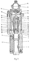
- the striking tool has a housing 1, which is composed of several cylindrical parts. The parts are partly welded together and partly clamped by screws 2 inserted in the longitudinal direction. A chisel 4 is held in the lower part of the housing 1 by means of a locking pin 3. An intermediate piston 5 is provided above the chisel 4 and is guided through a guide bush 6 inserted into the housing 1.
- the hydraulic drive of the striking tool orders from a piston rod 7, which is held immovably within the housing 1.
- a cylinder 8 is also provided, which is closed by a lower striking plate 9 facing the intermediate piston 5 and an upper cover 10 and has a central piston chamber 11.
- the cylinder 8 is guided by a cylindrical guide section 12 which is fastened to the housing 1 via struts 13.
- the piston rod 7 is passed through a rod bore in the cover 10 of the cylinder 8 and protrudes into the piston chamber 11 so that the cylinder 8 can slide on the fixed piston rod 7.
- the housing 1 is provided with an oil supply 14 which opens into a reservoir 15 and into a bore 16 which is arranged in the longitudinal axis of the piston rod 7.
- the memory 15 is placed on the housing 1 and crossed by a membrane 17.
- the bore 16 in the piston rod 7 ends just below the entry of the piston rod 7 into the piston chamber 11 in two transverse bores 18, 19 which lead to an annular space 20 within the cylinder 8.
- an axial bore 21 is arranged in the wall of the cylinder 8, which connects the annular space 20 to an upper transverse bore 22 which, starting from the axial bore 21, is guided through the wall of the cylinder 8 into the piston space 11.
- a lower transverse bore 23 is provided below the upper transverse bore 22, which penetrates the entire wall of the cylinder 8 and thus connects the piston chamber 11 to the interior 24 of the housing 1.
- the housing 1 is provided with an oil drain 25, which has a connection to an interior 24 of the housing 1.
- a control piston 26 is arranged in the piston chamber 11 at a distance from the end of the piston rod 7.
- the control piston 26 has an annular groove 27 on its outside, which is connected via transverse bores 28 to a central bore 29 which penetrates part of the control piston 26 and is open to the piston chamber 11.
- the control piston 26 is displaceable within the piston chamber 11 such that, depending on its position, the annular groove 27 faces the upper transverse bore 22 connected to the oil supply 14 and the lower transverse bore 23 connected to the oil drain 25.
- the part of the piston chamber 11 below the control piston 26 is connected to a further bore 30 which is axially guided through the wall of the cylinder 8.
- This further bore 30 ends in a transverse bore 31 leading into the piston chamber 11 Position of the cylinder 8 relative to the piston rod 7, this transverse bore 31 has a connection to an annular gap 32 which is formed between the inner wall of the cylinder 8 and a reduced-diameter middle part of the piston rod 7.
- the annular gap 32 has transverse bores penetrating through the wall of the cylinder 8 33 permanent connection with the interior 24 of the housing 1 and thus with the oil drain 25.
- the impact tool described controls itself, that is, apart from control piston 26, no additional valves or slides are required to operate the impact tool. As long as the chisel is not pressed onto a solid surface, the cylinder 8 is in its lowest rest position and the pressure oil flows through the oil supply 14 through the bore 16 and the transverse bores 18 into the interior 24 and via the oil drain 25 without pressure.
- the chisel 4 In order to put the percussion tool into operation, the chisel 4 must be placed on a solid surface so that the chisel 4 presses the cylinder 8, which acts as a bear, upwards via the intermediate piston 5.
- the control piston 26 and the cylinder 8, together with the striking plate 9 and the cover 10, have the position shown in FIG. 2.
- the control piston 26 is pressurized with pressure oil by means of pressure oil via the transverse bore 31 opening into the piston chamber 11 and the axial bore 30 in the wall of the cylinder 8 on the lower control piston surface and thus shifted into the upper position.
- the reversal has the effect that the control piston 26 now assumes the position shown in FIG. 1.
- the pressure oil is passed through the axial bore 21 and the upper transverse bore 22, the annular groove 27, the transverse bores 28 and the central bore 29 of the control piston into the piston chamber 11 of the cylinder 8, so that now the annular chamber 20 and the piston chamber 11th are pressurized in the same way.
- the bear is now moved downwards until it hits the chisel 4 via the intermediate piston 5 and releases the existing kinetic energy to the chisel 4.
- the transverse bore 31 is connected to the annular gap 32 of the piston rod 7, so that the pressure oil below the control piston 26 via the axial bore 30, via the transverse bore 31, the annular gap 32 and the transverse bore 33 permanently connected to the interior 24 can escape and thereby the control piston 26 is shifted into the lower position shown in Fig. 2 and a renewed work cycle as described above is initiated again.
- the striking tool comes to a standstill when the chisel 4 is no longer in opposition.
- the bear not only reaches the striking position during the downward stroke, but also runs into the lowest position, so that the transverse bore 18 extends back into the interior 24 and the short circuit with the unpressurized oil circulation is thus restored in the manner previously described.
Landscapes
- Physics & Mathematics (AREA)
- Fluid Mechanics (AREA)
- Engineering & Computer Science (AREA)
- Mechanical Engineering (AREA)
- Percussive Tools And Related Accessories (AREA)
Claims (4)
Priority Applications (2)
| Application Number | Priority Date | Filing Date | Title |
|---|---|---|---|
| EP84114947A EP0183874B1 (fr) | 1984-12-07 | 1984-12-07 | Outil hydraulique de percussion |
| AT84114947T ATE47552T1 (de) | 1984-12-07 | 1984-12-07 | Hydraulisches schlagwerkzeug. |
Applications Claiming Priority (1)
| Application Number | Priority Date | Filing Date | Title |
|---|---|---|---|
| EP84114947A EP0183874B1 (fr) | 1984-12-07 | 1984-12-07 | Outil hydraulique de percussion |
Publications (2)
| Publication Number | Publication Date |
|---|---|
| EP0183874A1 EP0183874A1 (fr) | 1986-06-11 |
| EP0183874B1 true EP0183874B1 (fr) | 1989-10-25 |
Family
ID=8192338
Family Applications (1)
| Application Number | Title | Priority Date | Filing Date |
|---|---|---|---|
| EP84114947A Expired EP0183874B1 (fr) | 1984-12-07 | 1984-12-07 | Outil hydraulique de percussion |
Country Status (2)
| Country | Link |
|---|---|
| EP (1) | EP0183874B1 (fr) |
| AT (1) | ATE47552T1 (fr) |
Families Citing this family (2)
| Publication number | Priority date | Publication date | Assignee | Title |
|---|---|---|---|---|
| DE59406589D1 (de) * | 1993-03-30 | 1998-09-10 | Integral Medizintechnik | Pneumatisches Schlagwerkzeug |
| US8695726B2 (en) * | 2010-12-29 | 2014-04-15 | Medical Enterprises LLC | Electric motor driven tool for orthopedic impacting |
Citations (1)
| Publication number | Priority date | Publication date | Assignee | Title |
|---|---|---|---|---|
| DE2541949A1 (de) * | 1974-09-19 | 1976-04-01 | Raymond Int Inc | Hydraulisch angetriebene hammeranordnung |
Family Cites Families (7)
| Publication number | Priority date | Publication date | Assignee | Title |
|---|---|---|---|---|
| DE150463C (fr) * | ||||
| US3708023A (en) * | 1970-12-30 | 1973-01-02 | Inst Gornogo Dela Sibirskogo O | Self-propelled air-punching mechanism |
| US4074777A (en) * | 1974-08-08 | 1978-02-21 | Atlas Copco Aktiebolag | Pneumatic impact tool |
| AU478179B2 (en) * | 1974-09-06 | 1975-09-17 | Graeme Rear Ian | Fluid operated hammer |
| US4290489A (en) * | 1974-12-18 | 1981-09-22 | Charles Leavell | Vibrationless pneumatic tools |
| NL173719C (nl) * | 1977-01-17 | 1984-03-01 | Abraham Gien En Bernard Lionel | Pneumatische slagmachine. |
| JPS59209775A (ja) * | 1983-05-13 | 1984-11-28 | 株式会社ランドマ−クウエスト | さく岩機 |
-
1984
- 1984-12-07 EP EP84114947A patent/EP0183874B1/fr not_active Expired
- 1984-12-07 AT AT84114947T patent/ATE47552T1/de not_active IP Right Cessation
Patent Citations (1)
| Publication number | Priority date | Publication date | Assignee | Title |
|---|---|---|---|---|
| DE2541949A1 (de) * | 1974-09-19 | 1976-04-01 | Raymond Int Inc | Hydraulisch angetriebene hammeranordnung |
Also Published As
| Publication number | Publication date |
|---|---|
| ATE47552T1 (de) | 1989-11-15 |
| EP0183874A1 (fr) | 1986-06-11 |
Similar Documents
| Publication | Publication Date | Title |
|---|---|---|
| DE4115477C2 (de) | Einspritzdüse für eine Brennkraftmaschine | |
| DE60018347T2 (de) | Verbesserungen in einer variablen Ventilsteuereinrichtung für eine Brennkraftmaschine | |
| DE3125143C2 (fr) | ||
| DE1528583A1 (de) | Hydraulisch oder pneumatisch kontinuierlich betaetigter Kolbenantrieb mit hin- und hergehender Bewegung,insbesondere doppeltwirkender Druckuebersetzer | |
| DE10336327A1 (de) | Injektor für Kraftstoff-Einspritzsysteme von Brennkraftmaschinen, insbesondere von direkteinspritzenden Dieselmotoren | |
| DE3534692C2 (fr) | ||
| DE2604555B2 (de) | Einrichtung zur intermittierenden schmierung des brennraumnahen schaftbereichs eines hubventils zur gaswechselsteuerung einer brennkraftmaschine | |
| EP0058926A2 (fr) | Dispositif de fermeture pour moule | |
| DE4117735C1 (fr) | ||
| EP0183874B1 (fr) | Outil hydraulique de percussion | |
| DE3911495C1 (en) | Hydraulic valve actuation unit for piston engines | |
| DE3207995C2 (de) | Ventil für das Umsteuern der Kolbenbewegung einer hydraulischen Zylinder-Kolbeneinheit | |
| DE3731240C2 (de) | Einspritzvorrichtung | |
| DE2161459C3 (de) | Hydrostatisch angetriebene Doppelpumpe | |
| DD151343A5 (de) | Hydraulisch angetriebene und elektrisch gesteuerte kraftstoffeinspritzpumpe | |
| DE3336684C2 (fr) | ||
| DE19757157C2 (de) | Hydraulischer Linearantrieb | |
| DE3021633A1 (de) | Mehrstufiger hydraulischer teleskopzylinder | |
| DE4032668C1 (en) | Hydraulic cylinder assembly - has small dia. piston guided in bore of large piston, cooperating with two sprung latches | |
| DE2164549A1 (de) | Dampfmaschine | |
| DE2065829A1 (de) | Hydraulisch angetriebene dreizylindrige schubkolbenpumpe | |
| DE2129905A1 (de) | Steuervorrichtung zum Steuern der Verschiebung eines Organs,beispielsweise des Absperrkoerpers eines Absperrschiebers | |
| AT350340B (de) | Fettschmierpresse | |
| DE2806929A1 (de) | Fluidbetaetigter servomotor | |
| DE2939576A1 (de) | Folgesteuerung fuer wenigstens zwei doppeltwirkende, druckmittelbetaetigte arbeitszylinder |
Legal Events
| Date | Code | Title | Description |
|---|---|---|---|
| PUAI | Public reference made under article 153(3) epc to a published international application that has entered the european phase |
Free format text: ORIGINAL CODE: 0009012 |
|
| AK | Designated contracting states |
Kind code of ref document: A1 Designated state(s): AT BE CH FR GB IT LI LU NL SE |
|
| 17P | Request for examination filed |
Effective date: 19861113 |
|
| 17Q | First examination report despatched |
Effective date: 19880422 |
|
| GRAA | (expected) grant |
Free format text: ORIGINAL CODE: 0009210 |
|
| AK | Designated contracting states |
Kind code of ref document: B1 Designated state(s): AT BE CH FR GB IT LI LU NL SE |
|
| REF | Corresponds to: |
Ref document number: 47552 Country of ref document: AT Date of ref document: 19891115 Kind code of ref document: T |
|
| GBT | Gb: translation of ep patent filed (gb section 77(6)(a)/1977) | ||
| ET | Fr: translation filed | ||
| ITF | It: translation for a ep patent filed | ||
| PLBE | No opposition filed within time limit |
Free format text: ORIGINAL CODE: 0009261 |
|
| STAA | Information on the status of an ep patent application or granted ep patent |
Free format text: STATUS: NO OPPOSITION FILED WITHIN TIME LIMIT |
|
| 26N | No opposition filed | ||
| PGFP | Annual fee paid to national office [announced via postgrant information from national office to epo] |
Ref country code: LU Payment date: 19921119 Year of fee payment: 9 |
|
| PGFP | Annual fee paid to national office [announced via postgrant information from national office to epo] |
Ref country code: SE Payment date: 19921120 Year of fee payment: 9 Ref country code: CH Payment date: 19921120 Year of fee payment: 9 Ref country code: AT Payment date: 19921120 Year of fee payment: 9 |
|
| PGFP | Annual fee paid to national office [announced via postgrant information from national office to epo] |
Ref country code: BE Payment date: 19921230 Year of fee payment: 9 |
|
| EPTA | Lu: last paid annual fee | ||
| PG25 | Lapsed in a contracting state [announced via postgrant information from national office to epo] |
Ref country code: LU Free format text: LAPSE BECAUSE OF NON-PAYMENT OF DUE FEES Effective date: 19931207 Ref country code: AT Effective date: 19931207 |
|
| PG25 | Lapsed in a contracting state [announced via postgrant information from national office to epo] |
Ref country code: SE Effective date: 19931208 |
|
| PG25 | Lapsed in a contracting state [announced via postgrant information from national office to epo] |
Ref country code: LI Effective date: 19931231 Ref country code: CH Effective date: 19931231 Ref country code: BE Effective date: 19931231 |
|
| BERE | Be: lapsed |
Owner name: SCHWARZ FRIEDHELM Effective date: 19931231 |
|
| REG | Reference to a national code |
Ref country code: CH Ref legal event code: PL |
|
| EUG | Se: european patent has lapsed |
Ref document number: 84114947.9 Effective date: 19940710 |
|
| PGFP | Annual fee paid to national office [announced via postgrant information from national office to epo] |
Ref country code: GB Payment date: 19971203 Year of fee payment: 14 |
|
| PG25 | Lapsed in a contracting state [announced via postgrant information from national office to epo] |
Ref country code: GB Free format text: LAPSE BECAUSE OF NON-PAYMENT OF DUE FEES Effective date: 19981207 |
|
| GBPC | Gb: european patent ceased through non-payment of renewal fee |
Effective date: 19981207 |
|
| PGFP | Annual fee paid to national office [announced via postgrant information from national office to epo] |
Ref country code: NL Payment date: 20031128 Year of fee payment: 20 |
|
| PGFP | Annual fee paid to national office [announced via postgrant information from national office to epo] |
Ref country code: FR Payment date: 20031209 Year of fee payment: 20 |
|
| PG25 | Lapsed in a contracting state [announced via postgrant information from national office to epo] |
Ref country code: NL Free format text: LAPSE BECAUSE OF EXPIRATION OF PROTECTION Effective date: 20041207 |
|
| NLV7 | Nl: ceased due to reaching the maximum lifetime of a patent |
Effective date: 20041207 |