EP0183920A2 - Verfahren zum Betreiben eines Nachwärmofens und Nachwärmofen für Brammen, Blöcke od.dgl - Google Patents
Verfahren zum Betreiben eines Nachwärmofens und Nachwärmofen für Brammen, Blöcke od.dgl Download PDFInfo
- Publication number
- EP0183920A2 EP0183920A2 EP85110663A EP85110663A EP0183920A2 EP 0183920 A2 EP0183920 A2 EP 0183920A2 EP 85110663 A EP85110663 A EP 85110663A EP 85110663 A EP85110663 A EP 85110663A EP 0183920 A2 EP0183920 A2 EP 0183920A2
- Authority
- EP
- European Patent Office
- Prior art keywords
- furnace
- hot
- gases
- heating
- mixing chamber
- Prior art date
- Legal status (The legal status is an assumption and is not a legal conclusion. Google has not performed a legal analysis and makes no representation as to the accuracy of the status listed.)
- Ceased
Links
Images


Classifications
-
- F—MECHANICAL ENGINEERING; LIGHTING; HEATING; WEAPONS; BLASTING
- F27—FURNACES; KILNS; OVENS; RETORTS
- F27B—FURNACES, KILNS, OVENS OR RETORTS IN GENERAL; OPEN SINTERING OR LIKE APPARATUS
- F27B9/00—Furnaces through which the charge is moved mechanically, e.g. of tunnel type; Similar furnaces in which the charge moves by gravity
- F27B9/30—Details, accessories or equipment specially adapted for furnaces of these types
- F27B9/3005—Details, accessories or equipment specially adapted for furnaces of these types arrangements for circulating gases
-
- C—CHEMISTRY; METALLURGY
- C21—METALLURGY OF IRON
- C21D—MODIFYING THE PHYSICAL STRUCTURE OF FERROUS METALS; GENERAL DEVICES FOR HEAT TREATMENT OF FERROUS OR NON-FERROUS METALS OR ALLOYS; MAKING METAL MALLEABLE, e.g. BY DECARBURISATION OR TEMPERING
- C21D9/00—Heat treatment, e.g. annealing, hardening, quenching or tempering, adapted for particular articles; Furnaces therefor
- C21D9/0081—Heat treatment, e.g. annealing, hardening, quenching or tempering, adapted for particular articles; Furnaces therefor for slabs; for billets
-
- F—MECHANICAL ENGINEERING; LIGHTING; HEATING; WEAPONS; BLASTING
- F27—FURNACES; KILNS; OVENS; RETORTS
- F27B—FURNACES, KILNS, OVENS OR RETORTS IN GENERAL; OPEN SINTERING OR LIKE APPARATUS
- F27B9/00—Furnaces through which the charge is moved mechanically, e.g. of tunnel type; Similar furnaces in which the charge moves by gravity
- F27B9/06—Furnaces through which the charge is moved mechanically, e.g. of tunnel type; Similar furnaces in which the charge moves by gravity heated without contact between combustion gases and charge; electrically heated
- F27B9/10—Furnaces through which the charge is moved mechanically, e.g. of tunnel type; Similar furnaces in which the charge moves by gravity heated without contact between combustion gases and charge; electrically heated heated by hot air or gas
-
- F—MECHANICAL ENGINEERING; LIGHTING; HEATING; WEAPONS; BLASTING
- F27—FURNACES; KILNS; OVENS; RETORTS
- F27B—FURNACES, KILNS, OVENS OR RETORTS IN GENERAL; OPEN SINTERING OR LIKE APPARATUS
- F27B9/00—Furnaces through which the charge is moved mechanically, e.g. of tunnel type; Similar furnaces in which the charge moves by gravity
- F27B9/14—Furnaces through which the charge is moved mechanically, e.g. of tunnel type; Similar furnaces in which the charge moves by gravity characterised by the path of the charge during treatment; characterised by the means by which the charge is moved during treatment
- F27B9/20—Furnaces through which the charge is moved mechanically, e.g. of tunnel type; Similar furnaces in which the charge moves by gravity characterised by the path of the charge during treatment; characterised by the means by which the charge is moved during treatment the charge moving in a substantially straight path
- F27B9/22—Furnaces through which the charge is moved mechanically, e.g. of tunnel type; Similar furnaces in which the charge moves by gravity characterised by the path of the charge during treatment; characterised by the means by which the charge is moved during treatment the charge moving in a substantially straight path on rails, e.g. under the action of scrapers or pushers
-
- F—MECHANICAL ENGINEERING; LIGHTING; HEATING; WEAPONS; BLASTING
- F27—FURNACES; KILNS; OVENS; RETORTS
- F27B—FURNACES, KILNS, OVENS OR RETORTS IN GENERAL; OPEN SINTERING OR LIKE APPARATUS
- F27B9/00—Furnaces through which the charge is moved mechanically, e.g. of tunnel type; Similar furnaces in which the charge moves by gravity
- F27B9/30—Details, accessories or equipment specially adapted for furnaces of these types
- F27B9/36—Arrangements of heating devices
-
- F—MECHANICAL ENGINEERING; LIGHTING; HEATING; WEAPONS; BLASTING
- F27—FURNACES; KILNS; OVENS; RETORTS
- F27B—FURNACES, KILNS, OVENS OR RETORTS IN GENERAL; OPEN SINTERING OR LIKE APPARATUS
- F27B9/00—Furnaces through which the charge is moved mechanically, e.g. of tunnel type; Similar furnaces in which the charge moves by gravity
- F27B9/30—Details, accessories or equipment specially adapted for furnaces of these types
- F27B9/38—Arrangements of devices for charging
-
- F—MECHANICAL ENGINEERING; LIGHTING; HEATING; WEAPONS; BLASTING
- F27—FURNACES; KILNS; OVENS; RETORTS
- F27B—FURNACES, KILNS, OVENS OR RETORTS IN GENERAL; OPEN SINTERING OR LIKE APPARATUS
- F27B9/00—Furnaces through which the charge is moved mechanically, e.g. of tunnel type; Similar furnaces in which the charge moves by gravity
- F27B9/30—Details, accessories or equipment specially adapted for furnaces of these types
- F27B2009/305—Particular conformation of the furnace
- F27B2009/3055—Non-uniform section through the length of the furnace
-
- F—MECHANICAL ENGINEERING; LIGHTING; HEATING; WEAPONS; BLASTING
- F27—FURNACES; KILNS; OVENS; RETORTS
- F27B—FURNACES, KILNS, OVENS OR RETORTS IN GENERAL; OPEN SINTERING OR LIKE APPARATUS
- F27B9/00—Furnaces through which the charge is moved mechanically, e.g. of tunnel type; Similar furnaces in which the charge moves by gravity
- F27B9/30—Details, accessories or equipment specially adapted for furnaces of these types
- F27B9/36—Arrangements of heating devices
- F27B2009/3607—Heaters located above the track of the charge
- F27B2009/3615—Burner in the ceiling directed vertically downwards
-
- F—MECHANICAL ENGINEERING; LIGHTING; HEATING; WEAPONS; BLASTING
- F27—FURNACES; KILNS; OVENS; RETORTS
- F27B—FURNACES, KILNS, OVENS OR RETORTS IN GENERAL; OPEN SINTERING OR LIKE APPARATUS
- F27B9/00—Furnaces through which the charge is moved mechanically, e.g. of tunnel type; Similar furnaces in which the charge moves by gravity
- F27B9/30—Details, accessories or equipment specially adapted for furnaces of these types
- F27B9/38—Arrangements of devices for charging
- F27B2009/382—Charging
-
- F—MECHANICAL ENGINEERING; LIGHTING; HEATING; WEAPONS; BLASTING
- F27—FURNACES; KILNS; OVENS; RETORTS
- F27M—INDEXING SCHEME RELATING TO ASPECTS OF THE CHARGES OR FURNACES, KILNS, OVENS OR RETORTS
- F27M2001/00—Composition, conformation or state of the charge
- F27M2001/15—Composition, conformation or state of the charge characterised by the form of the articles
- F27M2001/1539—Metallic articles
- F27M2001/1547—Elongated articles, e.g. beams, rails
- F27M2001/1552—Billets, slabs
Definitions
- the invention relates to a method for operating a reheating furnace according to the preamble of the main claim and to a reheating furnace for slabs, blocks or the like according to the preamble of claim 5.
- Modern reheating furnaces must therefore be matched to this cooperative heating and operating sequence in terms of their process engineering and construction. In such modern reheating furnaces, it should be possible to heat cold heating material and heating and equalization of the temperature of hot material with temperatures from 1100 to 1260 ° C. Furthermore, there should be sufficient and quickly usable storage space to reduce the production influence of downtimes.
- the heating of hot material with temperatures of 1100 to 1260 ° C mostly focuses only on the edges and marginal zones, since these areas are subject to increased cooling on the way from the continuous caster to the heating furnace.
- the invention has for its object to provide a reheating furnace, which allows an individual hot gas control depending on the heat, but at the same time has an integrated in the heating system, sufficiently large storage zone to act as a buffer zone and so as to influence the production of Reduce downtimes.
- the furnace according to the invention it is possible to heat cold material which is only present in a proportion of 10% of the products. At the same time the heating can be done from medium-warm material at temperatures from 400 to 1110 ° C, and finally it is possible to achieve the heating and the compensation of material with temperatures 1100 to 1260 o C.
- 1 denotes a heating furnace designed as a walking beam furnace, in which a corresponding walking beam conveyor device is provided for the actual heating material 2.
- the heating material 2 is fed to the heating furnace 1 on the feed side via a charging machine 4, the feed side being able to be closed by a corresponding door 17.
- the charging machine 4 can in Wasserge Drive in cooled raceways 3 of the furnace, this area being referred to as storage zone 5, which results in a storage space which can store approximately 50% or more of the hourly furnace reference power.
- the water-cooled raceways 3, which, with the interposition of the impellers, support the charging machine 4, permit a considerable extension of the storage zone 5 known per se.
- an exhaust manifold 6 On the top of the heating furnace 1 and on the back of the same, an exhaust manifold 6 is provided. 7 designates a hot gas fan, which is arranged, for example with respect to the path of the exhaust gases, behind a recuperator and which, via a corresponding line 18, feeds the gases withdrawn from the exhaust gas manifold 6 to a mixing chamber 8, into which the schematically indicated burners 9 open.
- the mixing chamber 8 is equipped with a hot gas outflow opening 11 which leads to the furnace interior 10.
- the hot gas outflow opening 11 is connected to one or more hot gas channels 13 which have outflow openings 12 which then open into the furnace chamber 10.
- the hot material 2 located in the furnace chamber 10 is washed around by the hot gases and heated to be ready for rolling.
- the hot gas temperature is always set in such a way that, compared to the maximum temperature of the material to be heated, there is only a slight temperature difference outside the more cooled edge zones, which is not sufficient to overheat those parts of the heat material which have a significantly higher temperature than the edge zones.
- a hot gas temperature of 1260 - 1270 ° C is set at a surface temperature of the material to be heated outside the peripheral zones of 1250 ° C. This prevents harmful overheating.
- the cooled peripheral zones of the material to be heated are heated to approximately 1250 ° C. in technically justifiable reheating times, FIG. 4 showing a corresponding temperature distribution.
- a cooling device 15 can also be provided between the exhaust gas manifold 6 and the hot gas fan 7, and the cooling medium, for example air, is only applied to it when the maximum limit temperature of the recirculated exhaust gases, for example 700 ° C., is reached.
- the cooling medium for example air
- the furnace is equipped with two exhaust manifolds 6, which are arranged next to one another at a certain distance.
- the first exhaust manifold in the direction of the feed-removal side could then only be used by the hot gas fan 7 for the return, while the second exhaust manifold could work on the recuperator and the chimney.
- the system is also suitable for heating cold or medium-warm material.
- the lower furnace is also heated by the hot gas channels 13.
- the exhaust gas quantity recirculation is then largely throttled or switched off completely to increase the hot gas temperature.
- burners 16 can be switched on at the upper furnace, so that a corresponding Lei performance increase of the entire heating system is achievable.
- the burners 9 and 16 are generally not connected to the exhaust gas recirculation system, although direct exposure of each burner to recirculated exhaust gases would also be possible.
Landscapes
- Engineering & Computer Science (AREA)
- Mechanical Engineering (AREA)
- General Engineering & Computer Science (AREA)
- Chemical & Material Sciences (AREA)
- Combustion & Propulsion (AREA)
- Physics & Mathematics (AREA)
- Thermal Sciences (AREA)
- Crystallography & Structural Chemistry (AREA)
- Materials Engineering (AREA)
- Metallurgy (AREA)
- Organic Chemistry (AREA)
- Waste-Gas Treatment And Other Accessory Devices For Furnaces (AREA)
- Heat Treatments In General, Especially Conveying And Cooling (AREA)
- Tunnel Furnaces (AREA)
Abstract
Description
- Die Erfindung bezieht sich auf ein Verfahren zum Betreiben eines Nachwärmofens entsprechend dem Oberbegriff des Hauptanspruches und auf einen Nachwärmofen für Brammen, Blöcke od. dgl. entsprechend dem Oberbegriff des Anspruches 5.
- In der Stahlindustrie ist es ein Bestreben, den Betrieb der Stranggießanlagen immer mehr mit dem Betrieb der Walzstraßen abzustimmen. Durch diese Maßnahme soll erreicht werden, daß die Brammen oder Blöcke entweder direkt verwalzt oder möglichst warm in die Nachwärmöfen einlaufen. Hierdurch lassen sich die Energiekosten für die walzreife Erwärmung beträchtlich reduzieren.
- Moderne Nachwärmöfen müssen deshalb auf diesen kooperativen Erwärmungs- und Betriebsablauf in ihrer verfahrenstechnischen und konstruktiven Konzeption abgestimmt werden. In solchen modernen Nachwärmöfen soll eine Erwärmung von kaltem Wärmgut möglich sein und eine Erwärmung und ein Ausgleich der Temperatur von Wärmgut mit Temperaturen von 1100 bis 1260° C. Weiterhin sollte eine ausreichende und schnell belegbare Speicherfläche vorhanden sein, um den Produktionseinfluß von Störzeiten zu vermindern.
- Hierbei konzentriert sich das Erwärmen von Wärmgut mit Temperaturen von 1100 bis 1260° C meist nur auf die Kanten und Randzonen, da diese Gebiete auf dem Weg von der Stranggießanlage zum Wärmofen einer verstärkten Abkühlung unterliegen.
- Bei Brammen hat zum Beispiel jener Teil außerhalb der Randzonen bereits Temperaturen, die für den Walzvorgang ausreichen oder darüberliegen und es ist eine abgestimmte Erwärmung für diesen Teil erforderlich, um auf diese Weise überhitzungen zu vermeiden.
- Der Erfindung liegt die Aufgabe zugrunde, einen Nachwärmofen zu schaffen, der in Abhängigkeit des jeweils vorhandenen Wärmgutes eine individuelle Heißgassteuerung ermöglicht, der dabei gleichzeitig aber eine in das Heizsystem integrierte, ausreichend große Speicherzone besitzt, um als Pufferzone zu wirken und um derart den Produktionseinfluß von Störzeiten zu vermindern.
- Diese der Erfindung zugrundeliegende Aufgabe wird durch die Lehre des kennzeichnenden-Teiles des Hauptanspruches und durch die Lehre des kennzeichnenden Teiles des Anspruches 5 gelöst.
- Vorteilhafte Ausgestaltungen der Erfindung sind in den Unteransprüchen erläutert.
- Mit dem erfindungsgemäßen Ofen ist es möglich, kaltes Material zu erwärmen, das nur in einem Anteil von 10 % der Produkte vorliegt. Gleichzeitig kann die Erwärmung von mittelwarmem Material mit Temperaturen von 400 bis 1110° C erfolgen und schließlich ist es möglich, die Erwärmung und den Ausgleich von Material mit Temperaturen von 1100 bis 1260o C zu erreichen.
- Ein Ausführungsbeispiel eines erfindungsgemäßen Ofens wird nachfolgend anhand der Zeichnungen erläutert.
- In den Zeichnungen zeigt
- Fig. 1 einen schematischen Längsschnitt durch einen Hubbalkenofen, in
- Fig. 2 einen Querschnitt durch den Ofen gemäß Fig. 1, in
- Fig. 3 einen Querschnitt durch die Speicherzone des Ofens, in
- Fig. 4 eine Temperaturverteilung in einer Bramme mit eingezeichneten Isothermen und in
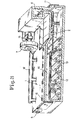
- Fig. 5 eine schaubildliche Darstellung des Ofens gemäß Fig. 2 im Schnitt gemäß der Linie 5 - 5 in Fig. 2.
- In den Zeichnungen ist mit 1 ein als Hubbalkenofen ausgebildeter Wärmofen bezeichnet, in dem eine entsprechende Hubbalkenfördereinrichtung für das eigentliche Wärmgut 2 vorgesehen ist. Das Wärmgut 2 wird über eine Chargiermaschine 4 dem Wärmofen 1 an der Aufgabeseite zugeführt, wobei die Aufgabeseite durch eine entsprechende Tür 17 verschlossen werden kann. Die Chargiermaschine 4 kann dabei in wassergekühlte Laufbahnen 3 des Ofens einfahren, wobei dieser Bereich als Speicherzone 5 bezeichnet wird, die einen Speicherplatz ergibt, der ca. 50 % oder mehr der stündlichen Ofenreferenzleistung speichern kann. Die wassergekühlten Laufbahnen 3, die unter Zwischenschaltung der Laufräder eine Abstützung der Chargiermaschine 4 bewirken, ermöglichen eine beträchtliche Verlängerung der an sich bisher bekannten Speicherzone 5.
- An der Oberseite des Wärmofens 1 und an der Rückseite desselben ist eine Abgassammelleitung 6 vorgesehen. Mit 7 ist ein Heißgasventilator bezeichnet, der beispielsweise bezüglich des Weges der Abgase hinter einem Rekuperator angeordnet ist und der über eine entsprechende Leitung 18 die aus der Abgassammelleitung 6 abgezogenen Gase einer Mischkammer 8 zuführt, in die schematisch angedeutete Brenner 9 münden. Die Mischkammer 8 ist mit einer Heißgasausströmöffnung 11 ausgerüstet, die zum Ofeninneren 10 führt. Die Heißgasausströmöffnung 11 steht dabei mit einem oder mehreren Heißgaskanälen 13 in Verbindung, die Ausströmöffnungen 12 aufweisen, die dann in den Ofenraum 10 münden. Das im Ofenraum 10 befindliche Wärmgut 2 wird von den Heißgasen umspült und walzreif erwärmt.
- Die Heißgastemperatur wird dabei stets so angesetzt, daß gegenüber der maximalen Wärmguttemperatur außerhalb der stärker abgekühlten Randzonen nur eine geringe Temperaturdifferenz auftritt, die nicht zu einer überhitzung jener Wärmgutteile ausreicht, die eine wesentlich höhere Temperatur als die Randzonen aufweisen.
- So wird z.B. bei einer Wärmgutoberflächentemperatur außerhalb der Randzonen von 1250° C eine Heißgastemperatur von 1260 - 1270° C eingestellt. Hierdurch ist eine schädliche überhitzung ausgeschlossen.
- Die abgekühlten Randzonen des Wärmgutes werden dagegen in technisch vertretbaren Nachwärmzeiten auf ca. 1250° C aufgeheizt, wobei die Fig. 4 eine entsprechende Temperaturverteilung zeigt.
- Aus Sicherheitsgründen kann zusätzlich zwischen der Abgassammelleitung 6 und dem Heißgasventilator 7 eine Kühleinrichtung 15 vorgesehen sein, die nur dann mit dem Kühlmedium, z.B. Luft, beaufschlagt wird, wenn die maximale Grenztemperatur der rückgeführten Abgase, z.B. 7000 C, erreicht wird.
- Es ist auch grundsätzlich denkbar, daß der Ofen mit zwei Abgassammelleitungen 6 ausgerüstet wird, die in einem gewissen Abstand nebeneinander angeordnet sind. Die erste Abgassammelleitung in Richtung Aufgabe-Entnahmeseite könnte dann nur vom Heißgasventilator 7 für die Rückführung benutzt werden, während die zweite Abgassammelleitung auf den Rekuperator und den Kamin arbeiten könnte.
- Die Anlage ist auch für die Erwärmung von kaltem oder mittelwarmem Wärmgut geeignet. Der Unterofen wird in einem solchen Fall ebenfalls durch die Heißgaskanäle 13 beheizt. Die Abgasmengenrückführung wird dann jedoch weitgehend gedrosselt oder ganz abgeschaltet, um die Heißgastemperatur zu erhöhen.
- Zusätzlich können Brenner 16 am Oberofen eingeschaltet werden, so daß eine entsprechende Leistungssteigerung des gesamten Beheizungssystems erreichbar ist.
- Die Brenner 9 und 16 sind in der Regel nicht an das Abgasrückführungssystem angeschlossen, obwohl eine direkte Beaufschlagung eines jeden Brenners mit rückgeführten Abgasen ebenfalls möglich wäre.
- Durch die Abgasrückführung und intensive Vermischung mit den am Brennermund austretenden Verbrennungsgasen wird die normale Verbrennungstemperatur des Brennstoffes beträchtlich herabgesetzt. Die umweltschädliche NO-Bildung dürfte dadurch um ca. 50 % reduziert werden. Dieser Vorteil ist wegen der zu beachtenden strengen NO-Vorschriften besonders kostenmäßig zu beachten.
- Bei der in Fig. 4 dargestellten Bramme ist die Temperaturverteilung durch die Isothermen 14 dargestellt. Deutlich ist der Temperaturabfall zu den Kanten hin erkennbar. Die Zahlen an den Isothermen zeigen die Temperaturen an.
Claims (10)
Applications Claiming Priority (2)
| Application Number | Priority Date | Filing Date | Title |
|---|---|---|---|
| DE3440048A DE3440048C1 (de) | 1984-11-02 | 1984-11-02 | Nachwaermofen fuer Brammen oder Bloecke |
| DE3440048 | 1984-11-02 |
Publications (2)
| Publication Number | Publication Date |
|---|---|
| EP0183920A2 true EP0183920A2 (de) | 1986-06-11 |
| EP0183920A3 EP0183920A3 (de) | 1987-06-16 |
Family
ID=6249311
Family Applications (1)
| Application Number | Title | Priority Date | Filing Date |
|---|---|---|---|
| EP85110663A Ceased EP0183920A3 (de) | 1984-11-02 | 1985-08-24 | Verfahren zum Betreiben eines Nachwärmofens und Nachwärmofen für Brammen, Blöcke od.dgl |
Country Status (3)
| Country | Link |
|---|---|
| US (1) | US4629418A (de) |
| EP (1) | EP0183920A3 (de) |
| DE (1) | DE3440048C1 (de) |
Cited By (1)
| Publication number | Priority date | Publication date | Assignee | Title |
|---|---|---|---|---|
| EP0274206A3 (en) * | 1987-01-07 | 1989-08-16 | British Gas Plc | Heating stock in a heating chamber |
Families Citing this family (2)
| Publication number | Priority date | Publication date | Assignee | Title |
|---|---|---|---|---|
| FR2766742B1 (fr) * | 1997-07-31 | 1999-09-24 | Stein Heurtey | Dispositif de transfert entre une premiere enceinte de prechauffage et une seconde enceinte de rechauffage |
| CN119222995B (zh) * | 2024-12-05 | 2025-03-14 | 安徽陶芯科半导体新材料有限公司 | 一种应用于dcb覆铜陶瓷基板生产用的网带式气氛烧结炉 |
Family Cites Families (8)
| Publication number | Priority date | Publication date | Assignee | Title |
|---|---|---|---|---|
| US3148868A (en) * | 1960-03-24 | 1964-09-15 | United States Steel Corp | Reheating furnace |
| US3212763A (en) * | 1964-03-05 | 1965-10-19 | United States Steel Corp | Reheating furnace |
| US3540706A (en) * | 1969-02-19 | 1970-11-17 | Salem Brosius Inc | Heating furnace with skid rails |
| LU65915A1 (de) * | 1972-08-17 | 1974-02-21 | ||
| JPS5154813A (en) * | 1974-11-08 | 1976-05-14 | Chugai Ro Kogyo Kaisha Ltd | Marukohenkanetsuro |
| DE2713014C2 (de) * | 1977-03-24 | 1983-09-08 | Westerhoff, Heinz, Dipl.-Ing., 4330 Mülheim | Vorrichtung zum Kühlen der Auflagen für das Wärmgut eines Wärmofens |
| JPS58105468U (ja) * | 1982-01-13 | 1983-07-18 | 中外炉工業株式会社 | アツプセツト付パイプの連続式熱処理炉 |
| DE3339585C1 (de) * | 1983-11-02 | 1987-11-12 | Didier Engineering Gmbh, 4300 Essen | Wärmofen zum Nachwärmen von Röhren, Sonderprofilen und dergleichen Wärmgut |
-
1984
- 1984-11-02 DE DE3440048A patent/DE3440048C1/de not_active Expired
-
1985
- 1985-08-24 EP EP85110663A patent/EP0183920A3/de not_active Ceased
- 1985-10-09 US US06/785,777 patent/US4629418A/en not_active Expired - Fee Related
Cited By (1)
| Publication number | Priority date | Publication date | Assignee | Title |
|---|---|---|---|---|
| EP0274206A3 (en) * | 1987-01-07 | 1989-08-16 | British Gas Plc | Heating stock in a heating chamber |
Also Published As
| Publication number | Publication date |
|---|---|
| US4629418A (en) | 1986-12-16 |
| EP0183920A3 (de) | 1987-06-16 |
| DE3440048C1 (de) | 1986-03-27 |
Similar Documents
| Publication | Publication Date | Title |
|---|---|---|
| DE69529459T2 (de) | Nichtoxidierendes heizverfahren und vorrichtung | |
| EP2717008A2 (de) | Gasdichter schutzgasbegaster Industrieofen, insbesondere Kammerofen, Durchstossofen, Drehherdofen oder Ringherdofen | |
| DE69216440T3 (de) | Tunnelsystem zum Verbinden eines Warmbandwalzwerkes mit einer Stranggussanlage für dünne Platten | |
| EP0236666B1 (de) | Arbeitsverfahren zum Aufheizen von in Stranggusseinrichtungen gegossenen oder in Umformeinrichtungen umgeformten Halbzeugen für deren Einbringen in Umform- und/oder Weiterverarbeitungseinrichtungen | |
| DE3238546A1 (de) | Verfahren zum heizen eines ofens | |
| DE102022208767A1 (de) | Anlage und Verfahren zur Herstellung von Walzprodukten | |
| DE3026020C2 (de) | Verfahren und Vorrichtung zum Ausgleichen lokaler Temperaturunterschiede auf einem Stahlerzeugnis | |
| EP4408595B1 (de) | Anlage und verfahren zur herstellung von flachwalzprodukten | |
| EP0183920A2 (de) | Verfahren zum Betreiben eines Nachwärmofens und Nachwärmofen für Brammen, Blöcke od.dgl | |
| DE60207095T2 (de) | Verfahren zur vergleichmässigung des temperaturprofills eines ofens | |
| DE2323805A1 (de) | Waermeofen | |
| EP0808672B1 (de) | Verfahren und Anlage zur Herstellung von Edelstahl- oder Kohlenstoffstahlblech aus durch Strangguss erzeugten Dünnbrammen | |
| DE3232596A1 (de) | Verfahren zum beheizen eines ofens | |
| EP1198690B1 (de) | Vorwärmeinrichtung | |
| DE3442707A1 (de) | Verfahren zum betreiben eines waermofens fuer brammen o.dgl. und waermofen fuer brammen, bloecke o.dgl. | |
| AT390322B (de) | Vorrichtung zum durchwaermen von stahlteilen | |
| EP3517509B1 (de) | Vorrichtung und verfahren zum beheizen und transportieren einer glasschmelze | |
| DE688094C (de) | ||
| DE2363476C2 (de) | StoBofenanlage zur Erwärmung von Stahlbrammen wie Transformatorenstahl bis auf eine Walztemperatur um 1400 Grad C | |
| DE69204102T2 (de) | Hubbalkenofen mit zentraler Ladung zum Beheizen und Speichern von Warmgut. | |
| DE2951826C2 (de) | Metallurgisches Schmelz- und Frischaggregat | |
| DE1263792C2 (de) | Durchlaufbrennofen | |
| EP4015657B1 (de) | Thermisches behandeln von bauteilen | |
| DE19639298A1 (de) | Verfahren und Vorrichtung zur Erzeugung von dünnen Brammen mit direkt anschließendem Walzprozeß/Walzwerk | |
| DE1199301B (de) | Waermofen fuer metallisches Gut |
Legal Events
| Date | Code | Title | Description |
|---|---|---|---|
| PUAI | Public reference made under article 153(3) epc to a published international application that has entered the european phase |
Free format text: ORIGINAL CODE: 0009012 |
|
| AK | Designated contracting states |
Kind code of ref document: A2 Designated state(s): AT BE FR SE |
|
| PUAL | Search report despatched |
Free format text: ORIGINAL CODE: 0009013 |
|
| RHK1 | Main classification (correction) |
Ipc: F27B 9/36 |
|
| AK | Designated contracting states |
Kind code of ref document: A3 Designated state(s): AT BE FR SE |
|
| 17P | Request for examination filed |
Effective date: 19870521 |
|
| 17Q | First examination report despatched |
Effective date: 19880727 |
|
| STAA | Information on the status of an ep patent application or granted ep patent |
Free format text: STATUS: THE APPLICATION HAS BEEN REFUSED |
|
| 18R | Application refused |
Effective date: 19890513 |
|
| RIN1 | Information on inventor provided before grant (corrected) |
Inventor name: PATALON, HEINRICH, DIPL.-ING. |