EP0183943A2 - Elément de support et de fermeture pour un récipient - Google Patents
Elément de support et de fermeture pour un récipient Download PDFInfo
- Publication number
- EP0183943A2 EP0183943A2 EP85112836A EP85112836A EP0183943A2 EP 0183943 A2 EP0183943 A2 EP 0183943A2 EP 85112836 A EP85112836 A EP 85112836A EP 85112836 A EP85112836 A EP 85112836A EP 0183943 A2 EP0183943 A2 EP 0183943A2
- Authority
- EP
- European Patent Office
- Prior art keywords
- holding
- closing element
- recess
- element according
- housing
- Prior art date
- Legal status (The legal status is an assumption and is not a legal conclusion. Google has not performed a legal analysis and makes no representation as to the accuracy of the status listed.)
- Withdrawn
Links
Images



Classifications
-
- B—PERFORMING OPERATIONS; TRANSPORTING
- B65—CONVEYING; PACKING; STORING; HANDLING THIN OR FILAMENTARY MATERIAL
- B65D—CONTAINERS FOR STORAGE OR TRANSPORT OF ARTICLES OR MATERIALS, e.g. BAGS, BARRELS, BOTTLES, BOXES, CANS, CARTONS, CRATES, DRUMS, JARS, TANKS, HOPPERS, FORWARDING CONTAINERS; ACCESSORIES, CLOSURES, OR FITTINGS THEREFOR; PACKAGING ELEMENTS; PACKAGES
- B65D35/00—Pliable tubular containers adapted to be permanently or temporarily deformed to expel contents, e.g. collapsible tubes for toothpaste or other plastic or semi-liquid material; Holders therefor
- B65D35/56—Holders for collapsible tubes
- B65D35/565—Holders for collapsible tubes the holder being attached to a wall or suspended from a panel
-
- B—PERFORMING OPERATIONS; TRANSPORTING
- B65—CONVEYING; PACKING; STORING; HANDLING THIN OR FILAMENTARY MATERIAL
- B65D—CONTAINERS FOR STORAGE OR TRANSPORT OF ARTICLES OR MATERIALS, e.g. BAGS, BARRELS, BOTTLES, BOXES, CANS, CARTONS, CRATES, DRUMS, JARS, TANKS, HOPPERS, FORWARDING CONTAINERS; ACCESSORIES, CLOSURES, OR FITTINGS THEREFOR; PACKAGING ELEMENTS; PACKAGES
- B65D51/00—Closures not otherwise provided for
- B65D51/24—Closures not otherwise provided for combined or co-operating with auxiliary devices for non-closing purposes
- B65D51/249—Closures not otherwise provided for combined or co-operating with auxiliary devices for non-closing purposes the closure being specifically formed for supporting the container
Definitions
- the invention relates to a holding and closing element for a container and, insofar as it relates to the features of the preamble of claim 1, is known from GB-PS 646 854.
- the holding magnet of this holding and closing element is horseshoe-shaped and is accommodated in a two-part housing which can be rigidly attached to a wall in such a way that its two poles, as magnetic holding surfaces, limit the opening of the recess.
- the pole faces are at an angle to each other, and to apply the necessary holding force, the horseshoe magnet must be very large and heavy.
- the metallic holding part on the container is a conical ring with a rubber insert, which should allow screwing onto different threads.
- various holding and closing elements are known from US Pat. No. 2,766,909 and have, as a common feature, a tubular outlet piece with a radial flange that can be screwed onto the container and overlaps the container opening.
- the holding magnet is in turn horseshoe-shaped or two magnets are provided which lie in the main plane parallel to the flange in the housing.
- the housing is arranged on a holder or can be e.g. Attach to a glass shelf with a clamp.
- the arrangement and position of the holding magnets is unsuitable, so that very strong and therefore expensive magnets have to be used.
- the magnetic force is hardly sufficient to carry a container or tube that is still full.
- DE-GM 7 227 485 finally shows and describes a holding magnet and a screw element which is screwed onto the container. Both parts have a very large material thickness and flat end faces as holding and contact surfaces. The end faces are in the plane of the container opening and therefore do not allow hygienically clean handling.
- the invention is therefore based on the object of providing measures so that holding and closing elements of the type of interest here can actually be manufactured and used commercially. It is a further object of the invention to specify a large number of possible, practically usable embodiments.
- the various features allow the production and use of fully functional holding and closing elements that meet practical needs.
- the above features or groups of features primarily contribute to clean, hygienic handling. This aspect plays a very important role, because there are often residues in the area of the container opening after removal and there is therefore a great risk that such residues will contaminate the holding and closing element. However, any contamination is unsanitary and can impair the function by reducing the magnetic force.
- the frustoconical shape of the magnetic surface contributes significantly to hygienic handling because it is off allowance with a large inner diameter and thus leads to a large free space with optimal holding force.
- the guide part also increases the hygienic and clean handling, as does the freely movable design or design or the detachability of the housing from a carrier, because the holding and closing element can thereby be cleaned again in a simple manner.
- the design with an upward recess has a favorable effect on clean, hygienic handling, because a container is easier to insert into the element if the recess is clearly visible.
- a metallic holding part in the form of a ring with an inner edge running as a thread is also very cheap from a hygienic point of view, because such a holding part can be extremely thin. A particularly large distance between the container opening and the holding part is thereby achieved. The risk of pollution is therefore low.
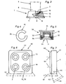
- a holding and closing element 1 according to FIGS. 1-3 has a housing 2 with a recess 3, into which a container 4 with its container opening 5 that is not closed can be inserted.
- the container 4 is tubular and has at its end 6 a conical intermediate piece 7 and a threaded piece 8 with the container opening 5.
- the housing 2 is bowl-shaped or cup-shaped and has a standing area 9.
- the opening 3 is directed upwards with its opening 10, so that the container 4 is to be inserted with its opening 5 downwards.
- the recess 3 consists of an essentially cylindrical part which adjoins the opening 10 and serves as a guide 11, a conical intermediate part 12 and an essentially cylindrical part 13 with a smaller diameter.
- the lower or inner part 13 of the recess 3 receives the threaded part 8 with the opening 5 from the inserted container 4, as shown in FIG. 3.
- the conical part 12 is delimited by a frustoconical magnetic surface 14 of a holding magnet, which acts as a support surface or shoulder 15.
- the magnetic surface 14 is the one pole surface of the holding magnet 15.
- a base 16 closes the recess 3.
- a seal 17 can be provided on the base 16, but it is not absolutely necessary in all cases and is therefore shown in broken lines in FIG. 1.
- a metallic holding part 19, which can be fastened to the container 4, is used to generate the necessary holding and closing force on the container 4 with the aid of the holding magnet 15.
- the holding part 19 is ring-shaped or a conical disk with end faces 20, 21 adapted to the frustoconical magnetic surface 14.
- the holding part 19 has an opening 22 with at least one thread 23, so that it can be screwed onto the threaded piece 8 of the container 4.
- the holding magnet 15 is expediently made of a magnetic foil material and is produced in the form of an open ring 24 as a stamped part or cut out and then bent into the desired shape and fixed captively in the recess 3 in the region of an undercut 25.
- a plurality of small, possibly differently shaped, round or square magnetic surfaces 26 or magnets can be arranged along a truncated cone surface 27 according to the dashed lines in FIG. 2 and together form an essentially frustoconical magnetic surface.
- the guide 11 in the region of the opening 10 of the recess 3 is intended to prevent the opening 5 of the container 4 from touching the magnetic surface 14 when it is inserted. As a rule, this is ensured if the length L of the guide (FIG. 1) is approximately the same or slightly greater than the remaining length R of the threaded piece 8 (FIG. 3) after the holding part 19 has been screwed on.
- FIG. 5 shows a holding and closing element 30, which comprises a housing 31 and an additionally provided carrier 32.
- the housing 31 is detachably arranged on the carrier 32.
- a screw connection 33 with an external thread on the housing 31 and an internal thread on the support 32 expediently serves this purpose.
- the carrier 32 is with a holding surface 34 in any position, i.e. hanging, standing or inclined on a base e.g. by gluing or the like attached.
- the recess 3 in the housing 31 has the same shape as in the embodiment described first. The only difference is that a detachable ring 35 forms the guide 11 and can be screwed or clipped onto the housing 31 (not shown). A detachable element forming the guide 11 can in principle also be provided in all other exemplary embodiments.
- the holding magnet 36 consists of a magnetic material with a sufficient magnetic force for a hanging container.
- FIG. 6 and 7 show a holding and closing element 40 with a plurality of recesses 3. It comprises a housing 41 in which, according to the exemplary embodiment, four recesses 3 with their holding magnets 15 or 36 are located.
- the housing 41 can have a base 9, so that the recesses 3 are open upwards.
- Feet 42 or 43 shown in dashed lines can also be arranged on the housing 41 so that the axes 44 of the recesses 3 are horizontal or are inclined to the base 45 of the foot 42 or 43. Any position for the axes 44 of the recess 3 is therefore basically conceivable.
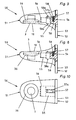
- a holding and closing element 50 which comprises a housing 51 with a recess 3 and a carrier 52 which has a base plate 53 and is glued or screwed to a wall.
- the housing 51 is detachably arranged on the carrier 52, in principle in two positions. According to FIG. 8, the opening 3 points upwards with its opening 10, while according to FIG. 9 it is directed downwards.
- a releasable and reversible arrangement of the housing 51 on the carrier 52 is expediently a snap-in connection 54 and a support 55 projecting from the base plate 53 of the carrier 52, onto which the housing 51 can be positively attached with a recess 56.
- a locking element 57 in the form of a spring-loaded ball, which, depending on the installation position, either snaps into one of two recesses 58 in the housing 51 and thereby fixes it on the support 55.
- the latching connection 54 has a latching element, for example in the form of a resilient arm 57a with a projection, which in one of two recesses 58a (dashed lines in FIGS. 8 to 10) Housing 51 engages.
- the support 55 and the recess 56 have the same shape in cross section and are, for example, rectangular or oval.
- the holding magnet 36 in turn consists of a magnetic material with sufficient holding force for carrying hanging containers.
- the housing 61 is detachably fastened to a carrier 62 and from a position with the recess 3 upwards (FIG. 11) to a position with the recess 3 downwards (FIG . 12) swiveling.
- the carrier 62 comprises e.g. on a wall attachable base plate 64 and a support member 65, on which a holder 66 with a recess 67 can be pushed and fastened to it with the aid of a latching connection 68 in a detachable manner.
- the holder 66 is fork-shaped and has arms 69 for mounting the housing 61 by means of two axes 70.
- the holder 6G encompasses the pivotable housing 61 from axis 70 to axis 70 with a projecting edge 71 (FIG. 12) in a substantially positive manner (FIG. 13).
- the housing 61 has two rib-shaped projections 72, 73 diametrically to the axes 70, which cooperate with the edge 71 of the holder 66. 11, the projection 72 lies on the top of the edge 71 when the recess 3 is pivoted upwards, while the projection 73 rests on the bottom of the edge 71 when the recess 3 is pivoted downwards (FIG. 12) the intersecting axes 44 and 70 lie in parallel planes.
- the position of the edge 71 can in principle also be selected (dashed line in FIG. 11) such that the axis 44 is vertical even when the recess 3 is pivoted upwards.
- the 15 shows a holding part 80 which, in one piece, consists of a frustoconical or conical disk 81 with a cylindrical ring collar 82 on the large circumference.
- the opening 22 in turn has at least one thread 23 or threaded pieces.
- the holding part 80 differs from the holding part 19 only by the cylindrical ring collar 82, which allows a more convenient handling when screwing onto the threaded piece 8 of the container 4 if the material thickness of the holding part 80 is extremely thin.
- 16 and 17 show a further, modified holding part 84 with conical end faces 20, 21 as when holding Part 19.
- a ring collar 82 can be provided and is therefore shown in dashed lines in FIG. 16.
- a difference to the holding parts 19 and 80 is that the inner edge 85 of the opening 22 runs directly in the form of a thread 86.
- This thread 86 begins at a shoulder 87, rises from there gradually according to the pitch of the thread on the threaded piece 8 of the container 4 and ends again at the shoulder 87 at a level which is higher by the pitch of the container thread. This is shown in dashed lines in FIG.
- FIG. 18 and 19 show a holding part 93 consisting of a conical disk 91 and optionally a cylindrical ring collar 92 (dashed line in FIG. 18) with an opening 22, from which short, essentially radially extending incisions 94 into the conical disk 91 extend.
- the incisions 94 divide the inner edge 85 of the opening 22 into a plurality of edge pieces 95-98.
- These edge pieces 95 - 98 serve to form thread passages and are shaped for this purpose in such a way that their free edges 99 facing the opening 22 run in accordance with the thread of the container. It is also expedient if adjacent edge pieces or thread pieces are at the level of different thread turns, while diametrically arranged thread pieces 95 and 97 or 96 and 98 each belong to one and the same thread turn.
- the container is a tube or bottle.
- Plastic is preferably used as the material for the holding and closing elements, but metal or ceramic can also be used will.
- the features of the various exemplary embodiments are also interchangeable, i.e. e.g.
- the housing on the carrier 52 can also have a plurality of recesses 3 for a plurality of containers or a detachable ring 35 as a guide.
Landscapes
- Engineering & Computer Science (AREA)
- Mechanical Engineering (AREA)
- Details Of Rigid Or Semi-Rigid Containers (AREA)
- Closures For Containers (AREA)
- Table Equipment (AREA)
- Packaging Frangible Articles (AREA)
Applications Claiming Priority (2)
| Application Number | Priority Date | Filing Date | Title |
|---|---|---|---|
| DE3444071 | 1984-12-03 | ||
| DE19843444071 DE3444071A1 (de) | 1984-12-03 | 1984-12-03 | Halter fuer behaelter |
Publications (2)
| Publication Number | Publication Date |
|---|---|
| EP0183943A2 true EP0183943A2 (fr) | 1986-06-11 |
| EP0183943A3 EP0183943A3 (fr) | 1987-02-04 |
Family
ID=6251783
Family Applications (1)
| Application Number | Title | Priority Date | Filing Date |
|---|---|---|---|
| EP85112836A Withdrawn EP0183943A3 (fr) | 1984-12-03 | 1985-10-10 | Elément de support et de fermeture pour un récipient |
Country Status (3)
| Country | Link |
|---|---|
| EP (1) | EP0183943A3 (fr) |
| JP (1) | JPS61178851A (fr) |
| DE (1) | DE3444071A1 (fr) |
Cited By (4)
| Publication number | Priority date | Publication date | Assignee | Title |
|---|---|---|---|---|
| EP0543111A3 (en) * | 1991-09-26 | 1993-06-23 | Leifheit Aktiengesellschaft | Rack for condiment dispensers |
| WO2007011260A1 (fr) * | 2005-07-18 | 2007-01-25 | Aleksandr Ivanovich Voloshanuk | Porte-tube |
| WO2009091294A1 (fr) * | 2008-01-16 | 2009-07-23 | Aleksandr Ivanovich Voloshanuk | Support pour tube |
| FR3147701A1 (fr) * | 2023-04-17 | 2024-10-18 | Annamaria Faure | Dispositif permettant de dissimuler les tubes de dentifrice et simplifier l’utilisation du tube |
Families Citing this family (1)
| Publication number | Priority date | Publication date | Assignee | Title |
|---|---|---|---|---|
| US9845172B2 (en) * | 2015-09-25 | 2017-12-19 | Elc Management Llc | Screw-type closure systems with magnetic feature |
Family Cites Families (8)
| Publication number | Priority date | Publication date | Assignee | Title |
|---|---|---|---|---|
| DE7227485U (de) * | 1972-12-07 | Krueger R | Magnetverschluß- und -halterung für Tuben, Flaschen, Dosen u. ä | |
| FR907261A (fr) * | 1944-10-02 | 1946-03-07 | Socle pour maintenir verticalement les tubes en métal mou, utilisés en parfumerie,pharmacie et autres industries | |
| GB646854A (en) * | 1948-02-25 | 1950-11-29 | Albert Mervyn Dent | Improvements in or relating to bracket-like supports for collapsible tubes, bottles and like containers |
| US2766909A (en) * | 1951-03-06 | 1956-10-16 | William V Doyle | Magnetic supporting device for containers |
| US2730262A (en) * | 1952-04-24 | 1956-01-10 | Reams Hunter | Supporting and closing means for collapsible tubes |
| DE1012039B (de) * | 1955-06-17 | 1957-07-11 | Gaston Birger Fog Waagepeterse | Tubenhalter |
| DE1871567U (de) * | 1963-02-14 | 1963-05-02 | Waldemar Schneider | Halter fuer tuben od. dgl. gegenstaende. |
| DE2021741A1 (de) * | 1970-05-04 | 1971-12-02 | Otto Woelky | Magnet-Tubenhalter |
-
1984
- 1984-12-03 DE DE19843444071 patent/DE3444071A1/de not_active Withdrawn
-
1985
- 1985-10-10 EP EP85112836A patent/EP0183943A3/fr not_active Withdrawn
- 1985-12-02 JP JP60271286A patent/JPS61178851A/ja active Pending
Cited By (6)
| Publication number | Priority date | Publication date | Assignee | Title |
|---|---|---|---|---|
| EP0543111A3 (en) * | 1991-09-26 | 1993-06-23 | Leifheit Aktiengesellschaft | Rack for condiment dispensers |
| US5368203A (en) * | 1991-09-26 | 1994-11-29 | Leifheit Ag | Spice rack with magnetically held spice containers |
| AU665779B2 (en) * | 1991-09-26 | 1996-01-18 | Leifheit A.G. | Condiment container with closure member |
| WO2007011260A1 (fr) * | 2005-07-18 | 2007-01-25 | Aleksandr Ivanovich Voloshanuk | Porte-tube |
| WO2009091294A1 (fr) * | 2008-01-16 | 2009-07-23 | Aleksandr Ivanovich Voloshanuk | Support pour tube |
| FR3147701A1 (fr) * | 2023-04-17 | 2024-10-18 | Annamaria Faure | Dispositif permettant de dissimuler les tubes de dentifrice et simplifier l’utilisation du tube |
Also Published As
| Publication number | Publication date |
|---|---|
| EP0183943A3 (fr) | 1987-02-04 |
| JPS61178851A (ja) | 1986-08-11 |
| DE3444071A1 (de) | 1986-06-05 |
Similar Documents
| Publication | Publication Date | Title |
|---|---|---|
| DE60224673T2 (de) | Kulturflasche | |
| DE102004003439A1 (de) | Farbbechersystem für eine Farbspritzpistole | |
| DE1939153A1 (de) | Vorrichtung zum Aufbewahren und Servieren von Nahrungsmitteln und fuer diese Vorrichtung geeignete Kupplung zwischen zwei Kunststoffteilen | |
| DE2612561A1 (de) | Vorrichtung zur bewaesserung von blumen oder pflanzen in blumentoepfen oder blumenkaesten | |
| DE202010007534U1 (de) | Entwässerungsablauf zum Einbau in eine Bodenöffnung eines Duschplatzes | |
| EP0035779A1 (fr) | Pied amovible pour récipient cylindrique | |
| DE1003489B (de) | Topffoermiger Behaelter zur Aufzucht von Kulturpflanzen in Wohnraeumen | |
| CH464861A (de) | Rührteil für einen Magnetrührer | |
| DE2835939C2 (de) | Halterung für einen Stützstab für hochwüchsige Topfpflanzen | |
| DE202004003376U1 (de) | Farbbechersystem für eine Farbspritzpistole | |
| DE3444071A1 (de) | Halter fuer behaelter | |
| DE102006048756B3 (de) | Pflanzenbehälter | |
| EP1932972B1 (fr) | Réservoir de chasse doté d'un maintien d'inverseur combiné de soupape de remplissage et de vidange | |
| DE2627383C2 (de) | Tränkeinrichtung für Tiere, insbesondere für Kälber oder dergleichen | |
| DE523103C (de) | Befestigung von Abschlusskoerpern an der Spindel | |
| EP0613645B1 (fr) | Support d'arbre | |
| DE4037398A1 (de) | Halter, insbesondere kerzenhalter | |
| EP0330903A2 (fr) | Burette à huile et porte-burette mural | |
| AT377896B (de) | Pflanztopf | |
| DE19518477A1 (de) | Kerzenspitzer | |
| EP0896808A1 (fr) | Dispositif de support et récipient pourvu d'un dispositif de support | |
| EP3173540A1 (fr) | Module de fermeture de trou de vidange d'une cuve et procédé de montage d'un tel module | |
| EP2421421B1 (fr) | Dispositif de séparation d'un jaune du blanc d'un oeuf cassé | |
| DE10154310C2 (de) | Vorrichtung zum Reinigen und Schützen von Spirituosenportionierern | |
| DE202013102687U1 (de) | Geschirrteil sowie Besteck-Kombination und Geschirrsystem dazu |
Legal Events
| Date | Code | Title | Description |
|---|---|---|---|
| PUAI | Public reference made under article 153(3) epc to a published international application that has entered the european phase |
Free format text: ORIGINAL CODE: 0009012 |
|
| AK | Designated contracting states |
Kind code of ref document: A2 Designated state(s): AT BE CH DE FR GB IT LI NL |
|
| PUAL | Search report despatched |
Free format text: ORIGINAL CODE: 0009013 |
|
| AK | Designated contracting states |
Kind code of ref document: A3 Designated state(s): AT BE CH DE FR GB IT LI NL |
|
| STAA | Information on the status of an ep patent application or granted ep patent |
Free format text: STATUS: THE APPLICATION HAS BEEN WITHDRAWN |
|
| 18W | Application withdrawn |
Withdrawal date: 19870506 |