EP0330903A2 - Burette à huile et porte-burette mural - Google Patents
Burette à huile et porte-burette mural Download PDFInfo
- Publication number
- EP0330903A2 EP0330903A2 EP89102533A EP89102533A EP0330903A2 EP 0330903 A2 EP0330903 A2 EP 0330903A2 EP 89102533 A EP89102533 A EP 89102533A EP 89102533 A EP89102533 A EP 89102533A EP 0330903 A2 EP0330903 A2 EP 0330903A2
- Authority
- EP
- European Patent Office
- Prior art keywords
- oil
- wall
- trunk
- jug
- tip
- Prior art date
- Legal status (The legal status is an assumption and is not a legal conclusion. Google has not performed a legal analysis and makes no representation as to the accuracy of the status listed.)
- Ceased
Links
Images

Classifications
-
- F—MECHANICAL ENGINEERING; LIGHTING; HEATING; WEAPONS; BLASTING
- F16—ENGINEERING ELEMENTS AND UNITS; GENERAL MEASURES FOR PRODUCING AND MAINTAINING EFFECTIVE FUNCTIONING OF MACHINES OR INSTALLATIONS; THERMAL INSULATION IN GENERAL
- F16N—LUBRICATING
- F16N3/00—Devices for supplying lubricant by manual action
- F16N3/02—Devices for supplying lubricant by manual action delivering oil
- F16N3/04—Oil cans; Oil syringes
-
- F—MECHANICAL ENGINEERING; LIGHTING; HEATING; WEAPONS; BLASTING
- F16—ENGINEERING ELEMENTS AND UNITS; GENERAL MEASURES FOR PRODUCING AND MAINTAINING EFFECTIVE FUNCTIONING OF MACHINES OR INSTALLATIONS; THERMAL INSULATION IN GENERAL
- F16N—LUBRICATING
- F16N35/00—Storage of lubricants in engine-rooms or the like
Definitions
- the invention relates to an oil jug which can be fastened to a wall holder in a specific carrying position and has an elastically flexible trunk.
- oil jugs are usually placed on a shelf or in a drawer. So that no oil leaks out, a locking cap is provided on the proboscis opening, which is easily lost or, if it is captively connected to the oil jug by a band, hinders handling. It also gets your fingers dirty. Not only when there is no cap, but even with a cap you will place oil jugs as a precaution or try so that the tip of the trunk points upwards so that no oil can leak out. Most of the time, however, a holder must be improvised that holds the oil jug in the desired upright position.
- the invention has for its object to provide a matching combination of oil jug and wall bracket, which facilitates the handling of the oil jug and ensures in a simple manner that no oil leaks in the stored state.
- a closure cap is attached to the wall bracket at the point where the trunk tip is in the carrying position of the oil can is brought, which closes the proboscis tip of the oil can, and from which the proboscis tip can be pulled out of the wall holder when the oil can is removed.
- the closing of the oil can becomes a side effect of its stopping. Since the opening at the tip of the trunk is already closed by the hand movement required to attach the oil can to the wall holder, handling is simplified and there are no longer dirty fingers.
- the closure cap is formed by a blind hole in the wall holder, that is to say it is permanently connected to it.
- the wall holder has a clamp at the point where the trunk tip is in the carrying position of the oil can, which has a non-positive locking cap that can be placed on the trunk tip. but holds releasably.
- the closure cap can remain clamped on the wall holder.
- the oil jug can simply be attached to the wall holder again at the same time the tip of the proboscis is inserted into the clamped cap. In this case you have the simple handling mentioned above.
- the main advantage is that you do not have to get your hands dirty to remove the cap and put it back on. It cannot be lost during these brief uses of the oil can because it remains on the wall bracket.
- the cap can also be released from the clamp, whereby the trunk can serve as a lever.
- the oil can which is securely closed by the cap, can then be placed and transported in any position. After use, the cap is snapped back into the clamp when attaching the oil can to the wall bracket.
- the clamp consists of two clamping jaws molded or fastened to the wall holder, the spacing and shape of which are selected such that the closure cap can be snapped or released between the clamping jaws by movement transversely to its longitudinal axis.
- These preferably extend essentially normal to the mounting level of the wall holder, i.e. normal to the wall in the case of a mainly plate-shaped wall holder, so that not only the oil comb, but also the closure cap can be snapped onto the wall holder by a movement normal to the wall and thereby fastened.
- a further preferred embodiment of the invention provides that in the carrying position, at least next to the one axial end of the closure cap, a stop securing it in the clamped position against axial displacement is arranged.
- a stop securing it in the clamped position against axial displacement is arranged.
- two stops hold the clamped closure cap against axial displacement in both directions.
- the one stop can also simultaneously form a support surface for the trunk.
- the other stop expediently holds the cap in such an axial position that it is pressed axially firmly onto the tip of the trunk in the carrying position of the oil can.
- a very particularly secure closure of the opening in the proboscis tip is obtained by axially pressing the proboscis tip with the opening axially against the bottom of the blind hole or the clamped cap in the carrying position due to the material elasticity of the oil can or the wall holder.
- the further preferred feature can contribute that the trunk has a bellows-shaped area which ensures not only a desired flexibility of the trunk, but also its elastic flexibility in the longitudinal direction.
- the oil jug shown in the drawing designated overall by 10, has essentially the shape of an oil in small format canisters, as it is used to hold motor oil.
- the width of the oil can 10 can e.g. B. about 6 cm, the height about 7.5 cm and the depth about 2.5 cm.
- the two upper corners are chamfered.
- the right, beveled corner with reference to FIG. 1 has the shape of a one-piece molded handle 12, which extends at an angle of approximately 45 ° to the vertical side surfaces.
- the handle 12 can not serve as a handle in small format. However, it delimits an elongated access opening 14 which can be used to fasten the oil can 10 to a suitably assigned wall bracket 16.
- the substantially cuboid outer shape of the oil can 10 with a flat bottom surface 18 is also well suited for installation in an upright position.
- the flat front surface offers space for a writing field 20.
- the container of the oil can 10 has a round opening in the form of a pipe socket 22 with an external thread.
- a trunk 24 formed with an inner cannula and a suitable internal thread is screwed onto it.
- the threaded part of the trunk 24 can be formed in one piece with it.
- a union nut 26 is used instead, with which the inner end of the trunk 24 is tightened tightly and tightly against the pipe socket 22, as is also customary in such connections with union nut.
- the design of the threaded part in the form of the union nut 26, which is separate from the trunk 24, has the advantage that it can be made from a plastic of a different color than the trunk 24.
- the container of the oil can 10 is also preferably made of plastic, for example from such a transparent material that the level is visible from the outside.
- the trunk 24 has a bellows-shaped region 28 near the union nut 26, which improves the flexibility of the trunk 24 and also ensures a certain elasticity of the trunk in the longitudinal direction.
- the oil jugs are usually sold with oil filling.
- the outermost end 30 of the trunk 24 which is marked by an annular groove 32, is tightly closed.
- the outermost end 30 of the trunk 24 is cut off at the annular groove 32 and the cannula of the trunk is thereby opened. This protrudes upward at 45 ° with respect to the vertical side surfaces of the oil can container, but can be easily bent in another direction thanks to the bellows-like region 28.
- the wall bracket 16 consists of a flat base plate 34 made of plastic, which with z. B. three screw holes is formed, by means of which the wall bracket can be attached to a wall.
- Several projections formed on the base plate 34 serve to fasten the oil can 10.
- the outer contour of the wall holder 16 is adapted to the contour of the oil can.
- the base plate 34 projects upward above the oil can 10 and forms a further writing field 36 there.
- the region 36 projecting upwards stabilizes a projection 38 which engages the tip of the trunk.
- the flat projections 40 and 42 are relatively short, so that they hardly appear on the outside, only the arranged between the two projections 40 and 42, also flat and relatively narrow projection 44 extends over the entire depth of the oil can 10 and is at his free end is formed with an upwardly projecting nose 46 which engages around the lower front edge of the oil can and holds the rear wall thereof in contact with the base plate 34 of the wall holder 16.
- Another projection 48 on the base plate 34 is designed and arranged such that it fits into the through opening 14 of the oil can 10 when it is in the intended position on the projections 40, 42, 44.
- the projection 48 is provided near its upper end with a transverse slot 50 which extends to the base plate 34. Through this transverse slot 50, a spring tongue 52 is formed from the uppermost end of the projection 48, which engages around the front edge of the handle 12 with a nose-shaped projection 53 shown in broken lines in FIG holds.
- the projection 38 is formed with a blind hole 54, into which the now open tip of the proboscis 24 can be inserted after the outer end 30 has been cut off.
- the dimensions of the blind hole 54 and the trunk 24 are matched to one another such that on the one hand the diameters fit to one another and on the other hand the tip of the trunk due to the material elasticity of the oil can 10 and the trunk 24 with its bellows-like region 28 is pressed elastically against the bottom of the blind hole 54, while the oil jug assumes the position on the wall holder 16 shown in the drawing, in which it is held by the projections 40, 42, 44 and 48, 52 and the lugs 46 and 53 .
- the projection 38 is formed with an insertion region 56 which is funnel-shaped or has inclined surfaces on both sides, which facilitates the insertion of the proboscis tip into the blind hole 54.
- the insertion area 56 is not only open axially, but also laterally towards the front.
- the trunk 24 is not yet held by the blind hole 54. This is also not necessary since the cannula in the trunk 24 is still tightly closed. In this state, the end 30 of the trunk 24 bears against a support surface on the projection 38 on the outside of the blind hole 54, wherein a lateral support of the trunk end 30 can be provided by two ribs 58.
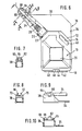
- FIGS. 6-10 differs only in the absence of the transverse slot 50 and the projection 53 and in the design of the wall holder 16 and the oil can 10 in the region of the trunk end from the embodiment according to FIGS. 1-5.
- the projection 38 forms an elevation with respect to the base plate 34, on which two clamping jaws 60, 62 are formed. Their distance is chosen so that the cap 30 sitting on the trunk 24 can be snapped between the jaws provided with an undercut, such as this can be seen from FIGS. 6, 7 and 9.
- the stop 68 prevents the closure cap 64 from axially evading.
- the stop 68 is arranged in such a position that in the carrying position shown in FIG. 6 the closure cap 64 is pressed relatively firmly and thus tightly onto the tip of the trunk 24.
- the container of the oil jug is first loosened again by loosening the nose 46 and released from the engagement with the projection 48. Then, however, the trunk 24 is not pulled out of the closure cap in the axial direction, but the container of the oil jug is further lifted off the base plate 24 and expediently simultaneously with the fingers under the elastically flexible trunk 24 grabbed. As a result, the closure cap 64 can be levered out of the clamp 60, 62. In addition, there is of course also the possibility of first pulling the closure cap 64 out of the clamp 60, 62 by reaching under the trunk 24 and then detaching the container of the oil can from the wall holder by pushing back the nose 46.
- the new oil jug with wall holder offers for the first time the option of optionally leaving a cap on the wall holder so that it can be used immediately with a single movement of the already opened oil jug, or the cap 64 together with the oil jug from Wall bracket to remove, if it should be kept locked even when removed.
Landscapes
- Engineering & Computer Science (AREA)
- General Engineering & Computer Science (AREA)
- Mechanical Engineering (AREA)
- Chemical & Material Sciences (AREA)
- Oil, Petroleum & Natural Gas (AREA)
- Loading And Unloading Of Fuel Tanks Or Ships (AREA)
- Connection Of Plates (AREA)
- Lubrication Details And Ventilation Of Internal Combustion Engines (AREA)
- Closures For Containers (AREA)
Applications Claiming Priority (4)
| Application Number | Priority Date | Filing Date | Title |
|---|---|---|---|
| DE8802650U | 1988-02-29 | ||
| DE8802650U DE8802650U1 (de) | 1988-02-29 | 1988-02-29 | Ölkännchen mit Wandhalter |
| DE8813422U | 1988-10-26 | ||
| DE8813422U DE8813422U1 (de) | 1988-10-26 | 1988-10-26 | Ölkännchen mit Wandhalter |
Publications (2)
| Publication Number | Publication Date |
|---|---|
| EP0330903A2 true EP0330903A2 (fr) | 1989-09-06 |
| EP0330903A3 EP0330903A3 (fr) | 1989-12-27 |
Family
ID=25952745
Family Applications (1)
| Application Number | Title | Priority Date | Filing Date |
|---|---|---|---|
| EP89102533A Ceased EP0330903A3 (fr) | 1988-02-29 | 1989-02-15 | Burette à huile et porte-burette mural |
Country Status (8)
| Country | Link |
|---|---|
| US (1) | US4875652A (fr) |
| EP (1) | EP0330903A3 (fr) |
| JP (1) | JPH01255797A (fr) |
| AU (1) | AU3026489A (fr) |
| DK (1) | DK92189A (fr) |
| FI (1) | FI890922A7 (fr) |
| NO (1) | NO890773L (fr) |
| PT (1) | PT89851A (fr) |
Families Citing this family (4)
| Publication number | Priority date | Publication date | Assignee | Title |
|---|---|---|---|---|
| US5088674A (en) * | 1990-07-23 | 1992-02-18 | Vertical Designs, Inc. | Bracket for wall mounting a compact disk case |
| US5238160A (en) * | 1991-04-25 | 1993-08-24 | Faulds Kevin M | Receptacle and co-operative carrier therefor |
| US6499711B1 (en) * | 2001-10-09 | 2002-12-31 | Johnsondiversey, Inc. | Dispenser wall bracket |
| USD585288S1 (en) | 2007-08-14 | 2009-01-27 | Jolly William A | Container |
Family Cites Families (12)
| Publication number | Priority date | Publication date | Assignee | Title |
|---|---|---|---|---|
| US3033404A (en) * | 1962-05-08 | Device for holding additive for motor | ||
| GB189815244A (en) * | 1898-07-12 | 1899-05-27 | Matthew Wilson | Improvements in Tobacco Pipes. |
| US1138794A (en) * | 1914-06-03 | 1915-05-11 | Oscar R Rydquist | Oil-can. |
| US1349842A (en) * | 1917-10-29 | 1920-08-17 | Willys Overland Co | Oil-can holder |
| US1584857A (en) * | 1925-05-19 | 1926-05-18 | Washburn Co | Bottle holder |
| US1810826A (en) * | 1931-01-20 | 1931-06-16 | Leil L Gray | Grease service rack |
| US2207176A (en) * | 1939-04-19 | 1940-07-09 | Harry J Phillips | Fluid can with resilient spout |
| DE819763C (de) * | 1949-11-21 | 1951-11-05 | Karl Dipl-Kfm Muehlenbeck | OElkanne, insbesondere fuer Bergwerksmaschinen |
| US2992804A (en) * | 1958-09-29 | 1961-07-18 | Hospital Drainage Corp | Receptacle holder |
| GB949491A (en) * | 1959-02-27 | 1964-02-12 | Electrolube Ltd | Improvements in dispensers for liquids or powders |
| FR2390664A1 (fr) * | 1977-05-11 | 1978-12-08 | Rochex Sa | Support, notamment a fixation murale, pour flacon distributeur |
| US4664301A (en) * | 1985-04-10 | 1987-05-12 | Nationwide Industries, Inc. | Spout and spout-holding accessory for containers |
-
1989
- 1989-02-15 EP EP89102533A patent/EP0330903A3/fr not_active Ceased
- 1989-02-22 US US07/313,494 patent/US4875652A/en not_active Expired - Fee Related
- 1989-02-23 JP JP1042017A patent/JPH01255797A/ja active Pending
- 1989-02-23 NO NO89890773A patent/NO890773L/no unknown
- 1989-02-23 AU AU30264/89A patent/AU3026489A/en not_active Abandoned
- 1989-02-27 PT PT89851A patent/PT89851A/pt not_active Application Discontinuation
- 1989-02-27 DK DK092189A patent/DK92189A/da unknown
- 1989-02-27 FI FI890922A patent/FI890922A7/fi not_active Application Discontinuation
Also Published As
| Publication number | Publication date |
|---|---|
| NO890773D0 (no) | 1989-02-23 |
| PT89851A (pt) | 1989-10-04 |
| FI890922A0 (fi) | 1989-02-27 |
| EP0330903A3 (fr) | 1989-12-27 |
| US4875652A (en) | 1989-10-24 |
| FI890922A7 (fi) | 1989-08-30 |
| DK92189D0 (da) | 1989-02-27 |
| NO890773L (no) | 1989-08-30 |
| DK92189A (da) | 1989-08-30 |
| JPH01255797A (ja) | 1989-10-12 |
| AU3026489A (en) | 1989-08-31 |
Similar Documents
| Publication | Publication Date | Title |
|---|---|---|
| DE2624478A1 (de) | Geschirrgriff aus kunststoff | |
| DE2324517B2 (de) | Tintenvorratsbehälter für Schablonenstempel | |
| DE2609073A1 (de) | Wasserauffangvorrichtung fuer ein traenkeventil | |
| DE102005050805A1 (de) | Vorrichtung zur Aufnahme von Bits | |
| DE8913997U1 (de) | Verschlußeinrichtung für ein Schaftmagazin | |
| EP0330903A2 (fr) | Burette à huile et porte-burette mural | |
| DE2835939C2 (de) | Halterung für einen Stützstab für hochwüchsige Topfpflanzen | |
| EP2160942B1 (fr) | Dispositif de soupape pour récipient de boisson par aspiration et seau de boisson par aspiration | |
| DE3640517A1 (de) | Von einem schreib- oder zeichengeraet abnehmbares huelsenfoermiges bauteil | |
| DE102020105490A1 (de) | Duschablage | |
| DE3937278C2 (de) | Vorrichtung zur Halterung eines Auslaufrohres an einem Kunststoffkanister | |
| DE2138642A1 (de) | Gießtulle fur Flüssigkeitsbehälter | |
| DE2046148A1 (de) | Druckbehälter aus mit einer Verstärkungseinlage versehenem Kunststoff | |
| DE8706939U1 (de) | Befestigung einer Tretkurbel an der Tretkurbelwelle eines Fahrrades | |
| DE8813422U1 (de) | Ölkännchen mit Wandhalter | |
| DE2627383C2 (de) | Tränkeinrichtung für Tiere, insbesondere für Kälber oder dergleichen | |
| DE1597224C (de) | Schnellvernegelung fur das Ver schlußauslosekabel einer Kamera | |
| DE2035704A1 (de) | Abdeckkappe für Inspektionsiocher | |
| DE8112525U1 (de) | Haltestutzen fuer filterbeutel | |
| DE8802650U1 (de) | Ölkännchen mit Wandhalter | |
| EP0615712B1 (fr) | Ensemble constitué de plusieurs récipients pour épices pendant d'une console | |
| DE1576462C3 (de) | Filter für Luftausgleichsöffnungen | |
| DE130478C (fr) | ||
| DE2153964C3 (de) | Baggerzahn | |
| DE8236114U1 (de) | Kuehlschranktuere |
Legal Events
| Date | Code | Title | Description |
|---|---|---|---|
| PUAI | Public reference made under article 153(3) epc to a published international application that has entered the european phase |
Free format text: ORIGINAL CODE: 0009012 |
|
| AK | Designated contracting states |
Kind code of ref document: A2 Designated state(s): AT BE CH DE ES FR GB GR IT LI LU NL SE |
|
| PUAL | Search report despatched |
Free format text: ORIGINAL CODE: 0009013 |
|
| AK | Designated contracting states |
Kind code of ref document: A3 Designated state(s): AT BE CH DE ES FR GB GR IT LI LU NL SE |
|
| 17P | Request for examination filed |
Effective date: 19891127 |
|
| 17Q | First examination report despatched |
Effective date: 19910318 |
|
| STAA | Information on the status of an ep patent application or granted ep patent |
Free format text: STATUS: THE APPLICATION HAS BEEN REFUSED |
|
| 18R | Application refused |
Effective date: 19910909 |