EP0183981A2 - Dispositif de clouage ou d'agrafage entraîné par une batterie - Google Patents
Dispositif de clouage ou d'agrafage entraîné par une batterie Download PDFInfo
- Publication number
- EP0183981A2 EP0183981A2 EP85113750A EP85113750A EP0183981A2 EP 0183981 A2 EP0183981 A2 EP 0183981A2 EP 85113750 A EP85113750 A EP 85113750A EP 85113750 A EP85113750 A EP 85113750A EP 0183981 A2 EP0183981 A2 EP 0183981A2
- Authority
- EP
- European Patent Office
- Prior art keywords
- nail
- stapler according
- switch
- capacitor
- battery
- Prior art date
- Legal status (The legal status is an assumption and is not a legal conclusion. Google has not performed a legal analysis and makes no representation as to the accuracy of the status listed.)
- Granted
Links
- 239000003990 capacitor Substances 0.000 claims abstract description 98
- 238000005265 energy consumption Methods 0.000 claims description 3
- 239000004065 semiconductor Substances 0.000 claims description 2
- 238000012544 monitoring process Methods 0.000 claims 1
- 230000001105 regulatory effect Effects 0.000 claims 1
- 238000000034 method Methods 0.000 description 13
- 230000008569 process Effects 0.000 description 13
- 230000008901 benefit Effects 0.000 description 3
- 239000000463 material Substances 0.000 description 3
- 238000004804 winding Methods 0.000 description 3
- 230000002349 favourable effect Effects 0.000 description 2
- 239000011121 hardwood Substances 0.000 description 2
- 230000001133 acceleration Effects 0.000 description 1
- 230000009286 beneficial effect Effects 0.000 description 1
- 230000003139 buffering effect Effects 0.000 description 1
- 239000003795 chemical substances by application Substances 0.000 description 1
- 238000010276 construction Methods 0.000 description 1
- 230000008878 coupling Effects 0.000 description 1
- 238000010168 coupling process Methods 0.000 description 1
- 238000005859 coupling reaction Methods 0.000 description 1
- 238000011161 development Methods 0.000 description 1
- 230000018109 developmental process Effects 0.000 description 1
- 238000007599 discharging Methods 0.000 description 1
- 230000000694 effects Effects 0.000 description 1
- 230000006870 function Effects 0.000 description 1
- 210000003205 muscle Anatomy 0.000 description 1
- 230000002028 premature Effects 0.000 description 1
- 238000011084 recovery Methods 0.000 description 1
- 230000004044 response Effects 0.000 description 1
- 230000001960 triggered effect Effects 0.000 description 1
Images
Classifications
-
- H—ELECTRICITY
- H01—ELECTRIC ELEMENTS
- H01F—MAGNETS; INDUCTANCES; TRANSFORMERS; SELECTION OF MATERIALS FOR THEIR MAGNETIC PROPERTIES
- H01F7/00—Magnets
- H01F7/06—Electromagnets; Actuators including electromagnets
- H01F7/08—Electromagnets; Actuators including electromagnets with armatures
- H01F7/18—Circuit arrangements for obtaining desired operating characteristics, e.g. for slow operation, for sequential energisation of windings, for high-speed energisation of windings
-
- B—PERFORMING OPERATIONS; TRANSPORTING
- B25—HAND TOOLS; PORTABLE POWER-DRIVEN TOOLS; MANIPULATORS
- B25C—HAND-HELD NAILING OR STAPLING TOOLS; MANUALLY OPERATED PORTABLE STAPLING TOOLS
- B25C1/00—Hand-held nailing tools; Nail feeding devices
- B25C1/06—Hand-held nailing tools; Nail feeding devices operated by electric power
Definitions
- the invention is based on a nail or stapler according to the preamble of the main claim, nail or stapler as such has long been known.
- Known nailing or stapling devices are, however, either hand-operated or are fed from the lighting network. With hand-operated devices, there is the disadvantage that the worker experiences difficulties with the hand muscles over a longer period of operation.
- the nail or stapler according to the invention with the characterizing features of the main claim has the advantage that even with relatively small Batteries sufficient energy is available for the tie rod of the device. Another advantage is that the battery is not damaged by the strong current surge that occurs when the tie rod is actuated or is supported by a memory, for example a capacitor.
- the nail or stapler according to the invention is therefore easy and small to set up and reliable.
- the switch between the capacitor and the tie rod winding is also advantageously designed as a thyristor, cold cathode thyratron or transistor. There will be no sparks when the switch is closed.
- the capacitor can be chosen smaller without the stored energy being reduced. If a very high charging voltage is sought for the capacitor, it is appropriate to multiply the voltage z. B. to choose a flyback or forward converter, with the output voltage of the capacitor is charged. This ensures that a high output voltage is achieved with very few and simple circuitry measures, which causes a high charging voltage of the capacitor. The capacitor can then be selected to be particularly small. It is also beneficial to regulate the output voltage of the converter. Even with different battery voltage, this ensures that always the same output voltage and thus the same predetermined energy is available. For this purpose, the output voltage is expediently supplied in whole or in part to a comparator which, when a predetermined voltage is exceeded, puts a switching device into operation, by means of which further operation of the converter is prevented.
- a further advantageous embodiment is given in that the selection switch can be switched over quickly during an operation. This makes it possible to trigger a double blow by first discharging part of the capacitors and then the other part of the capacitors. This is desirable, for example, to fully drive a staple into hardwood. If a higher energy is required, it is also advantageous, for example, to connect the capacitors, which are currently operated separately, in parallel, so that the impact force can be increased.
- This basic idea can advantageously also be used to build up a nailing and stapling device whose impact strength is adjustable. In this case, the number of capacitors used per impact determines the impact strength. For example, it is possible to create any impact strength by connecting one, two or more capacitors, whereby only the energy required for the driving-in process is used by the nailing and stapling device.
- FIG. 3 shows a first embodiment
- FIG. 2 shows a second embodiment
- FIG. 3 shows a third embodiment
- FIG. 4 shows a fourth embodiment of the invention
- FIG. 5 shows a fifth embodiment of the invention.
- Known electrical nailing and stapling devices comprise a housing jacket in which a coil winding is installed, the coil body of which has a continuous bore running in the coil axis as a guide for a tie rod. If a current impulse flows through the coil winding, the tie rod is pulled into the coil accelerated. The driver attached to the tie rod encounters a staple, a nail or a clip that projects into the ejection channel, separates it from the staple strip stored in the magazine and accelerates the staple in the direction of the ejection opening. There, the tacking agent is then driven into the material located under the discharge opening. The recoil force acting on the driver from the tacking means and the force of a spring bring the tie rod and driver back to their starting position, so that a new working cycle can take place.
- An accumulator or battery pack which is accommodated in the area of the device, serves as the energy source for the nailing or stapling device. Since the current through the coil is very large, the accumulator package would also have to be selected very large so that the necessary energy can be provided for the short period of the current surge. However, this leads to bulky, large devices.
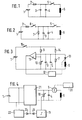
- FIG. 1 shows one possibility of how the necessary energy requirement for the coil can be provided.
- a resistor 2 is connected to an accumulator or to a battery 1, followed by two capacitors 3 and 4.
- the capacitors 3 and 4 are on the further connection the battery 1 connected.
- a line leads from the resistor 2 to a switch 5, which in turn is connected to a tie rod coil 6.
- Another pole of the battery 1 is also connected to the tie rod coil 6.
- the capacitor battery with the capacitors 3 and 4 is now charged by the battery 1 via the charging resistor 2 and corresponding energy is stored in the capacitors 3 and 4. If the switch 5 is now closed, the capacitor battery with the capacitors 3 and 4 discharges via the coil 6. After the charging process, the switch is opened again by the operator so that the capacitors 3 and 4 can be recharged.
- the resistor 2 essentially serves to limit the charging current into the capacitors 3 and 4 after a stapling process, since this would be very high in the beginning. At the same time, the charging resistance also limits the current during which the
- the buffering by means of the capacitors 3 and 4 has the effect that the accumulator 1 can be kept relatively small, since the current surge only acts for a very short time, during which it is, however, very high.
- the capacitors now prevent the voltage from breaking down due to the internal resistance of the battery. Furthermore, the unused current drain is prevented by the charging resistor, since the switch 5 is usually closed much longer than is required for the stapling process.
- the charging resistor 2 which is followed by a switch 8, is in turn connected to the battery 1.
- the capacitors 3 and 4 and additionally a resistor 7 are in turn connected in a parallel circuit, which in turn are connected to the further pole of the battery 1.
- a switch is also connected to the switch 8.
- the further connection of the switch 5 in turn leads to the tie rod coil 6, which in turn is connected to the further pole of the battery 1.
- the additional switch 8 prevents a leakage current from flowing through the capacitors 3 and 4 in the idle state of the nailing or stapling device.
- This switch is expediently actuated when the operator grips the handle of the nailing or stapling device with his hand.
- the switch is therefore advantageously housed in the handle area of the device.
- the capacitors 3 and can now be charged via the charging resistor 2. If the switch 5 is actuated, the stapling process is triggered in a known manner.
- Figure 3 shows an embodiment by which it is ensured that the stapling process is only to be initiated with charged capacitors.
- a switch 15 is connected to one pole of the battery 1 and is in turn connected to a connection of a resistor 9 and a resistor 14.
- a potentiometer 10 is connected from the resistor 9 to the other connection of the battery 1.
- a resistor 7 is connected from the resistor 14 to the other connection of the battery.
- the capacitors 3 and 4 are arranged parallel to the resistor 7.
- the midpoint between the resistors 14 and 7 is connected to a connection of a comparator 11.
- the other connection of the comparator 11 is connected to the connection point of resistors 9 and 10 in connection.
- a thyristor is also connected.
- the further connection of the thyristor 13 is connected to a connection of the tie rod coil 6.
- the other connection of the tie rod coil 6 is in turn led to the battery 1.
- the output of the comparator 11 is connected to an ignition device 12, which is constructed in a known manner and whose output is connected to the ignition connection of the thyristor 13.
- the operation of the circuit arrangement according to FIG. 3 essentially corresponds to that according to FIG. 2.
- the switch 15 is closed, the capacitors 3 and 4 are charged via the resistor 14. An actuation of the switch 5 is omitted. If the capacitors 3 and 4 are sufficiently charged, this is recognized by the comparator 11, which in turn triggers the ignition circuit 12. As a result, the thyristor 13 is turned on so that the stapling process can take place.
- the switch 15 is designed like the switch 5.
- Impact strength regulation is also possible by means of the potentiometer 10.
- the value of the potentiometer 10 makes it possible to shift the response threshold of the comparator 11, so that a stapling process takes place when the capacitors 3 and 4 have different charge levels.
- the impact strength is directly proportional to the state of charge of the capacitors 3 and 4. An ignition occurs when the state of charge of the capacitors 3 and 4 has reached the threshold value set with the potentiometer 10.
- the high-resistance resistor 7 ensures that the capacitor bank with the capacitors 3 and 4 is discharged in the idle state. To increase the energy stored in capacitors 3 and 4, it may be advisable to connect a voltage multiplier circuit. Since the energy stored in the capacitors 3 and 4 is square with the capacitor voltage, a much higher energy can be supplied to the magnet system.
- the switches 5, 8 and 15 are generally also to be replaced by thyristors, cold cathode thyratron, transistor or other semiconductor circuits. Any sparking that may occur can be avoided easily and safely.
- FIG. 4 shows a circuit arrangement in which the idea of voltage multiplication is realized by means of a flyback or forward converter.
- a flyback or forward converter 21 is connected to the battery 1, by means of which it is possible to step-up the battery voltage.
- the output voltage of the flyback converter or forward converter 21 is arbitrary within wide limits and can be chosen, for example, so that 6 coils can be used as the coil which are customary in commercially available, line-bound staple guns. However, higher or lower voltages can also be set.
- the capacitor 4, which is charged with the output voltage, is in turn connected to the output terminals of the converter 21.
- the capacitor is connected to the tie rod coil 6 via a switch 5.
- the switch 5 is formed as a cold cathode try whose control electrode is connected to an ignition circuit 20. Cold cathode thyratrons are generally known as such and, in addition to thyristors, cold cathode thyratron or transistor, are particularly suitable as electrical switches.
- a potentiometer is used to switch part of the capacitor voltage or the output voltage of the flyback converter 21. is acceptable.
- the output signal of the potentiometer 20 is fed to a comparator 11, the output of which is fed via a diode 24 to an input of the flyback converter 21.
- a timing element 22 is connected to the battery and is also fed to a further input of the flyback converter via a diode 23.
- the further input of the flyback converter 21 leads to a transistor switch, by means of which it is possible to interrupt the function of the flyback converter.
- This measure makes it possible to dispense with a manual switch-off process for the battery switch.
- the comparator 11 causes the converter 21 to be switched off so that it no longer vibrates by itself. A current draw from the battery is then interrupted.
- the same measure is achieved by the timing element 22 if the ignition switch 20 has not been actuated within a predetermined time and thus a current would be drawn from the battery 1 to maintain the charge on the capacitor 4.
- the timer 22 also causes the flyback converter 21 to be switched off via the diode 23, so that further current consumption is prevented.
- the diodes 23 and 24 only serve to decouple the switching outputs of the comparator 11 and the timing element 22.
- a new start of the converter 21 is achieved either by a switch which is arranged in the battery circuit or by a push button connected to the ignition circuit, which by a short press causes the converter to oscillate,
- a voltage is available at the output of flyback converter 21 which essentially corresponds to the peak value of the mains voltage. It is thereby achieved that the coils which have been tried and tested in network staplers can be used as coil 6.
- the energy supplied to the coil 6 is adjustable not only by the choice of the voltage on the capacitor 4 but also by a premature switch-off of the switch 5, for example if the current consumption of the coil 6 is measured or if it is determined by means of a material selection switch that for a specific driving process relatively little energy is needed.
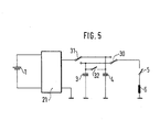
- FIG. 5 shows a battery 1 which is connected to the voltage converter 21.
- This voltage converter can be designed, for example, as a flyback converter, as in the circuit mentioned above. While one output of flyback converter 21 is grounded, the other output of flyback converter 21 leads to a further selection holder 31.
- One connection of selection switch 33 is connected to capacitor 3 and the other output of the selection switch is connected to capacitor 4.
- the selection switch 30 makes it possible to connect the switch 5 to either the capacitor 3 or the capacitor 4.
- the further connection of the switch 5 is connected to the tie rod of the nailing or stapling device.
- a switching device 32 makes it possible to connect the capacitors 3 and 4 to one another in parallel.
- the selector switches 3J and 30 are advantageously mechanically coupled to one another, so that when the switch 32 is open, one capacitor 3 is connected to the switch 5 while the other capacitor is being recharged. The nail or stapler is thereby ready for operation so that a wrapping process can be carried out while the other capacitor is being charged. If the full energy is required, the switch 32 is closed so that both capacitors are in parallel.
- the circuit arrangement is characterized by the fact that there is a shorter recovery time or a smaller construction of the voltage converter if one assumes that the full impact energy is not normally required.
Landscapes
- Engineering & Computer Science (AREA)
- Physics & Mathematics (AREA)
- Electromagnetism (AREA)
- Mechanical Engineering (AREA)
- Power Engineering (AREA)
- Portable Nailing Machines And Staplers (AREA)
Applications Claiming Priority (2)
| Application Number | Priority Date | Filing Date | Title |
|---|---|---|---|
| DE3444015 | 1984-12-03 | ||
| DE19843444015 DE3444015A1 (de) | 1984-12-03 | 1984-12-03 | Batteriebetriebenes nagel- oder klammergeraet |
Publications (3)
| Publication Number | Publication Date |
|---|---|
| EP0183981A2 true EP0183981A2 (fr) | 1986-06-11 |
| EP0183981A3 EP0183981A3 (en) | 1987-05-13 |
| EP0183981B1 EP0183981B1 (fr) | 1990-01-10 |
Family
ID=6251753
Family Applications (1)
| Application Number | Title | Priority Date | Filing Date |
|---|---|---|---|
| EP85113750A Expired - Lifetime EP0183981B1 (fr) | 1984-12-03 | 1985-10-29 | Dispositif de clouage ou d'agrafage entraîné par une batterie |
Country Status (3)
| Country | Link |
|---|---|
| EP (1) | EP0183981B1 (fr) |
| JP (1) | JPS61136777A (fr) |
| DE (2) | DE3444015A1 (fr) |
Cited By (3)
| Publication number | Priority date | Publication date | Assignee | Title |
|---|---|---|---|---|
| FR2674704A1 (fr) * | 1990-02-28 | 1992-10-02 | Arrow Fastener Cy | Appareil pour entrainer un dispositif electromagnetique et appareil alimente par des piles pour ejecter un projectile, par exemple agrafeuse electrique. |
| GB2403681A (en) * | 2003-07-09 | 2005-01-12 | Acuman Power Tools Corp | A method for controlling the operation time of an electric nailer |
| US6891457B2 (en) | 2003-02-05 | 2005-05-10 | Makita Corporation | Power tools |
Families Citing this family (4)
| Publication number | Priority date | Publication date | Assignee | Title |
|---|---|---|---|---|
| DE29708782U1 (de) * | 1997-05-16 | 1997-08-07 | Erwin Müller GmbH & Co, 49808 Lingen | Elektrisch betriebenes Heft- und Nagelgerät |
| JP4556485B2 (ja) * | 2004-05-18 | 2010-10-06 | 日立工機株式会社 | バッテリ式瞬間作動工具 |
| JP2012179664A (ja) * | 2011-02-28 | 2012-09-20 | Hitachi Koki Co Ltd | 電動式打込機及び留め具の打込み方法 |
| JP2012179661A (ja) * | 2011-02-28 | 2012-09-20 | Hitachi Koki Co Ltd | 電動式打込機及び留め具の打込み方法 |
Family Cites Families (8)
| Publication number | Priority date | Publication date | Assignee | Title |
|---|---|---|---|---|
| NL74645C (fr) * | 1948-11-09 | |||
| DE1536455A1 (de) * | 1967-08-05 | 1970-01-02 | Mueller Erwin Metall | Elektromagnetischer Heftapparat |
| DE2226788C2 (de) * | 1971-08-20 | 1974-05-22 | Erwin Mueller Kg, Metallwarenfabrik, 4450 Lingen | Nagler mit von dem Anker eines Elektromagneten angetriebenem Eintreibstößel |
| DE2537815C2 (de) * | 1975-08-25 | 1985-01-03 | Grumman Aerospace Corp., Bethpage, N.Y. | Verfahren und Vorrichtung zum Einführen eines Bolzens mit Preßsitz in eine Bohrung |
| JPS531946A (en) * | 1976-06-25 | 1978-01-10 | Nippon Door Check Mfg Co | Pivot supporting structure for swing door and pivoted door |
| US4349143A (en) * | 1980-05-12 | 1982-09-14 | Parker Manufacturing Co. | Electric stapler and driver assembly therefor |
| US4500938A (en) * | 1983-02-16 | 1985-02-19 | Textron, Inc. | Fastener driving device |
| DE3426072A1 (de) * | 1984-07-14 | 1986-01-30 | Erwin Müller GmbH & Co, 4450 Lingen | Elektrisch betriebenes heft- und nagelgeraet |
-
1984
- 1984-12-03 DE DE19843444015 patent/DE3444015A1/de not_active Ceased
-
1985
- 1985-10-29 EP EP85113750A patent/EP0183981B1/fr not_active Expired - Lifetime
- 1985-10-29 DE DE8585113750T patent/DE3575274D1/de not_active Expired - Lifetime
- 1985-12-03 JP JP60270879A patent/JPS61136777A/ja active Pending
Cited By (5)
| Publication number | Priority date | Publication date | Assignee | Title |
|---|---|---|---|---|
| FR2674704A1 (fr) * | 1990-02-28 | 1992-10-02 | Arrow Fastener Cy | Appareil pour entrainer un dispositif electromagnetique et appareil alimente par des piles pour ejecter un projectile, par exemple agrafeuse electrique. |
| GB2253953B (en) * | 1990-02-28 | 1995-07-05 | Arrow Fastener Co Inc | Apparatus for driving the armature of a battery powered device |
| US6891457B2 (en) | 2003-02-05 | 2005-05-10 | Makita Corporation | Power tools |
| GB2403681A (en) * | 2003-07-09 | 2005-01-12 | Acuman Power Tools Corp | A method for controlling the operation time of an electric nailer |
| GB2403681B (en) * | 2003-07-09 | 2005-06-29 | Acuman Power Tools Corp | Means for controlling operation of an electric nailer |
Also Published As
| Publication number | Publication date |
|---|---|
| EP0183981A3 (en) | 1987-05-13 |
| EP0183981B1 (fr) | 1990-01-10 |
| JPS61136777A (ja) | 1986-06-24 |
| DE3444015A1 (de) | 1986-06-05 |
| DE3575274D1 (de) | 1990-02-15 |
Similar Documents
| Publication | Publication Date | Title |
|---|---|---|
| EP3801990B1 (fr) | Appareil de pose | |
| EP2994273B1 (fr) | Dispositif d'entraînement et procédé d'utilisation d'un dispositif d'enfoncement | |
| DE3041944A1 (de) | Futterspannsystem | |
| DE2728485A1 (de) | Elektromagnetisch betriebene schlagvorrichtung | |
| DE2701457A1 (de) | Gleichspannungswandler | |
| DE1613338C3 (de) | Gleichspannungswandler | |
| DE102016121029A1 (de) | Elektrische Arbeitsmaschine | |
| EP0183981B1 (fr) | Dispositif de clouage ou d'agrafage entraîné par une batterie | |
| DE3426072C2 (fr) | ||
| DE102004010319B3 (de) | Elektromagnetisch betriebenes Einschlaggerät und Verfahren zum Betreiben eines elektromagnetisch betriebenen Einschlaggerätes | |
| DE2513812B1 (de) | Vorrichtung zum synchronen zuenden eines elektronenblitzgeraetes | |
| DE4241066C1 (de) | Automatische Laststromrückregelung | |
| DE19747139B4 (de) | Elektrisch betriebenes Heft- und Nagelgerät | |
| DE10113801B4 (de) | Vorrichtung zum Ansteuern wenigstens eines kapazitiven Stellgliedes und Verfahren zum Betreiben einer solchen Vorrichtung | |
| EP0998979A2 (fr) | Appareil de dosage électronique | |
| DE19536064A1 (de) | Getaktete Stromversorgungsschaltung mit einer von einem Verbraucher unabhängigen, zumindest zeitweise wirksamen Last | |
| DE2427299A1 (de) | Steuerschaltung fuer elektrisch betriebenes fahrzeug | |
| DE10127362C2 (de) | Zündanlage für eine Brennkraftmaschine | |
| EP0303599B1 (fr) | Dispositif d'allumage pour moteurs a combustion interne | |
| DE2212236C3 (de) | Schaltungsanordnung für batteriebetriebene Feuerzeuge | |
| EP0246361A2 (fr) | Appareil électronique alimenté par une batterie et commutable par interrupteur à touche | |
| DE1965152A1 (de) | Elektronisches Zuendsystem | |
| DE2733031C2 (de) | Gleichspannungswandler | |
| DE1539177C3 (de) | Zündeinrichtung für Brennkraftmaschinen | |
| EP0787062A1 (fr) | Agrafeuse electrique |
Legal Events
| Date | Code | Title | Description |
|---|---|---|---|
| PUAI | Public reference made under article 153(3) epc to a published international application that has entered the european phase |
Free format text: ORIGINAL CODE: 0009012 |
|
| AK | Designated contracting states |
Kind code of ref document: A2 Designated state(s): CH DE FR GB IT LI SE |
|
| PUAL | Search report despatched |
Free format text: ORIGINAL CODE: 0009013 |
|
| AK | Designated contracting states |
Kind code of ref document: A3 Designated state(s): CH DE FR GB IT LI SE |
|
| 17P | Request for examination filed |
Effective date: 19870404 |
|
| 17Q | First examination report despatched |
Effective date: 19880822 |
|
| GRAA | (expected) grant |
Free format text: ORIGINAL CODE: 0009210 |
|
| STAA | Information on the status of an ep patent application or granted ep patent |
Free format text: STATUS: THE PATENT HAS BEEN GRANTED |
|
| AK | Designated contracting states |
Kind code of ref document: B1 Designated state(s): CH DE FR GB IT LI SE |
|
| ET | Fr: translation filed | ||
| REF | Corresponds to: |
Ref document number: 3575274 Country of ref document: DE Date of ref document: 19900215 |
|
| GBT | Gb: translation of ep patent filed (gb section 77(6)(a)/1977) | ||
| ITF | It: translation for a ep patent filed | ||
| PLBI | Opposition filed |
Free format text: ORIGINAL CODE: 0009260 |
|
| 26 | Opposition filed |
Opponent name: ERWIN MUELLER GMBH & CO Effective date: 19900907 |
|
| ITTA | It: last paid annual fee | ||
| RAP4 | Party data changed (patent owner data changed or rights of a patent transferred) |
Owner name: ROBERT BOSCH GMBH |
|
| PLBJ | Opposition found inadmissible |
Free format text: ORIGINAL CODE: 0009275 |
|
| 26U | Opposition found inadmissible | ||
| REG | Reference to a national code |
Ref country code: GB Ref legal event code: 746 Effective date: 19941007 |
|
| PGFP | Annual fee paid to national office [announced via postgrant information from national office to epo] |
Ref country code: DE Payment date: 19941222 Year of fee payment: 10 |
|
| EAL | Se: european patent in force in sweden |
Ref document number: 85113750.5 |
|
| REG | Reference to a national code |
Ref country code: FR Ref legal event code: D6 |
|
| ITPR | It: changes in ownership of a european patent |
Owner name: OFFERTA DI LICENZA AL PUBBLICO |
|
| PGFP | Annual fee paid to national office [announced via postgrant information from national office to epo] |
Ref country code: GB Payment date: 19951009 Year of fee payment: 11 |
|
| PGFP | Annual fee paid to national office [announced via postgrant information from national office to epo] |
Ref country code: FR Payment date: 19951018 Year of fee payment: 11 |
|
| PGFP | Annual fee paid to national office [announced via postgrant information from national office to epo] |
Ref country code: SE Payment date: 19951020 Year of fee payment: 11 |
|
| PGFP | Annual fee paid to national office [announced via postgrant information from national office to epo] |
Ref country code: CH Payment date: 19951024 Year of fee payment: 11 |
|
| PG25 | Lapsed in a contracting state [announced via postgrant information from national office to epo] |
Ref country code: DE Effective date: 19960702 |
|
| PG25 | Lapsed in a contracting state [announced via postgrant information from national office to epo] |
Ref country code: GB Effective date: 19961029 |
|
| PG25 | Lapsed in a contracting state [announced via postgrant information from national office to epo] |
Ref country code: SE Effective date: 19961030 |
|
| PG25 | Lapsed in a contracting state [announced via postgrant information from national office to epo] |
Ref country code: LI Effective date: 19961031 Ref country code: CH Effective date: 19961031 |
|
| REG | Reference to a national code |
Ref country code: CH Ref legal event code: PL |
|
| GBPC | Gb: european patent ceased through non-payment of renewal fee |
Effective date: 19961029 |
|
| PG25 | Lapsed in a contracting state [announced via postgrant information from national office to epo] |
Ref country code: FR Effective date: 19970630 |
|
| EUG | Se: european patent has lapsed |
Ref document number: 85113750.5 |
|
| REG | Reference to a national code |
Ref country code: FR Ref legal event code: ST |
|
| RIN2 | Information on inventor provided after grant (corrected) |
Inventor name: WANNER, KARL, DR.-ING. Inventor name: STROHBECK, WALTER Inventor name: RUFF, MANFRED Inventor name: MOEHRING, HERMANN Inventor name: JORDAN, PETER Inventor name: BUCK, MANFRED, DIPL.-ING. |
|
| RAP2 | Party data changed (patent owner data changed or rights of a patent transferred) |
Owner name: ROBERT BOSCH GMBH |