EP0998979A2 - Appareil de dosage électronique - Google Patents
Appareil de dosage électronique Download PDFInfo
- Publication number
- EP0998979A2 EP0998979A2 EP99120596A EP99120596A EP0998979A2 EP 0998979 A2 EP0998979 A2 EP 0998979A2 EP 99120596 A EP99120596 A EP 99120596A EP 99120596 A EP99120596 A EP 99120596A EP 0998979 A2 EP0998979 A2 EP 0998979A2
- Authority
- EP
- European Patent Office
- Prior art keywords
- supply voltage
- electronic
- drive
- converter
- pipetting device
- Prior art date
- Legal status (The legal status is an assumption and is not a legal conclusion. Google has not performed a legal analysis and makes no representation as to the accuracy of the status listed.)
- Granted
Links
Images

Classifications
-
- B—PERFORMING OPERATIONS; TRANSPORTING
- B01—PHYSICAL OR CHEMICAL PROCESSES OR APPARATUS IN GENERAL
- B01L—CHEMICAL OR PHYSICAL LABORATORY APPARATUS FOR GENERAL USE
- B01L3/00—Containers or dishes for laboratory use, e.g. laboratory glassware; Droppers
- B01L3/02—Burettes; Pipettes
- B01L3/021—Pipettes, i.e. with only one conduit for withdrawing and redistributing liquids
- B01L3/0217—Pipettes, i.e. with only one conduit for withdrawing and redistributing liquids of the plunger pump type
- B01L3/0227—Details of motor drive means
-
- B—PERFORMING OPERATIONS; TRANSPORTING
- B01—PHYSICAL OR CHEMICAL PROCESSES OR APPARATUS IN GENERAL
- B01L—CHEMICAL OR PHYSICAL LABORATORY APPARATUS FOR GENERAL USE
- B01L2300/00—Additional constructional details
- B01L2300/02—Identification, exchange or storage of information
- B01L2300/025—Displaying results or values with integrated means
- B01L2300/027—Digital display, e.g. LCD, LED
Definitions
- the invention relates to an electronic dosing device.
- a syringe With direct displacement dosing devices, however, a syringe becomes direct filled with sample liquid. So the pistons and cylinders of the syringe contaminated by the liquid so that the syringe before changing the Liquid is usually replaced or cleaned with a new syringe got to.
- the syringe is also usually made of plastic.
- Air cushion, direct displacement, pistonless and microdosing devices can have an unchangeable or a variable dosing volume.
- a change in the dosing volume is done by adjusting the displacement the displacement device reached, i.e. the displacement of the Piston or the degree of deformation of the balloon-like end section or the chamber wall.
- Dispensers are dosing devices that contain an absorbed volume of liquid can deliver repetitively in small portions.
- the electrical Voltage source dimensioned so that it is sufficient in the normal state Power for the drive with all operating loads of the Provides drive device. For a battery or one Battery, this requires an appropriate number of cells. Still it can with progressive discharge and thus decreasing supply voltage increases malfunctions occur. As the supply voltage drops, namely the torque of the drive, so that the drive device the displacement device no longer with all occurring Drives loads in the desired manner. Especially when it comes to execution of the drive as a stepper motor, steps can be lost and as a result Dosing errors arise. That is why it is for reliable operation an elaborate battery or accumulator supply for a desired time with corresponding costs, volume and weight required. Same thing applies as a power supply when the electrical voltage source is used.
- the object of the invention is an electronic one To create a metering device in which the effort for electrical voltage source, in particular its costs, space requirements and Weight is reduced and the drive is nevertheless used in all operational Loads are supplied with the required voltage.
- the control and / or regulating device provides this Drive via a converter to the respective load of the drive device coordinated supply voltage available. For example, it can the supply voltage at the start of a drive process increase in order to overcome the starting resistance of the displacement device. After that, the supply voltage can be reduced to a nominal value lower that for a further drive of the displaced displacement device is sufficient. If the dosing device with different Displacement devices that can be equipped with different loads represent for the drive devices, for example syringes of different Size, the supply voltage can be applied to the respective displacement device be coordinated.
- the control and / or regulating device controls the operation of the dosing device, for example according to Control commands that can be entered from a keyboard so that they knows the respective operating state of the dosing device.
- the control and / or regulating device can apply criteria to everyone Find out a suitable supply voltage and use the operating state provide the converter.
- information about the displacement device in each case, for. B. a coding of a Syringe, automatically read by the dosing device or entered separately become.
- the control and / or regulating device the respective load that changes unpredictably due to external influences can be determined and the supply voltage based on the result of the determination regulate. So the tuning of the supply voltage be reached on the respective load.
- the invention is not limited to the use of a step-up converter.
- the case is also included in which the one required by the electric drive Supply voltage below the supply voltage of the power supply lies.
- lithium-ion (Li-ion) batteries are available, which provide a relatively high voltage (about 3V per cell), so that by connecting only a few cells in series, a relatively high supply voltage can be made available.
- the high supply voltage is partially converted into heat loss. This is undesirable for several reasons.
- the invention can now be used to down-convert the supply voltage to a supply voltage with that for the respective load required level.
- the invention also includes the case that the supply voltage from the converter both up and is also reduced, depending on the load of the drive device.
- the metering device has the advantage that the electrical Voltage source and the drive matched to an average load can be. With increased loads, the converter provides an increased supply voltage to disposal. Since these occur only for a short time, there is none Get damage to the drive motor. As a result, that comes Dosing device with a smaller number of battery cells or a smaller sized power supply than conventional dosing devices out. On the part of the electrical voltage source is a cost saving achievable that exceeds the additional costs for the converter. This also reduces the space requirement for the voltage source and a reduction in weight of the metering device is achieved. Another The advantage is that the converter also regulates the supply voltage enables so that this from the discharge state of a battery or an accumulator is largely independent.
- the electric drive can in particular be an electric drive motor, an electric linear drive or one of the associated with microdosing devices mentioned electric drives.
- the drive motor can be a stepper motor in which a Pulse control precisely defined dosing quantities or dosing steps favored.
- precisely defined dosing quantities can be used in particular through end stops, angle encoders or coding strips be ensured.
- the drive device can be a transmission for converting a Rotational movement of a shaft of a drive motor in a linear drive movement have for the displacement device.
- the displacement device is a piston-cylinder arrangement having.
- This can be the syringe of a direct displacement device or the displacement unit of an air cushion metering device act.
- the electrical voltage source can have at least one battery, at least have a battery and / or a power supply.
- NiMH batteries to be available.
- the converter can, in particular, approximately on the supply voltage Supply level of supply voltage and above. So the supply voltage in the amount of a supply voltage of z. B. 2.4 volts used be exerting a holding torque on a stepper motor that is on a Nominal voltage of e.g. B. is designed for 6 volts. Lack of such Holding torque exists with a stepper motor when braking Tendency to swing, so that he may have one or more takes unwanted steps.
- the converter can vary the supply voltage deliver discrete or continuous levels. One of them can Generate a holding torque. Another level can Nominal voltage that the drive motor with average load needed. In addition, there can be an increased voltage level for increased Give loads. Accordingly, the control and / or regulating device the supply voltage when stopping the drive motor at the low Level, with average load at the middle level and deliver at an elevated level at higher loads. For example the supply voltage the discrete values 2.4 volts, 6 volts and 8 volts accept.
- the converter preferably has a step-up converter.
- Boost converter are well-known circuits in supply engineering, with which one DC voltage can be brought to a higher level. Boost converter can put an output voltage above the input voltage, where they usually use the energy stored in an inductor.
- the electronic dosing device is preferably a hand-held device executed and accordingly with at least one battery or at least equipped with an accumulator.
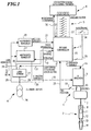
- the electronic pipetting device consists essentially from six functional areas, namely a drive device 1, one Displacement device 2, an electronic control and / or regulating device 3, an electrical voltage source 4, an operating device 5 and a display device 6. All functional areas 1 to 6 are in or on a pipette housing - not shown - of a hand pipette educated.
- the drive device 1 has an electric drive motor that is designed as a stepper motor 7.
- An axis 8 is formed by means of the stepping motor 7 can be moved linearly back and forth. It also belongs to the drive device an engine stage in the form of two H-bridges 9, the control the stepper motor 7 is used.
- the displacement device 2 has a piston 11 on the axis 8 is fixed.
- the piston 11 is displaceable in a cylinder 12. This is connected via a channel 13 to a pipette tip 14 by the device is separable.
- a microcontroller belongs to the electronic control and / or regulating device 3 15, in particular a timer, a working memory and a integrated non-volatile memory.
- the microcontroller controls the H-bridges via control lines 16.
- Step-up converter 20 Another component of the control and / or regulating device 3 is another Step-up converter 20 which supplies the microcontroller 15 with further supply. lines 21 supplied.
- the axis 8 of the stepping motor 7 is assigned a limit switch 22 which is monitored via a control line 23 by the microcontroller 15 in order to to enable zero adjustment.
- the electrical voltage source 4 comprises two NiMH batteries 24, the Supply voltage via feed lines 25, the step-up converter 17 and the further step-up converter 20 is supplied.
- the supply voltage of the two Batteries 24 are supplied to the microcontroller 15 via control lines 26.
- a charging current control is also part of the electrical voltage source 24 27, on the one hand via charging contacts 28 with an external Voltage source is connectable and on the other hand via charging lines 29 the batteries 24 is connected.
- the charging current control 27 is also over Control lines 30 for the charging voltage and via charging current control lines 31 each connected to the microcontroller 15.
- the operating device 5 comprises an input keyboard 32 which is connected via lines 33 is connected to the microcontroller 15. It also includes release buttons 34, which is connected to the microcontroller 15 via lines 35.
- the display device 6 is an LCD display which is connected via lines 36 is connected to the microcontroller 15, which contains a display control.
- the pipetting device works as follows:
- the control software is stored in the microcontroller 15. Special pipetting parameters can before the dosing process using the input keyboard 32 can be entered. Individual pipetting processes are carried out by means of the trigger buttons 34 triggerable.
- the display 6 shows entered pipetting parameters, Control commands and operating states of the pipetting device.
- the total supply voltage of the two battery cells 24 is 2.4 volts. This is from the further step-up converter 20 to 3.3 volts supply voltage regulated for the microcontroller 15.
- the step-up converter switches 17 the supply voltage of the accumulators 24 as supply voltage to the supply lines 18 through or increases this to 6 or 8 volts. Since the Microcontroller operation of the stepper motor 7 via the control lines 16 controls, it knows their respective voltage requirements and controls the step-up converter 17 accordingly.
- the supply voltage is from the microcontroller 15 via the control lines 26 checked. If it falls below a permissible value, the display shows 6 a corresponding information is output.
- the charging contacts 28 By connecting the charging contacts 28 to an external power supply can charge if necessary the batteries 24 take place.
- About the charging current control lines 31 Charging current corresponding to the state of charge determined via the control lines 30 the batteries 24 controlled.
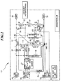
- the step-up converter 17 comprises an IC 37 of the type which is known in specialist circles as Boost converter "is known. In the example, it is the IC MAX 608 from Maxim.
- the IC 37 is connected in the usual manner with transistor 38, resistor 40, capacitors 45 to 50, diode 51 and inductor 52.
- the IC 37 regulates via the voltage feedback consisting of transistor 39 and resistors 41 to 43, the on-time of transistor 38, whereby inductor 52 is charged with energy. This energy is given as an additional series voltage source during the blocking phase of transistor 38 to output capacitors 48 and 49.
- the Voltage feedback can be switched using contact 57. Contact 57 opens low ", the supply voltage is 6V, it is on high ", it is 8V.
- the supply voltage can be set approximately to the value of the supply voltage by means of the contact 58.
- the feed lines 25 are located on the contacts 53, 54 and the supply lines 18 to the contacts 55, 56 and are the Control lines 19 connected to contacts 57, 58.
- step-up converter U A ⁇ U E x (1 + t1 / t2) where U A is the supply voltage and U E is the supply voltage.
- t1 is the time that transistor 38 is conductive and t2 is the time that transistor 38 is off.
- the transistor 38 conducts for as long as it blocks, it turns out U a ⁇ 2 x U e on. However, if the transistor blocks all the time, it turns out U a ⁇ U e on.
- the increase in the torque of the drive motor 7 results from the fixed internal motor resistance and the increased driving voltage U A.
- the electrical power that is implemented in the engine is also a measure of the available engine torque.
- An electrical voltage source 24 in the form of a battery, a rechargeable battery or a power supply unit supplies a low supply voltage to a step-up converter 17. This is controlled digitally or analogously by means of control lines 19 via the voltage factor N u and accordingly ran a supply voltage according to the product of the voltage factor N u and the supply voltage.
- This supply voltage drives the drive motor 7 via the motor output stage 9.
- a stepless variation of the voltage factor N u is also possible in order to achieve a fine adjustment to the power requirement.
Landscapes
- Health & Medical Sciences (AREA)
- Clinical Laboratory Science (AREA)
- Chemical & Material Sciences (AREA)
- Chemical Kinetics & Catalysis (AREA)
- Charge And Discharge Circuits For Batteries Or The Like (AREA)
- Devices For Use In Laboratory Experiments (AREA)
- Dc-Dc Converters (AREA)
- Structures Of Non-Positive Displacement Pumps (AREA)
- Control Of Stepping Motors (AREA)
- Infusion, Injection, And Reservoir Apparatuses (AREA)
Applications Claiming Priority (2)
| Application Number | Priority Date | Filing Date | Title |
|---|---|---|---|
| DE19850417A DE19850417C2 (de) | 1998-11-02 | 1998-11-02 | Elektronische Dosiervorrichtung |
| DE19850417 | 1998-11-02 |
Publications (3)
| Publication Number | Publication Date |
|---|---|
| EP0998979A2 true EP0998979A2 (fr) | 2000-05-10 |
| EP0998979A3 EP0998979A3 (fr) | 2002-04-10 |
| EP0998979B1 EP0998979B1 (fr) | 2008-06-11 |
Family
ID=7886388
Family Applications (1)
| Application Number | Title | Priority Date | Filing Date |
|---|---|---|---|
| EP99120596A Expired - Lifetime EP0998979B1 (fr) | 1998-11-02 | 1999-10-16 | Appareil de dosage électronique |
Country Status (4)
| Country | Link |
|---|---|
| US (1) | US6499365B1 (fr) |
| EP (1) | EP0998979B1 (fr) |
| JP (1) | JP4981200B2 (fr) |
| DE (2) | DE19850417C2 (fr) |
Cited By (2)
| Publication number | Priority date | Publication date | Assignee | Title |
|---|---|---|---|---|
| US8865474B2 (en) | 2000-12-18 | 2014-10-21 | Protedyne Corporation | Automated laboratory system |
| CN113908899A (zh) * | 2021-09-17 | 2022-01-11 | 圣湘生物科技股份有限公司 | 移液装置、核酸提取、检测装置及移液器更换方法 |
Families Citing this family (5)
| Publication number | Priority date | Publication date | Assignee | Title |
|---|---|---|---|---|
| US7396512B2 (en) | 2003-11-04 | 2008-07-08 | Drummond Scientific Company | Automatic precision non-contact open-loop fluid dispensing |
| RU2340397C2 (ru) * | 2003-11-27 | 2008-12-10 | Джилсон С.А.С. | Электронная пипетка с дисплеем и манипулятором для управления забором и распределением жидкости |
| DE102004016003B4 (de) * | 2004-04-01 | 2006-05-04 | Eppendorf Ag | Elektronische Pipette |
| CN102735305B (zh) * | 2012-06-19 | 2014-05-07 | 浙江大学 | 一种伺服电机控制的燃料测量装置 |
| JP6640998B2 (ja) | 2015-06-05 | 2020-02-05 | ミメタス ビー.ブイ. | マイクロ流体プレート |
Family Cites Families (22)
| Publication number | Priority date | Publication date | Assignee | Title |
|---|---|---|---|---|
| US4018362A (en) * | 1975-11-06 | 1977-04-19 | Union Chimique Continentale-U.C.C. | Automatic control for liquid flow |
| US4071168A (en) * | 1976-04-22 | 1978-01-31 | Pettibone Corporation | Level control system for a rotary cone-type feed hopper |
| CA1105956A (fr) * | 1978-01-09 | 1981-07-28 | William J. Bourne | Applicateur de substances granulaires |
| US4232255A (en) * | 1978-11-06 | 1980-11-04 | Carlen Eric T | Delivery control system for vehicle-mounted spreader |
| US4475666A (en) * | 1981-08-31 | 1984-10-09 | American Hospital Supply Corporation | Automated liquid dispenser control |
| US4671123A (en) * | 1984-02-16 | 1987-06-09 | Rainin Instrument Co., Inc. | Methods and apparatus for pipetting and/or titrating liquids using a hand held self-contained automated pipette |
| US4616305A (en) * | 1985-02-11 | 1986-10-07 | Eaton Corporation | AC/DC power MOSFET reversing H-drive system |
| US4964533A (en) * | 1985-03-18 | 1990-10-23 | Isco, Inc. | Pumping system |
| DE3531241A1 (de) * | 1985-08-31 | 1987-03-05 | Eppendorf Geraetebau Netheler | Vorrichtung zur gesteuerten ausgabe von fluessigkeiten |
| US4988481A (en) * | 1989-01-30 | 1991-01-29 | Labsystems Oy | Electrical pipette |
| CH678926A5 (fr) * | 1989-04-04 | 1991-11-29 | Mettler Toledo Ag | |
| JPH03188326A (ja) * | 1989-12-19 | 1991-08-16 | Aisan Ind Co Ltd | 電子式定量止水栓 |
| FI87740C (fi) * | 1990-05-04 | 1994-04-08 | Biohit Oy | Pipett |
| GB9119448D0 (en) * | 1991-09-12 | 1991-10-23 | Vickers Systems Ltd | System controls |
| US5269353A (en) * | 1992-10-29 | 1993-12-14 | Gilbarco, Inc. | Vapor pump control |
| JP3188326B2 (ja) | 1992-11-06 | 2001-07-16 | 有限会社美濃資源開発 | 溶融スラグの高級資源化方法および低温窯業焼結体の製造方法 |
| JPH08223993A (ja) * | 1995-02-16 | 1996-08-30 | Canon Inc | ステップモータの駆動制御装置 |
| US5840346A (en) * | 1995-05-26 | 1998-11-24 | Hannaford; Christopher S. | Viscous material dispensing apparatus |
| JP3648326B2 (ja) * | 1996-05-22 | 2005-05-18 | アロカ株式会社 | ピペット装置 |
| JP3694755B2 (ja) * | 1996-07-22 | 2005-09-14 | アークレイ株式会社 | ピペッティング方法、ピペッティング装置、および記憶媒体 |
| US5992686A (en) * | 1998-02-27 | 1999-11-30 | Fluid Research Corporation | Method and apparatus for dispensing liquids and solids |
| US6254832B1 (en) * | 1999-03-05 | 2001-07-03 | Rainin Instrument Co., Inc. | Battery powered microprocessor controlled hand portable electronic pipette |
-
1998
- 1998-11-02 DE DE19850417A patent/DE19850417C2/de not_active Revoked
-
1999
- 1999-10-16 DE DE59914784T patent/DE59914784D1/de not_active Expired - Lifetime
- 1999-10-16 EP EP99120596A patent/EP0998979B1/fr not_active Expired - Lifetime
- 1999-11-01 JP JP31062599A patent/JP4981200B2/ja not_active Expired - Lifetime
- 1999-11-01 US US09/431,456 patent/US6499365B1/en not_active Expired - Lifetime
Cited By (3)
| Publication number | Priority date | Publication date | Assignee | Title |
|---|---|---|---|---|
| US8865474B2 (en) | 2000-12-18 | 2014-10-21 | Protedyne Corporation | Automated laboratory system |
| CN113908899A (zh) * | 2021-09-17 | 2022-01-11 | 圣湘生物科技股份有限公司 | 移液装置、核酸提取、检测装置及移液器更换方法 |
| CN113908899B (zh) * | 2021-09-17 | 2023-05-02 | 圣湘生物科技股份有限公司 | 移液装置、核酸提取、检测装置及移液器更换方法 |
Also Published As
| Publication number | Publication date |
|---|---|
| EP0998979B1 (fr) | 2008-06-11 |
| JP2000146663A (ja) | 2000-05-26 |
| DE59914784D1 (de) | 2008-07-24 |
| DE19850417A1 (de) | 2000-05-11 |
| DE19850417C2 (de) | 2002-08-08 |
| JP4981200B2 (ja) | 2012-07-18 |
| US6499365B1 (en) | 2002-12-31 |
| EP0998979A3 (fr) | 2002-04-10 |
Similar Documents
| Publication | Publication Date | Title |
|---|---|---|
| EP0390253B1 (fr) | Dispositif chargeur pour appareils électriques munis d'accumulateurs | |
| DE19931235C2 (de) | Verfahren und Vorrichtung zum Laden eines kapazitiven Stellgliedes | |
| EP0054704B1 (fr) | Organe de réglage à corps piézo-céramique | |
| EP0054703A1 (fr) | Circuit pour organe de positionnement piézo-électrique et analogue | |
| DE102004022419B4 (de) | Pipette | |
| EP1202439A2 (fr) | Convertisseur continu-continu | |
| DE102009045891A1 (de) | Auspressvorrichtung | |
| EP0998979B1 (fr) | Appareil de dosage électronique | |
| WO2009135824A1 (fr) | Procédé et dispositif permettant de commander une servocommande | |
| DE60027829T2 (de) | Ansteuerschaltung für piezoelektrische/elektrostriktive Bauelemente | |
| WO2019233843A1 (fr) | Appareil de pose | |
| DE10301343A1 (de) | Dosiervorrichtung | |
| DE102004003838B4 (de) | Schaltungsanordnung zum Aufladen und Entladen von mehreren kapazitiven Stellgliedern | |
| DE102004030249A1 (de) | Piezoaktor-Ansteuerschaltung zur Aufladung und Entladung eines Piezoaktors | |
| DE102004026250B4 (de) | Ansteuerschaltung für Piezoaktoren | |
| DE4122984C2 (de) | Ansteuereinrichtung für eine piezoelektrische Vorrichtung und Verfahren zum Betreiben einer Ansteuereinrichtung für eine piezoelektrische Vorrichtung | |
| DE19861339B4 (de) | Elektronische Handpipettiervorrichtung | |
| EP1825123B1 (fr) | Circuit electrique pour reguler un element piezo-electrique, notamment un systeme d'injection de carburant d'automobile | |
| EP0183981B1 (fr) | Dispositif de clouage ou d'agrafage entraîné par une batterie | |
| DE10113801B4 (de) | Vorrichtung zum Ansteuern wenigstens eines kapazitiven Stellgliedes und Verfahren zum Betreiben einer solchen Vorrichtung | |
| DE19944249B4 (de) | Vorrichtung zum Ansteuern wenigstens eines kapazitiven Stellgliedes | |
| DE19653666A1 (de) | Verfahren zum schnellen Ansteuern kapazitiver Lasten | |
| EP1522005B1 (fr) | Circuiterie pour stabiliser une tension d'alimentation et procede pour faire fonctionner cette circuiterie | |
| EP1825529B1 (fr) | Circuit electrique pour reguler un element piezo-electrique, notamment d'un systeme d'injection de carburant d'automobile | |
| EP1265347A2 (fr) | Alimentation de tension de bootstrap |
Legal Events
| Date | Code | Title | Description |
|---|---|---|---|
| PUAI | Public reference made under article 153(3) epc to a published international application that has entered the european phase |
Free format text: ORIGINAL CODE: 0009012 |
|
| AK | Designated contracting states |
Kind code of ref document: A2 Designated state(s): AT BE CH CY DE DK ES FI FR GB GR IE IT LI LU MC NL PT SE Kind code of ref document: A2 Designated state(s): CH DE FI FR GB LI |
|
| AX | Request for extension of the european patent |
Free format text: AL;LT;LV;MK;RO;SI |
|
| RAP1 | Party data changed (applicant data changed or rights of an application transferred) |
Owner name: EPPENDORF AG |
|
| PUAL | Search report despatched |
Free format text: ORIGINAL CODE: 0009013 |
|
| AK | Designated contracting states |
Kind code of ref document: A3 Designated state(s): AT BE CH CY DE DK ES FI FR GB GR IE IT LI LU MC NL PT SE |
|
| AX | Request for extension of the european patent |
Free format text: AL;LT;LV;MK;RO;SI |
|
| 17P | Request for examination filed |
Effective date: 20020502 |
|
| AKX | Designation fees paid |
Free format text: CH DE FI FR GB LI |
|
| GRAP | Despatch of communication of intention to grant a patent |
Free format text: ORIGINAL CODE: EPIDOSNIGR1 |
|
| GRAS | Grant fee paid |
Free format text: ORIGINAL CODE: EPIDOSNIGR3 |
|
| GRAA | (expected) grant |
Free format text: ORIGINAL CODE: 0009210 |
|
| AK | Designated contracting states |
Kind code of ref document: B1 Designated state(s): CH DE FI FR GB LI |
|
| REG | Reference to a national code |
Ref country code: GB Ref legal event code: FG4D Free format text: NOT ENGLISH |
|
| REG | Reference to a national code |
Ref country code: CH Ref legal event code: EP |
|
| REF | Corresponds to: |
Ref document number: 59914784 Country of ref document: DE Date of ref document: 20080724 Kind code of ref document: P |
|
| REG | Reference to a national code |
Ref country code: CH Ref legal event code: NV Representative=s name: ISLER & PEDRAZZINI AG |
|
| PLBE | No opposition filed within time limit |
Free format text: ORIGINAL CODE: 0009261 |
|
| STAA | Information on the status of an ep patent application or granted ep patent |
Free format text: STATUS: NO OPPOSITION FILED WITHIN TIME LIMIT |
|
| 26N | No opposition filed |
Effective date: 20090312 |
|
| REG | Reference to a national code |
Ref country code: FR Ref legal event code: PLFP Year of fee payment: 17 |
|
| REG | Reference to a national code |
Ref country code: FR Ref legal event code: PLFP Year of fee payment: 18 |
|
| REG | Reference to a national code |
Ref country code: FR Ref legal event code: PLFP Year of fee payment: 19 |
|
| REG | Reference to a national code |
Ref country code: FR Ref legal event code: PLFP Year of fee payment: 20 |
|
| PGFP | Annual fee paid to national office [announced via postgrant information from national office to epo] |
Ref country code: DE Payment date: 20181019 Year of fee payment: 20 Ref country code: FI Payment date: 20181022 Year of fee payment: 20 |
|
| PGFP | Annual fee paid to national office [announced via postgrant information from national office to epo] |
Ref country code: GB Payment date: 20181019 Year of fee payment: 20 Ref country code: CH Payment date: 20181019 Year of fee payment: 20 Ref country code: FR Payment date: 20181022 Year of fee payment: 20 |
|
| REG | Reference to a national code |
Ref country code: DE Ref legal event code: R071 Ref document number: 59914784 Country of ref document: DE |
|
| REG | Reference to a national code |
Ref country code: CH Ref legal event code: PL |
|
| REG | Reference to a national code |
Ref country code: GB Ref legal event code: PE20 Expiry date: 20191015 |
|
| PG25 | Lapsed in a contracting state [announced via postgrant information from national office to epo] |
Ref country code: GB Free format text: LAPSE BECAUSE OF EXPIRATION OF PROTECTION Effective date: 20191015 |