EP0184004A2 - Serrure à mortaise avec cylindre profilé - Google Patents
Serrure à mortaise avec cylindre profilé Download PDFInfo
- Publication number
- EP0184004A2 EP0184004A2 EP85114039A EP85114039A EP0184004A2 EP 0184004 A2 EP0184004 A2 EP 0184004A2 EP 85114039 A EP85114039 A EP 85114039A EP 85114039 A EP85114039 A EP 85114039A EP 0184004 A2 EP0184004 A2 EP 0184004A2
- Authority
- EP
- European Patent Office
- Prior art keywords
- profile cylinder
- faceplate
- web
- screw
- lock
- Prior art date
- Legal status (The legal status is an assumption and is not a legal conclusion. Google has not performed a legal analysis and makes no representation as to the accuracy of the status listed.)
- Withdrawn
Links
Images

Classifications
-
- E—FIXED CONSTRUCTIONS
- E05—LOCKS; KEYS; WINDOW OR DOOR FITTINGS; SAFES
- E05B—LOCKS; ACCESSORIES THEREFOR; HANDCUFFS
- E05B9/00—Lock casings or latch-mechanism casings ; Fastening locks or fasteners or parts thereof to the wing
- E05B9/08—Fastening locks or fasteners or parts thereof, e.g. the casings of latch-bolt locks or cylinder locks to the wing
- E05B9/084—Fastening of lock cylinders, plugs or cores
Definitions
- the invention relates to a mortise lock with a profile cylinder inserted into laterally opposite, correspondingly profiled receiving openings of the lock housing and a fixing screw which holds it therein and engages on the profile cylinder web and which engages with a corresponding counter thread.
- Mortise locks with built-in profile cylinder of the above type are generally known.
- the faceplate screw used to fasten the profile cylinder inserted into the receptacle openings of the lock housing penetrates a cross bore in the web of the profile cylinder provided with the corresponding counter thread.
- the forend screw must Therefore, when assembling the profile cylinder, it is relatively complicated to turn it through its mating thread located in the web and then mostly through a flat pin that serves to position it, which is usually located behind the profile cylinder in the lock housing.
- the transverse bore containing the counter-thread additionally weakens the profile cylinder web, so that such a profile cylinder can be relatively easily bent or broken off at this point by the existing recess for the closing thumb and its hub, which is already weakened by external forceps .
- DE-OS 25 54 593 provides for the point at risk of demolition to be reinforced by a U-shaped bracket bridging the profile cylinder web.
- this clip with its web, requires a corresponding longitudinal recess in the profile cylinder web, the latter is hardly reinforced, but rather weakened.
- the invention has for its object to provide a mortise lock with profile cylinder, the Fastening in the lock housing can be done easily and without weakening the profile cylinder web significantly.
- This object is achieved in that the mating thread for the faceplate screw is located on a threaded body located in the interior of the lock between the faceplate and profile cylinder and the screw with the screw tip engages in a countersink on the web of the profile cylinder.
- the profile cylinder no longer needs to have a threaded hole weakening it in the area of its critical cross section, that is to say in its web.
- the faceplate screw becomes part of the mortise lock and, unlike conventional profile cylinder mounting, does not have to be adjusted to the backset of the different locks.
- the fastening of the profile cylinder requires only a few turns of the faceplate screw, since the latter only needs to be adjusted until its screw tip engages firmly in the countersink on the profile cylinder web.
- the profile cylinder is also connected to the lock in a sufficiently positive manner.
- the threaded body can be rigidly fastened in the interior of the lock in the vicinity of the receiving openings for the profile cylinder, so that it is pressed firmly against the opposite wall of the receiving openings in the lock housing when the forend screw is sufficiently tightened.
- the threaded body the faceplate of a U-shaped, which surrounds the web part of the inserted profile cylinder clamping bracket, which is axially displaceable in the lock housing in the direction perpendicular to the faceplate and is axially displaceable on its leg opposite the threaded body, pointing towards the faceplate screw tip and coaxial with it has internally projecting retaining pin which engages in a second countersink existing on the profile cylinder web.
- the clamping bracket is held in its most open position in relation to the faceplate screw tip and the holding pin by the spring in such a stop position in the lock housing that the faceplate screw tip on the one hand and the tip of the holding pin on the other are just at such a distance and in such a position relative to the Receiving openings are that the profile cylinder can be pushed past them into its central fastening position, and then by pressing the faceplate screw not only its tip in the associated countersinking of the profile cylinder web but also to the same extent by correspondingly moving the clamping bracket also its retaining pin in retracts the opposite counterbore, which ensures that the profile cylinder is fast and secure.
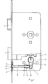
- the mortise lock shown in FIG. 1 has a faceplate 3 with corresponding through-holes for the lock latch 1 and the lock bolt 2 and a lock housing 4 firmly connected to it, which is provided on both sides with opposing profiled receiving openings 5 into which the profile lock cylinder 6 is to be inserted.
- the profile cylinder 6 is designed as a double cylinder, the two cylinder halves of which are firmly connected to one another via the profile cylinder web 7. But it can also be a single profile cylinder 6, which have a correspondingly located fastening projection or connecting web 7 at the level of the locking bit, one of which is the inner end of the profile connects half-cylinder receiving end plate with the actual cylinder.
- the faceplate screw 8 For fastening the profile cylinder 6 is the faceplate screw 8, which with its actuating end 8 'passes through a corresponding opening 3' in the faceplate 3.
- the actuating end 8 ' is usually provided with a corresponding screwdriver slot 8' '.
- the faceplate screw 8 does not reach through a corresponding threaded hole in the web 7 of the profile cylinder 6, but it is screw-adjustable in a threaded body 9 provided with a corresponding counter thread 9 ', which is located in the interior of the lock near the receiving openings 5 between the Profile cylinder 6 and the faceplate 3 and is rigidly connected to the lock housing 4 in this case.
- the faceplate screw 8 engages in a countersink 7' in the web 7 of the profile cylinder 6.
- the profile cylinder 6 can be clamped in the receiving openings effectively and with an axial positive fit by a few turns of the faceplate screw 8.
- a weakening of the profile cylinder web 7 in the form of a continuous threaded hole is not necessary here, so that the profile cylinder is correspondingly tamper-proof.
- the threaded body 10 forms the leg of the faceplate 3 of a U-shaped clamping bracket 10 which engages around the web 7 of the inserted profile cylinder 6.
- the clamping bracket 10 is axially displaceably mounted in the lock housing 4 in the direction perpendicular to the faceplate 3 and has on its leg 10 'opposite the threaded body 10'. a holding pin 11 which points towards the faceplate screw tip 8 '''and which is coaxial with it and projects inwards and which engages in a second countersink 7''on the profile cylinder web 7.
- the clamping bracket 10 is under the action of the compression spring 12 wound around the faceplate screw 8, which is on the one hand on a disc 13 lying on the inside of the faceplate 3 or on the faceplate 3, if this perforated disc is not already available for fastening the faceplate and lock case, and on the other hand is supported on the tensioning arm leg forming the threaded body 10 '.
- This compression spring 12 strives to press the clamping bracket 10 together with the forend screw 8 inserted in it in the opposite direction to the forend 3.
- the clamping bracket 10 rests under the pressure of the spring 12 with its leg 10 ′′ carrying the retaining pin 11 against the right-hand boundary wall of the guide slots 4 ′ in the lock housing 4 in the drawing. In this position, the tips of the faceplate screw 8 and the holding pin 11 are located approximately at the level of the corresponding edges 5 'of the receiving openings 5.
- the profile cylinder 6 is inserted into the receiving openings 5 inserted and then the retaining screw 8 is turned accordingly, not only does the tip 8 '''of the faceplate screw 8 enter the countersink 7', but at the same time the tensioning bracket 10 is displaced in the direction of the faceplate 3, the tip of the faceplate Retaining pin 11 in increasing engagement with the countersink 7 "of the profile cylinder web. Finally, the latter is thereby axially positively held on both sides.
- the profile cylinder web 7 does not need to be weakened in its area between the two counterbores 7 ', 7' ', so that it has an incomparably greater break-open strength than conventional profile cylinders with a web threaded bore .
- conventional profile cylinders with a continuous threaded bore 14 in the web are also suitable for the fastening according to the invention, since the threaded inlets and outlets 14 'and 14' ' also have counterbores 7' and 7 '' Form in the sense of the invention and can accordingly be brought into positive engagement with the tips of the faceplate screw 8 and the holding pin 11.
Landscapes
- Engineering & Computer Science (AREA)
- Mechanical Engineering (AREA)
- Joining Of Building Structures In Genera (AREA)
- Mutual Connection Of Rods And Tubes (AREA)
- Connection Of Plates (AREA)
Applications Claiming Priority (2)
| Application Number | Priority Date | Filing Date | Title |
|---|---|---|---|
| DE3444605 | 1984-12-07 | ||
| DE19843444605 DE3444605A1 (de) | 1984-12-07 | 1984-12-07 | Einsteckschloss mit profilzylinder |
Publications (2)
| Publication Number | Publication Date |
|---|---|
| EP0184004A2 true EP0184004A2 (fr) | 1986-06-11 |
| EP0184004A3 EP0184004A3 (fr) | 1987-05-06 |
Family
ID=6252108
Family Applications (1)
| Application Number | Title | Priority Date | Filing Date |
|---|---|---|---|
| EP85114039A Withdrawn EP0184004A3 (fr) | 1984-12-07 | 1985-11-05 | Serrure à mortaise avec cylindre profilé |
Country Status (2)
| Country | Link |
|---|---|
| EP (1) | EP0184004A3 (fr) |
| DE (1) | DE3444605A1 (fr) |
Cited By (1)
| Publication number | Priority date | Publication date | Assignee | Title |
|---|---|---|---|---|
| FR2812016A1 (fr) * | 2000-07-20 | 2002-01-25 | Bricard Sa | Dispositif de fermeture, notamment serrure, comprenant un reservoir contenant une substance anti-effraction |
Families Citing this family (2)
| Publication number | Priority date | Publication date | Assignee | Title |
|---|---|---|---|---|
| DE10103970B4 (de) * | 2001-01-30 | 2004-07-29 | Società Italiana Progetti S.r.l. | Vorrichtung zum Verriegeln einer Ganzglastür |
| DE202007017139U1 (de) | 2007-12-06 | 2009-04-09 | Kfv Karl Fliether Gmbh & Co. Kg | Schloss |
Family Cites Families (1)
| Publication number | Priority date | Publication date | Assignee | Title |
|---|---|---|---|---|
| DE2741718A1 (de) * | 1977-09-16 | 1979-03-29 | Mrt Magnet Regeltechnik Gmbh | Sicherheitsausfuehrung eines profilzylinders |
-
1984
- 1984-12-07 DE DE19843444605 patent/DE3444605A1/de not_active Withdrawn
-
1985
- 1985-11-05 EP EP85114039A patent/EP0184004A3/fr not_active Withdrawn
Cited By (1)
| Publication number | Priority date | Publication date | Assignee | Title |
|---|---|---|---|---|
| FR2812016A1 (fr) * | 2000-07-20 | 2002-01-25 | Bricard Sa | Dispositif de fermeture, notamment serrure, comprenant un reservoir contenant une substance anti-effraction |
Also Published As
| Publication number | Publication date |
|---|---|
| DE3444605A1 (de) | 1986-06-19 |
| EP0184004A3 (fr) | 1987-05-06 |
Similar Documents
| Publication | Publication Date | Title |
|---|---|---|
| DE10041984B4 (de) | Vorrichtung zur Verriegelung der Lenkspindel eines Fahrzeuges | |
| AT392818B (de) | Schliesssystem | |
| DE10146026C1 (de) | Griffbeschlag | |
| EP0175049B1 (fr) | Tourniquet susceptible d'être manoeuvré par une clé à tube | |
| EP1049845A2 (fr) | Serrure a pene demi-tour faisant saillie hors du boitier de ladite serrure | |
| EP1474212A1 (fr) | Poignee de canne avec dragonne | |
| EP1049846A1 (fr) | Serrure pour porte en verre avec un element lateral fixe en verre | |
| DE19517011A1 (de) | Vorrichtung zur Verbindung von Profilstangen insbesondere für den Möbel- und Gestellbau | |
| EP0175211A1 (fr) | Fermeture de tourniquet actionnée et arrêtée au moyen d'une clé à douille | |
| EP1256669B1 (fr) | Serrure cylindrique | |
| DE2615322C2 (de) | Befestigungsvorrichtung für Türschilder bzw. Türrosetten | |
| DE8710534U1 (de) | Profilschließzylinder mit Axialsicherung | |
| DE2525771A1 (de) | Einstecktuerschloss | |
| DE2932471A1 (de) | Schloss, insbesondere einsteckschloss | |
| DE3444605A1 (de) | Einsteckschloss mit profilzylinder | |
| DE2804603C2 (de) | Riegelblockiervorrichtung in einem Schloß mit schlüsselbetätigbarer Zuhaltung | |
| DE2911647C2 (de) | Zahnradantrieb in einem schließzylinderbetätigbaren Treibstangenschloß | |
| EP0665350B1 (fr) | Dispositif pour le montage d'un carter-support | |
| DE3533366C2 (fr) | ||
| DE9210795U1 (de) | Sicherheitsbeschlag für mit einem Profilschließzylinder versehene Türschlösser | |
| EP0270951A2 (fr) | Poignée verrouillable de fenêtre | |
| DE8435808U1 (de) | Einsteckschloß mit Profilzylinder | |
| DE19604594C1 (de) | Kombination eines Schließzylinders und eines Flachschlüssels für Waren- und Spielautomaten, Geldwechselautomaten, Fahrkartenautomaten und dergleichen, mit Stiftzuhaltungen | |
| DE3733518A1 (de) | Schliesszylinder | |
| DE29920508U1 (de) | Treibstangenschloss |
Legal Events
| Date | Code | Title | Description |
|---|---|---|---|
| PUAI | Public reference made under article 153(3) epc to a published international application that has entered the european phase |
Free format text: ORIGINAL CODE: 0009012 |
|
| AK | Designated contracting states |
Kind code of ref document: A2 Designated state(s): AT BE CH FR GB IT LI NL SE |
|
| PUAL | Search report despatched |
Free format text: ORIGINAL CODE: 0009013 |
|
| AK | Designated contracting states |
Kind code of ref document: A3 Designated state(s): AT BE CH FR GB IT LI NL SE |
|
| 17P | Request for examination filed |
Effective date: 19870609 |
|
| 17Q | First examination report despatched |
Effective date: 19871102 |
|
| STAA | Information on the status of an ep patent application or granted ep patent |
Free format text: STATUS: THE APPLICATION IS DEEMED TO BE WITHDRAWN |
|
| 18D | Application deemed to be withdrawn |
Effective date: 19880314 |
|
| RIN1 | Information on inventor provided before grant (corrected) |
Inventor name: HINZ, MANFRED |