EP0184051A1 - Flexible Ganzstahl-Wellenkupplung - Google Patents
Flexible Ganzstahl-Wellenkupplung Download PDFInfo
- Publication number
- EP0184051A1 EP0184051A1 EP85114513A EP85114513A EP0184051A1 EP 0184051 A1 EP0184051 A1 EP 0184051A1 EP 85114513 A EP85114513 A EP 85114513A EP 85114513 A EP85114513 A EP 85114513A EP 0184051 A1 EP0184051 A1 EP 0184051A1
- Authority
- EP
- European Patent Office
- Prior art keywords
- clamping
- shaft coupling
- steel shaft
- bolt
- conical
- Prior art date
- Legal status (The legal status is an assumption and is not a legal conclusion. Google has not performed a legal analysis and makes no representation as to the accuracy of the status listed.)
- Granted
Links
Images



Classifications
-
- F—MECHANICAL ENGINEERING; LIGHTING; HEATING; WEAPONS; BLASTING
- F16—ENGINEERING ELEMENTS AND UNITS; GENERAL MEASURES FOR PRODUCING AND MAINTAINING EFFECTIVE FUNCTIONING OF MACHINES OR INSTALLATIONS; THERMAL INSULATION IN GENERAL
- F16D—COUPLINGS FOR TRANSMITTING ROTATION; CLUTCHES; BRAKES
- F16D3/00—Yielding couplings, i.e. with means permitting movement between the connected parts during the drive
- F16D3/50—Yielding couplings, i.e. with means permitting movement between the connected parts during the drive with the coupling parts connected by one or more intermediate members
- F16D3/78—Yielding couplings, i.e. with means permitting movement between the connected parts during the drive with the coupling parts connected by one or more intermediate members shaped as an elastic disc or flat ring, arranged perpendicular to the axis of the coupling parts, different sets of spots of the disc or ring being attached to each coupling part, e.g. Hardy couplings
- F16D3/79—Yielding couplings, i.e. with means permitting movement between the connected parts during the drive with the coupling parts connected by one or more intermediate members shaped as an elastic disc or flat ring, arranged perpendicular to the axis of the coupling parts, different sets of spots of the disc or ring being attached to each coupling part, e.g. Hardy couplings the disc or ring being metallic
-
- F—MECHANICAL ENGINEERING; LIGHTING; HEATING; WEAPONS; BLASTING
- F16—ENGINEERING ELEMENTS AND UNITS; GENERAL MEASURES FOR PRODUCING AND MAINTAINING EFFECTIVE FUNCTIONING OF MACHINES OR INSTALLATIONS; THERMAL INSULATION IN GENERAL
- F16D—COUPLINGS FOR TRANSMITTING ROTATION; CLUTCHES; BRAKES
- F16D3/00—Yielding couplings, i.e. with means permitting movement between the connected parts during the drive
- F16D3/50—Yielding couplings, i.e. with means permitting movement between the connected parts during the drive with the coupling parts connected by one or more intermediate members
- F16D3/72—Yielding couplings, i.e. with means permitting movement between the connected parts during the drive with the coupling parts connected by one or more intermediate members with axially-spaced attachments to the coupling parts
Definitions
- the invention relates to a flexible all-steel shaft coupling with a connecting flange for each of the two coupling halves and one between and with an axial distance from the two connecting flanges and with clamping bolts in the circumferential direction alternately connected to one or the other connecting flange, resilient plate pack ring, the plate pack ring the clamping bolt sits on the clamping bushes and is clamped together with the connecting flange between spacer rings.
- Such clutches are used individually or in pairs in series for the transmission of torques. As a single clutch, it allows an angle and axial misalignment and, as a coupling pair, even a parallel misalignment of the drive with respect to the drive.
- cylindrical fitting seats with and without clamping bushes are provided with a high degree of accuracy between the clamping bolt, the bush and the bores in the disk pack ring on the one hand and the bores in the connecting flange on the other hand.
- Such fit fits require both a high manufacturing effort and a very careful and therefore also a time consuming assembly (DE-AS 26 45 600).
- the plate ring forms a preassembled package in another shaft coupling together with a centering ring connected to it by means of screw bolts.
- the centering ring has a finely machined circumferential surface which forms a cylindrical fit with a correspondingly finely machined circumferential surface on a flange.
- This preassembled unit is alternately attached to the two flanges by means of clamping bolts, optionally with the interposition of guide bushes.
- the disk ring is kept centered by the centering ring, but no measures have been taken to compensate for the play-related play between the clamping bolt and the disk pack ring. In the event of a sudden load, the tensioning bolts can be displaced due to the play, which results in a new imbalance.
- the invention is therefore based on the object of providing a shaft coupling of the type mentioned at the outset, which enables the use of plate pack rings consisting of both plates and ring plates, which does not require preassembly of the plate pack ring and which is ultimately less susceptible to breakage caused by notch corrosion is.
- each clamping sleeve for the plate pack ring on the clamping bolt is conical, the axial dimensions of the plate pack ring, the clamping rings and the connecting flanges on the one hand and those of the clamping sleeve on the other hand and the conical seats being matched to one another in this way, that the axial clamping force of the clamping bolt of the lamellar ring at the clamping points under axial pretension on the seat of the expanding bushes, which is widened because of the conical seat during pretensioning, is also under radial pretension.
- both the axial preload and the radial preload in the disk pack ring are generated by a single clamping bolt. Due to the radial preload generated at each clamping point by the widened adapter sleeve, in contrast to non-radially preloaded plate pack rings, it is no longer possible for the bores in the plates to widen in an oval shape at the clamping points when the cables act in the plates.
- the production of a play-free seat between the clamping bolt and the respective connecting flange is less critical than the production of the seat in the area of the plate pack. Nevertheless, it is also advantageous at this point if the seat between the clamping bolt and the respective connection flange is optionally designed together with a clamping sleeve as a clamping cone.
- the conical seats in the area of the plate pack between the clamping bush and the clamping bolt can be provided because at this point the conical seats can be manufactured more easily than between the clamping bush and the bores of the plate pack.
- the conical seats are provided in the area of the respective connecting flange between the clamping bush and the clamping bolts.
- the conical seats in the area of the plate pack and the connecting flanges should have an angle of inclination below the self-locking feature. They should preferably have the same angle of inclination on both seats.
- a clamping sleeve is provided both in the area of the plate pack and in the area of the respective connecting flange, these two clamping sleeves can be combined to form a continuous clamping sleeve.
- the centering effect exerted on the lamellar ring can be further improved in that the hole circles of the connecting flanges are somewhat larger than the associated hole circles of the lamellar packet ring. In this way, a preload is also generated in the circumferential direction of the slats. This compensates for differences in length, particularly with lamella tabs.
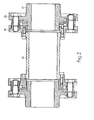
- two hollow shafts 1, 2 are coupled to one another via two similar couplings 3, 4, which are connected to one another via a sleeve 5. Since the two clutches 3, 4 have the same structure, only the clutch 3 will be described in detail below.
- a connecting flange 6 is fastened to the hollow shaft 1 by means of screw bolts 7.
- a conical fit 8 is provided for centering the connecting flange 6 on the hollow shaft 1.
- the connecting flange 6 is opposite a connecting flange 9 of the connecting sleeve 5.
- a plate pack ring 10 Arranged between the two connecting flanges 6, 9 is a plate pack ring 10, which is composed of individual plate packs.
- the plate pack ring 10 arranged at a distance between the flanges 6, 9 is alternately connected to one and the other flange 6, 9 by means of screw bolts 11.
- the flange 6 is formed at the opposite point with play relative to the bolt nut 12.
- the sleeve 5 does not become without a guide in the area of the coupling 3, the sleeve 5 has an extension 13 which projects into the area of the connecting flange 6.
- FIG. 2 differs from the embodiment of FIG. 1 only in that the associated connecting flange 26 is not screwed onto the shaft 21, but is molded on, but the connecting flange 29 associated with the sleeve 25 is screwed on.
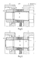
- the shaft 14 of the clamping bolt 11 is conical.
- the inner bore of an adapter sleeve 15 seated on the shaft 14 is correspondingly conical.
- the clamping sleeve has on the side facing the bolt nut 12 as a spacer ring for the slats package wreath 10 serving collar 16.
- the adapter sleeve 15 extends through the annular disc pack 10 into the bore of the connecting flange 6.
- the clamping sleeve 15 is externally cylindrical.
- the bores 18, 19 in the connecting flange 6 and in the disk pack rim 10 are also cylindrical.
- the execution according to Fi g . 4 differs from that of FIG. 3 only in that the clamping sleeve 35 does not protrude into the region of the connecting flange 6.
- the bore 38 in the connecting flange 6 is itself conical.
- FIG. 5 differs from that of FIG. 3 only in that the spacer ring 37 is integrally connected as a collar to the clamping bush 39 and the other spacer ring (36) is not designed as a molded collar, but as an independent washer.
- a separate clamping sleeve 31 is provided in the area of the connecting flange 6, which is cylindrical on the inside and conical on the outside, so that it cooperates as a clamping cone with the correspondingly conical bore in the connecting flange 9.
- FIG. 7 corresponds to the embodiment of FIG. 3 with regard to the connection of the lamellar ring 10 to the connection flange.
- the adjacent connection flanges 46, 49 carry coaxial, overlapping sleeve-shaped projections 41, 42, between which seals act in the manner of piston rings 43 are used. This measure is intended to prevent air from escaping from the space between the flanges, which is associated with disturbing noises.
- a further seal 44 is provided between the screw connection and the corresponding clearance 45 in the connecting flange 39. In this way, the entire plate pack is virtually sealed off from the outside and air vortex losses are avoided.
Landscapes
- Engineering & Computer Science (AREA)
- General Engineering & Computer Science (AREA)
- Mechanical Engineering (AREA)
- Clamps And Clips (AREA)
- Connection Of Plates (AREA)
- Load-Engaging Elements For Cranes (AREA)
- Coating With Molten Metal (AREA)
- Heat Treatment Of Steel (AREA)
- Bolts, Nuts, And Washers (AREA)
- Mutual Connection Of Rods And Tubes (AREA)
- Tents Or Canopies (AREA)
- Joints Allowing Movement (AREA)
Abstract
Description
- Die Erfindung bezieht sich auf eine flexible Ganzstahl-Wellenkupplung mit einem Anschlußflansch für jede der beiden Kupplungshälften und einer zwischen und mit axialem Abstand von den beiden Anschlußflanschen angeordneten und mit Spannbolzen in Umfangsrichtung wechselweise mit dem einen oder anderen Anschlußflansch verbundenen, federelastischen Lamellenpaketkranz, wobei der Lamellenpaketkranz auf Spannbüchsen der Spannbolzen sitzt und zwischen Distanzringen zusammem mit dem Anschlußflansch verspannt ist.
- Solche Kupplungen werden einzeln oder auch paarweise hintereinander geschaltet zur Übertragung von Drehmomenten eingesetzt. Als Einzelkupplung läßt sie einen Winkel und Axialversatz und als Kupplungspaar sogar zusätzlich einen Parallelversatz des Antriebs gegenüber dem Antrieb zu.
- Damit solche Kupplungen mit hohen Drehzahlen betrieben werden können, sind große Anstrengungen gemacht worden, um Unwuchten schon bei der Montage zu vermeiden. Unwuchten werden vor allem durch den Lamellenpaketkranz verursacht. Das gilt nicht nur für einen Lamellenpaketkranz, der sich aus einzelnen Lamellenlaschen zusammensetzt, sondern auch für einen solchen aus Lamellenringen.
- Bei einer bekannten Wellenkupplung der eingangs genannten Art sind zylindrische Paßsitze mit und auch ohne Spannbüchsen mit hoher Paßgenauigkeit zwischen dem Spannbolzen, der Büchse und den Bohrungen im Lamellenpaketkranz einerseits und den Bohrungen im Anschlußflansch andererseits vorgesehen. Solche Paßsitze erfordern sowohl einen hohen Fertigungsaufwand als auch eine sehr sorgfältige und damit auch einen hohen Zeitaufwand erfordernde Montage (DE-AS 26 45 600).
- Um diese Nachteile zu vermeiden, bildet bei einer anderen Wellenkupplung der Lamellenkranz zusammen mit einem damit durch Schraubenbolzen verbundenen Zentrierring ein vormontiertes Paket. Der Zentrierring weist eine fein bearbeitete Umfangsfläche auf, die mit einer entsprechend fein bearbeiteten Umfangsfläche an einem Flansch einen zylindrischen Paßsitz bildet. Diese vormontierte Einheit ist mittels Spannbolzen gegebenenfalls unter Zwischenschaltung von Führungsbüchsen wechselweise an den beiden Flanschen befestigt. Zwar wird bei dieser Wellenkupplung der Lamellenkranz durch den Zentrierring zentriert gehalten, doch sind keine Maßnahmen getroffen, um das fertigungsbedingte Spiel zwischen Spannbolzen und dem Lamellenpaketkranz zu kompensieren. Bei stoßartiger Belastung kann es zu einer Versetzung der Spannbolzen wegen des Spiels kommen, was eine neue Unwucht zur Folge hat.
- Es zeigte sich im Betrieb mit Wellenkupplungen der eingangs genannten Art, daß selbst bei sehr präzise gefertigten Paßsitzen es an den Einspannstellen des Lamellenpaketkranzes zu durch Kerbkorrosion bedingten Brüchen kam.
- Der Erfindung liegt deshalb die Aufgabe zugrunde, eine Wellenkupplung der eingangs genannten Art zu schaffen, die den Einsatz von sowohl aus Laschen als auch aus Ringlamellen bestehenden Lamellenpaketkränzen ermöglicht, die eine Vormontage des Lamellenpaketkranzes nicht erforderlich macht und die schließlich weniger anfällig gegen durch Kerbkorrosion bedingte Brüche ist.
- Diese Aufgabe wird erfindungsgemäß dadurch gelöst, daß der Sitz einer jeden Spannbüchse für den Lamellenpaketkranz auf dem Spannbolzen konisch ausgebildet ist, wobei die axialen Abmessungen des Lamellenpaketkranzes, der Spannringe und der Anschlußflansche einerseits und die der Spannbüchse andererseits sowie die konischen Sitze derart aufeinander abgestimmt sind, daß durch die axiale Spannkraft des Spannbolzens der an den Einspannstellen unter axialer Vorspannung stehende Lamellenkranz am Sitz der wegen des konischen Sitzes beim Vorspannen aufgeweiteten Spannbüchsen zusätzlich unter radialer Vorspannung steht.
- Mit der Erfindung wird auf verhältnismäßig einfache Art und Weise ein absolut spielfreier Sitz des Lamellenpaketkranzes auf den Spannbolzen erzielt, ohne daß es nötig ist, hochpräzise gearbeitete und damit in der Herstellung teure Sitzflächen herzustellen. An jeder Einspannstelle wird durch einen einzigen Spannbolzen sowohl die axiale Vorspannung als auch die radiale Vorspannung im Lamellenpaketkranz erzeugt. Aufgrund der durch die aufgeweitete Spannhülse erzeugten radialen Vorspannung an jeder Einspannstelle ist es im Unterschied zu nicht radial vorgespannten Lamellenpaketkränzen nicht länger möglich, daß sich die Bohrungen in den Lamellen an den Einspannstellen bei in den Lamellen wirkenden Zugnungen ovalförmig aufweiten. Die sonst mit der ovalen Aufweitung verbundene Bewegung der Lamellen an der Einspannstelle und die dadurch verursachte, für die Brüche verantwortliche Reibkorrosion tritt also nicht mehr auf. Aufgrund der so erzeugten radialen Vorspannung an den Sitzen der Lamellen verkraftet die Kupplung auch Stoßbelastungen, die sonst zu einer Verlagerung der Lamellen und damit auch zu Unwuchten führten. Schließlich ist bei der Erfindung die Montage gegenüber anderen Kupplungen vereinfacht. Ohne Vormontage mit zusätzlichen Zentrierringen und ohne hochpräzise gearbeitete zylindrische Sitze kann sie an Ort und Stelle durchgeführt werden.
- Die Herstellung eines spielfreien Sitzes zwischen dem Spannbolzen und dem jeweiligen Anschlußflansch ist weniger kritisch als die Herstellung des Sitzes im Bereich des Lamellenpaketes. Gleichwohl ist es auch an dieser Stelle von Vorteil, wenn der Sitz zwischen dem Spannbolzen und dem jeweiligen Anschlußflansch gegebenenfalls zusammen mit einer Spannbüchse als Spannkonus ausgebildet ist.
- Nach einer weiteren Ausgestaltung sollten die konischen Sitze im Bereich des Lamellenpaketes zwischen der Spannbüchse und dem Spannbolzen vorgesehen sein, weil sich an dieser Stelle die konischen Sitze leichter herstellen lassen als zwischen der Spannbüchse und den Bohrungen des Lamellenpaketes. In entsprechender Weise sind die konischen Sitze im Bereich des jeweiligen Anschlußflansches zwischen der Spannbüchse und den Spannbolzen vorgesehen. Es ist aber auch möglich, an dieser Stelle die konischen Sitze zwischen der Spannbüchse und den Bohrungen des Anschlußflansches vorzusehen.
- Zur Erleichterung der Montage aber auch der Demontage sollten die konischen Sitze im Bereich des Lamellenpaketes und der Anschlußflansche einen unterhalb der Selbsthemmung liegenden Neigungswinkel haben. Vorzugsweise sollten sie an beiden Sitzen denselben Neigungswinkel haben.
- Sofern sowohl im Bereich des Lamellenpaketes als auch im Bereich des jeweiligen Anschlußflansches eine Spannbüchse vorgesehen ist, können diese beiden Spannbüchsen zu einer durchgehenden Spannbüchse vereinigt sein. Die auf den Lamellenkranz ausgeübte Zentrierwirkung kann weiter dadurch verbessert werden, daß die Lochkreise der Anschlußflansche etwas größer als die zugehörigen Lochkreise des Lamellenpaketkranzes sind. Auf diese Art und Weise wird auch in Umfangsrichtung der Lamellen eine Vorspannung erzeugt. Besonders bei Lamellenlaschen werden dadurch Längenunterschiede ausgeglichen.
- Im folgenden wird die Erfindung anhand einer Zeichnung, die verschiedene Ausführungsbeispiele darstellt, näher erläutert.
- Im einzelnen zeigen:
- Fig. 1 zwei gleiche, hintereinander geschaltete und Hohlwellen miteinander verbindende Wellenkupplungen im Axialschnitt,
- Fig. 2 zwei gleiche, hintereinander geschaltete und zwei Hohlwellen miteinander verbindende Wellenkupplungen im Axialschnitt in einer zu Fig. 1 abgewandelten Ausführung,
- Fig. 3 die Verbindungsstelle eines Lamellenpaketkranzes an einem Anschlußflansch im Axialschnitt in einer ersten Ausführung,
- Fig. 4 den Gegenstand gemäß Fig. 3 in einer zweiten Ausführung,
- Fig. 5 den Gegenstand gemäß Fig. 3 in einer dritten Ausführung,
- Fig. 6 den Gegenstand gemäß Fig. 3 in einer vierten Ausführung und
- Fig. 7 den Gegenstand gemäß Fig. 3 in einer fünften Ausführung.
- Gemäß Fig. 1 sind zwei Hohlwellen 1, 2 über zwei gleichartige Kupplungen 3, 4, die miteinander über eine Hülse 5 verbunden sind, miteinander gekuppelt. Da die beiden Kupplungen 3, 4 den gleichen Aufbau haben, wird im folgenden nur die Kupplung 3 in ihren Einzelheiten beschrieben.
- An der Hohlwelle 1 ist ein Anschlußflansch 6 mittels Schraubenbolzen 7 befestigt. Zur Zentrierung des Anschlußflansches 6 auf der Hohlwelle 1 ist ein konischer Paßsitz 8 vorgesehen. Dem Anschlußflansch 6 liegt ein Anschlußflansch 9 der Verbindungshülse 5 gegenüber. Zwischen den beiden Anschlußflanschen 6, 9 ist ein Lamellenpaketkranz 10 angeordnet, der sich aus einzelnen Laschenpaketen zusammensetzt. Der mit Abstand zwischen den Flanschen 6, 9 angeordnete Lamellenpaketkranz 10 ist mittels Schraubenbolzen 11 wechselweise an dem einen und anderen Flansch 6, 9 angeschlossen. Wie der Zeichnung zu entnehmen ist, ist bei Befestigung des Lamellenkranzes 10 mittels des Schraubenbolzens 11 an dem Anschlußflansch 9 der Flansch 6 an der gegenüberliegenden Stelle mit Spiel gegenüber der Bolzenmutter 12 ausgebildet.
- Damit bei einem Bruch der Kupplung 3 die Hülse 5 nicht führungslos im Bereich der Kupplung 3 wird, weist die Hülse 5 einen Ansatz 13 auf, der bis in den Bereich des Anschlußflansches 6 ragt.
- Das Ausführungsbeispiel der Fig. 2 unterscheidet sich von dem Ausführungsbeispiel der Fig. 1 nur dadurch, daß an der Welle 21 der zugehörige Anschlußflansch 26 nicht angeschraubt ist, sondern angeformt ist, dafür aber der der Hülse 25 zugehörige Anschlußflansch 29 angeschraubt ist.
- Gemäß Fig. 3 ist der Schaft 14 des Spannbolzens 11 konisch ausgebildet. Die Innenbohrung einer auf dem Schaft 14 sitzenden Spannhülse 15 ist entsprechend konisch ausgebildet. Die Spannhülse weist auf der der Bolzenmutter 12 zugewandten Seite einen als Distanzring für den Lamellenpaketkranz 10 dienenden Kragen 16 auf. Auf der gegenüberliegenden Seite des Lamellenpaketkranzes 10 zwischen diesem und dem benachbarten Anschlußflansch 6 sitzt auf der Spannhülse 15 ein Distanzring 17. Die Spannhülse 15 ragt durch den Lamellenpaketkranz 10 bis in die Bohrung des Anschlußflansches 6. Die Spannhülse 15 ist außen zylindrisch. Zylindrisch sind auch die Bohrungen 18, 19 im Anschlußflansch 6 und im Lamellenpaketkranz 10.
- Beim Spannen der Spannbolzen wird die Spannhülse 15 radial aufgeweitet. Eventuelle Toleranzen zwischen der Spannhülse 15 und den Bohrungen 18, 19 des Anschlußflansches 6 und des Lamellenpaketkranzes 10 werden ausgeglichen und sogar eine Vorspannung erzeugt. Stoßbelastungen, übertragen von Drehmomenten können deshalb nicht länger eine Versetzung der einzelnen Teile und damit eine neue Unwucht der Wellenkupplung bewirken.
- Die Ausführung gemäß Fig. 4 unterscheidet sich von der der Fig. 3 nur dadurch, daß die Spannhülse 35 nicht bis in den Bereich des Anschlußflansches 6 hineinragt. Bei-dieser Ausführung ist die Bohrung 38 im Anschlußflansch 6 selbst konisch ausgebildet.
- Das Ausführungsbeispiel gemäß Fig. 5 unterscheidet sich von dem der Fig. 3 lediglich darin, daß der Distanzring 37 als Kragen einstückig mit der Spannbüchse 39 verbunden ist und der andere Distanzring (36) nicht als angeformter Kragen ausgebildet ist, sondern als selbständige Ringscheibe.
- Beim Ausführungsbeispiel der Fig. 6, das im Bereich der Spannbüchse 35 dem der Fig. 4 entspricht, ist im Bereich des Anschlußflansches 6 eine separate Spannbüchse 31 vorgesehen, die innen zylindrisch und außen konisch ist, so daß sie als Spannkonus mit der entsprechend konisch gestalteten Bohrung im Anschlußflansch 9 zusammenwirkt.
- Das Ausführungsbeispiel der Fig. 7 entspricht bezüglich des Anschlusses des Lamellenkranzes 10 an den Anschlußflansch dem Ausführungsbeispiel der Fig. 3. Die benachbarten Anschlußflansche 46, 49 tragen jedoch koaxiale, einander überlappende hülsenförmige Ansätze 41., 42, zwischen denen nach Art von Kolbenringen wirkende Dichtungen 43 eingesetzt sind. Durch diese Maßnahme soll verhindert werden, daß aus dem Raum zwischen den Flanschen Luft nach außen entweicht, was mit störenden Geräuschen verbunden ist. Zusätzlich ist eine weitere Dichtung 44 zwischen der Schraubverbindung und der entsprechenden mit Spiel gestalteten Bohrung 45 im Anschlußflansch 39 vorgesehen. Auf diese Art und Weise wird das gesamte Lamellenpaket praktisch nach außen abgeschottet und Luftwirbelverluste vermieden.
Claims (9)
dadurch gekennzeichnet,
daß der Sitz einer jeden Spannbüchse (15,35,39) für den Lamellenpaketkranz (10) auf dem Spannbolzen (11) konisch ausgebildet ist, wobei die axialen Abmessungen des Lamellenpaketkranzes (10), der Spannringe (16,17,36,37) sowie die konischen Sitze derart aufeinander abgestimmt sind, daß durch die axiale Spannkraft des Spannbolzens (11) der an den Einspannstellen unter axialer Vorspannung stehende Lamellenpaketkranz (10) am Sitz der wegen des konischen Sitzes beim Vorspannen aufgeweiteten Spannbüchsen (15,35,39) zusätzlich unter radialer Vorspannung steht.
dadurch gekennzeichnet,
daß der Sitz zwischen dem Spannbolzen (11) und dem jeweiligen Anschlußflansch (6, 9, 26, 29) gegebenenfalls zusammen mit einer Spannbüchse (15, 31, 39, 46, 49) als Spannkonen ausgebildet sind.
dadurch gekennzeichnet,
daß die konischen Sitze im Bereich des Lamellenpaketes (10) zwischen der Spannbüchse (15, 35, 39) und dem Spannbolzen (11) vorgesehen sind.
dadurch gekennzeichnet,
daß die konischen Sitze im Bereich des jeweiligen Anschlußflansches (6, 9, 36, 39) zwischen der Spannbüchse (15, 35, 39)und dem Spannbolzen (11) vorgesehen sind.
dadurch gekennzeichnet,
daß die konischen Sitze im Bereich des Lamellenpaketes (10) und der Anschlußflansche (6, 9,26,29,46,49) einen unterhalb der Selbsthemmung liegenden Neigungswinkel haben.
dadurch gekennzeichnet,
daß die konischen Sitze im Bereich des Lamellenpaketes (10) und der Anschlußflansche (6, 9,26,29,46,49) denselben Neigungswinkel haben.
dadurch gekennzeichnet,
daß für die konischen Sitze im Bereich des Lamellenpaketes (10) und der Anschlußflansche (6, 9, 26, 29, 46, 49) jeweils eine durchgehende Spannbüchse (15, 39) vorgesehen ist.
dadurch gekennzeichnet,
daß die konischen Sitze im Bereich der Anschlußflansche (6 in Fig. 4) zwischen dem Anschlußflansch (6) und den Spannbolzen (11) vorgesehen sind.
dadurch gekennzeichnet,
daß die Lochkreise der Anschlußflansche (6, 9, 26, 29, 46, 49) etwas größer als die zugehörigen Lochkreise des Lamellenpaketkranzes (10) sind.
Priority Applications (1)
| Application Number | Priority Date | Filing Date | Title |
|---|---|---|---|
| AT85114513T ATE38269T1 (de) | 1984-11-29 | 1985-11-15 | Flexible ganzstahl-wellenkupplung. |
Applications Claiming Priority (2)
| Application Number | Priority Date | Filing Date | Title |
|---|---|---|---|
| DE19843443485 DE3443485A1 (de) | 1984-11-29 | 1984-11-29 | Flexible ganzstahl-kupplung |
| DE3443485 | 1984-11-29 |
Publications (2)
| Publication Number | Publication Date |
|---|---|
| EP0184051A1 true EP0184051A1 (de) | 1986-06-11 |
| EP0184051B1 EP0184051B1 (de) | 1988-10-26 |
Family
ID=6251440
Family Applications (1)
| Application Number | Title | Priority Date | Filing Date |
|---|---|---|---|
| EP85114513A Expired EP0184051B1 (de) | 1984-11-29 | 1985-11-15 | Flexible Ganzstahl-Wellenkupplung |
Country Status (6)
| Country | Link |
|---|---|
| US (1) | US4708692A (de) |
| EP (1) | EP0184051B1 (de) |
| JP (1) | JPH0674813B2 (de) |
| AT (1) | ATE38269T1 (de) |
| BR (1) | BR8505964A (de) |
| DE (1) | DE3443485A1 (de) |
Cited By (5)
| Publication number | Priority date | Publication date | Assignee | Title |
|---|---|---|---|---|
| DE3822207C1 (de) * | 1988-07-01 | 1989-10-26 | Rexnord Antriebstechnik Zweigniederlassung Der Rexnord Gmbh, 4600 Dortmund, De | |
| FR2751586A1 (fr) * | 1996-07-23 | 1998-01-30 | Roland Man Druckmasch | Arbre porte-lame de pliage d'un cylindre de pliage |
| EP0816703A3 (de) * | 1996-06-25 | 1998-09-16 | ATEC-Weiss GmbH & Co. KG | Konusschraubverbindung für Lamellenpaket-Wellenkupplungen |
| EP2565481A1 (de) * | 2011-08-29 | 2013-03-06 | Siemens Aktiengesellschaft | Lamellenkupplung |
| WO2016096576A1 (de) * | 2014-12-19 | 2016-06-23 | Rexnord Gmbh | Kupplungselement und kupplungsanordnung zur axialen drehmomentübertragung, und lamellenanordnung für solche |
Families Citing this family (34)
| Publication number | Priority date | Publication date | Assignee | Title |
|---|---|---|---|---|
| US4768992A (en) * | 1986-10-20 | 1988-09-06 | Zurn Industries, Inc. | Flexible drive coupling with convoluted links |
| DE3641547C1 (de) * | 1986-12-05 | 1988-07-14 | Atec Weiss Kg | Flexible Ganzstahl-Wellenkupplung |
| JPH0191126U (de) * | 1987-12-09 | 1989-06-15 | ||
| DE3827673C1 (de) * | 1988-08-16 | 1990-01-18 | Atec-Weiss Kg, 4426 Vreden, De | |
| JPH0399232U (de) * | 1990-01-31 | 1991-10-16 | ||
| DE4315861C2 (de) * | 1993-05-12 | 1995-05-24 | Atec Weiss Gmbh & Co Kg | Flexible Ganzstahlwellenkupplung |
| US5465804A (en) * | 1994-04-25 | 1995-11-14 | T. B. Wood's Sons Company | Combination of a power steering pump and air conditioning compressor in an automotive vehicle |
| EP0702164B1 (de) * | 1994-09-14 | 1998-10-14 | Rexnord Corporation | Veränderbares Gelenk zur Übertragung des Drehmomentes |
| CH688657A5 (de) * | 1994-11-14 | 1997-12-31 | Geislinger Co Schwingungstechn | Trockenkupplung. |
| DE29522078U1 (de) * | 1995-01-25 | 1999-09-30 | Atec-Weiss GmbH & Co KG, 48691 Vreden | Ganzstahlkupplung für Axialkraftübertragung |
| DE29604608U1 (de) * | 1996-03-12 | 1996-05-02 | Chr. Mayr Gmbh + Co Kg, 87665 Mauerstetten | Drehsteife, biegeelastische Wellenkupplung, insbesondere aus Ganzstahl |
| DE29623369U1 (de) | 1996-06-25 | 1998-04-02 | Atec-Weiss GmbH & Co KG, 48691 Vreden | Konusschraubverbindung für Lamellenpaket-Wellenkupplungen |
| DE19724772B4 (de) * | 1997-06-12 | 2004-02-12 | Airbus Deutschland Gmbh | Flexible Kupplung für die Wellen eines von einer zentralen Antriebseinheit angetriebenen Transmissionssystems in Luftfahrzeugen |
| US6074122A (en) * | 1997-12-15 | 2000-06-13 | Caterpillar Inc. | Cone drive power train connection |
| DE19839400A1 (de) | 1998-08-29 | 2000-03-09 | Atec Weiss Gmbh & Co Kg | Flexible Ganzstahl-Wellenkupplung |
| US6199449B1 (en) * | 1998-09-03 | 2001-03-13 | Jeffery M. Harrington | Bicycle crank system |
| US6155742A (en) * | 1999-03-17 | 2000-12-05 | Precision Mechinery Research & Development Center | Coupling mechanism for interconnecting a rotatable connecting end of a support on a broaching machine and a bit holder |
| WO2002055896A1 (en) * | 2001-01-11 | 2002-07-18 | British Autogard Limited | Flexible coupling |
| DE10119427A1 (de) * | 2001-04-20 | 2002-10-24 | Enron Wind Gmbh | Kopplungsvorrichtung für eine Windkraftanlage |
| US6685570B2 (en) * | 2002-01-22 | 2004-02-03 | Kop-Flex | Plate adapter for flexible half couplings |
| US7235014B2 (en) * | 2004-01-21 | 2007-06-26 | Weber Aircraft Lp | Flexible couplings |
| US20060211501A1 (en) * | 2005-03-18 | 2006-09-21 | Rexnord Industries, Inc. | Unitized disc pack and disc pack coupling formed therewith |
| US7559845B2 (en) * | 2005-10-07 | 2009-07-14 | Rexnord Industries, Llc | Nested disc pack coupling |
| DE102006009594A1 (de) * | 2006-03-02 | 2007-09-13 | Chr. Mayr Gmbh + Co Kg | Drehsteife biegeelastische Wellenkupplung, insbesondere Ganzstahlkupplung |
| DE102007035199A1 (de) | 2007-07-25 | 2009-02-05 | Atec-Weiss Gmbh & Co Kg | Flexible Wellenkupplung mit Lamellenpaket und Formschlusselementen |
| JP4901686B2 (ja) * | 2007-10-12 | 2012-03-21 | 株式会社酒井製作所 | 軸継ぎ手 |
| JP6162471B2 (ja) * | 2013-04-30 | 2017-07-12 | 株式会社東芝 | フランジ結合用構造およびフランジ結合方法 |
| JP6143839B1 (ja) * | 2015-12-25 | 2017-06-07 | 株式会社ツバキE&M | 軸継手及び軸継手の軸への取付方法 |
| EP3385558B1 (de) | 2017-04-07 | 2019-12-04 | Flender GmbH | Lamellenkupplung |
| CN112368485B (zh) * | 2018-08-09 | 2023-03-28 | 伊格尔工业股份有限公司 | 联轴器 |
| CN112128259B (zh) * | 2020-09-21 | 2021-08-13 | 株洲时代新材料科技股份有限公司 | 一种橡胶衬套联轴器 |
| CN112576637A (zh) * | 2020-12-21 | 2021-03-30 | 冀凯河北机电科技有限公司 | 一种大扭矩弹性联轴器的简易结构 |
| US20220214047A1 (en) * | 2021-01-06 | 2022-07-07 | Bsh Home Appliances Corporation | Household cooking appliance including a non-welded oven cavity having a seal allowing pyrolytic cleaning |
| CN115095608B (zh) * | 2022-07-08 | 2024-04-09 | 株洲时代新材料科技股份有限公司 | 一种用于风电联轴器的复合金属膜片组件 |
Citations (6)
| Publication number | Priority date | Publication date | Assignee | Title |
|---|---|---|---|---|
| US1454087A (en) * | 1918-05-06 | 1923-05-08 | George H Thomas | Flexible coupling |
| CH471980A (fr) * | 1967-03-15 | 1969-04-30 | Turboflex Ltd | Accouplement flexible |
| CH472594A (fr) * | 1967-03-15 | 1969-05-15 | Turboflex Ltd | Accouplement flexible |
| CH472595A (fr) * | 1967-03-15 | 1969-05-15 | Turboflex Ltd | Accouplement flexible |
| US4073161A (en) * | 1975-06-04 | 1978-02-14 | Flexibox Limited | Flexible couplings |
| GB2065828A (en) * | 1979-12-18 | 1981-07-01 | Orsiflex Ltd | Flexible couplings |
Family Cites Families (8)
| Publication number | Priority date | Publication date | Assignee | Title |
|---|---|---|---|---|
| DE264560C (de) * | ||||
| FR877499A (fr) * | 1940-10-04 | 1942-12-08 | Transmission élastique | |
| US2431409A (en) * | 1944-03-09 | 1947-11-25 | Marley Company Inc | Flexible coupling |
| GB1327775A (en) * | 1970-08-26 | 1973-08-22 | Gib Precision Ltd | Flexible couplings |
| US4019346A (en) * | 1974-02-13 | 1977-04-26 | Kanto Special Steel Works Ltd. | Flexible coupling for rotating shafts |
| US4055966A (en) * | 1975-10-10 | 1977-11-01 | Rexnord, Inc. | Torque transmission coupling |
| JPS5899524U (ja) * | 1981-12-26 | 1983-07-06 | 株式会社デンソー | 軸継手装置 |
| DE8414654U1 (de) * | 1984-05-14 | 1984-08-02 | Voith-Turbo Gmbh & Co Kg, 7180 Crailsheim | Drehsteife, beugeelastische wellenkupplung |
-
1984
- 1984-11-29 DE DE19843443485 patent/DE3443485A1/de active Granted
-
1985
- 1985-11-15 AT AT85114513T patent/ATE38269T1/de not_active IP Right Cessation
- 1985-11-15 EP EP85114513A patent/EP0184051B1/de not_active Expired
- 1985-11-26 US US06/801,883 patent/US4708692A/en not_active Expired - Lifetime
- 1985-11-28 BR BR8505964A patent/BR8505964A/pt not_active IP Right Cessation
- 1985-11-29 JP JP60267572A patent/JPH0674813B2/ja not_active Expired - Fee Related
Patent Citations (6)
| Publication number | Priority date | Publication date | Assignee | Title |
|---|---|---|---|---|
| US1454087A (en) * | 1918-05-06 | 1923-05-08 | George H Thomas | Flexible coupling |
| CH471980A (fr) * | 1967-03-15 | 1969-04-30 | Turboflex Ltd | Accouplement flexible |
| CH472594A (fr) * | 1967-03-15 | 1969-05-15 | Turboflex Ltd | Accouplement flexible |
| CH472595A (fr) * | 1967-03-15 | 1969-05-15 | Turboflex Ltd | Accouplement flexible |
| US4073161A (en) * | 1975-06-04 | 1978-02-14 | Flexibox Limited | Flexible couplings |
| GB2065828A (en) * | 1979-12-18 | 1981-07-01 | Orsiflex Ltd | Flexible couplings |
Cited By (11)
| Publication number | Priority date | Publication date | Assignee | Title |
|---|---|---|---|---|
| DE3822207C1 (de) * | 1988-07-01 | 1989-10-26 | Rexnord Antriebstechnik Zweigniederlassung Der Rexnord Gmbh, 4600 Dortmund, De | |
| EP0349672A1 (de) * | 1988-07-01 | 1990-01-10 | Rexnord Antriebstechnik | Flexible Wellenkupplung mit je einem Anschlussflansch für den Anbau weiterer Kupplungsteile |
| US5019015A (en) * | 1988-07-01 | 1991-05-28 | Rexnord Antriebstechnik Zweigniederlassung Der Rexnord Gesellschaft Mbh | Flexible shaft coupling |
| EP0816703A3 (de) * | 1996-06-25 | 1998-09-16 | ATEC-Weiss GmbH & Co. KG | Konusschraubverbindung für Lamellenpaket-Wellenkupplungen |
| FR2751586A1 (fr) * | 1996-07-23 | 1998-01-30 | Roland Man Druckmasch | Arbre porte-lame de pliage d'un cylindre de pliage |
| GB2315482A (en) * | 1996-07-23 | 1998-02-04 | Roland Man Druckmasch | Folding |
| US5873808A (en) * | 1996-07-23 | 1999-02-23 | Man Roland Druckmaschinen Ag | Folding blade shaft of a folding cylinder |
| GB2315482B (en) * | 1996-07-23 | 2001-02-14 | Roland Man Druckmasch | Folding blade shaft of a folding cylinder |
| EP2565481A1 (de) * | 2011-08-29 | 2013-03-06 | Siemens Aktiengesellschaft | Lamellenkupplung |
| WO2016096576A1 (de) * | 2014-12-19 | 2016-06-23 | Rexnord Gmbh | Kupplungselement und kupplungsanordnung zur axialen drehmomentübertragung, und lamellenanordnung für solche |
| US10359079B2 (en) | 2014-12-19 | 2019-07-23 | Rexnord Gmbh | Coupling element and coupling assembly for axial torque transmission, and disc assembly therefor |
Also Published As
| Publication number | Publication date |
|---|---|
| BR8505964A (pt) | 1986-07-29 |
| DE3443485A1 (de) | 1986-06-05 |
| JPH0674813B2 (ja) | 1994-09-21 |
| JPS61192931A (ja) | 1986-08-27 |
| ATE38269T1 (de) | 1988-11-15 |
| EP0184051B1 (de) | 1988-10-26 |
| US4708692A (en) | 1987-11-24 |
| DE3443485C2 (de) | 1989-02-16 |
Similar Documents
| Publication | Publication Date | Title |
|---|---|---|
| EP0184051B1 (de) | Flexible Ganzstahl-Wellenkupplung | |
| EP0462991B1 (de) | Biegeelastisches kupplungselement und verfahren zu dessen herstellung | |
| DE4304611C2 (de) | Wellenkupplung | |
| DE19625318C2 (de) | Konusschraubverbindung für Lamellenpaket-Wellenkupplungen | |
| EP0349672A1 (de) | Flexible Wellenkupplung mit je einem Anschlussflansch für den Anbau weiterer Kupplungsteile | |
| DE3230932C2 (de) | Kupplung | |
| EP0132567B1 (de) | Spannvorrichtung für einen Schleifring | |
| DE2257903C3 (de) | Ringförmiges, elastisches Element zur Verbindung zweier Kupplungsflansche | |
| DE4308910A1 (de) | Bremsscheibe für Scheibenbremsen, insbesondere Radbremsscheibe für Schienenfahrzeuge | |
| DE3109388A1 (de) | "hochelastische wellenkupplung" | |
| DE3245041C2 (de) | Schwingungstilgeranordnung im Antriebsstrang von Kraftfahrzeugen | |
| DE2604669C3 (de) | Wellenkupplung | |
| WO2021219328A1 (de) | Bewegliche doppelkupplung zum versatzausgleichenden verbinden zweier wellen | |
| EP1318313B1 (de) | Verbindungsvorrichtung | |
| DE4315861C2 (de) | Flexible Ganzstahlwellenkupplung | |
| DE102006049665B4 (de) | Kupplung für eine Kardanwelle | |
| EP0425769B1 (de) | Elastische Kupplung zur Drehmoment-Übertragung | |
| DE2741652C2 (de) | Drehsteife, elastisch beugefähige Wellenkupplung | |
| DE2017149A1 (de) | Spannsatz zur Verbindung von Wellen mit Nabenkörpern | |
| DE69001100T2 (de) | Antriebsuebertragung fuer ein kfz mit elektromagnetischen bremsvorrichtungen. | |
| DE8434950U1 (de) | Flexible Ganzstahl-Kupplung | |
| EP0724087A1 (de) | Ganzstahlkupplung für Axialkraftübertragung | |
| EP0283828B1 (de) | Kupplung | |
| DE1165941B (de) | Spannsatz zur Verbindung einer Nabe mit einer Welle | |
| DE9302185U1 (de) | Wellenkupplung |
Legal Events
| Date | Code | Title | Description |
|---|---|---|---|
| PUAI | Public reference made under article 153(3) epc to a published international application that has entered the european phase |
Free format text: ORIGINAL CODE: 0009012 |
|
| AK | Designated contracting states |
Kind code of ref document: A1 Designated state(s): AT BE CH FR GB IT LI LU NL SE |
|
| 17P | Request for examination filed |
Effective date: 19860628 |
|
| 17Q | First examination report despatched |
Effective date: 19871001 |
|
| GRAA | (expected) grant |
Free format text: ORIGINAL CODE: 0009210 |
|
| ITF | It: translation for a ep patent filed | ||
| AK | Designated contracting states |
Kind code of ref document: B1 Designated state(s): AT BE CH FR GB IT LI LU NL SE |
|
| REF | Corresponds to: |
Ref document number: 38269 Country of ref document: AT Date of ref document: 19881115 Kind code of ref document: T |
|
| GBT | Gb: translation of ep patent filed (gb section 77(6)(a)/1977) | ||
| ET | Fr: translation filed | ||
| PLBE | No opposition filed within time limit |
Free format text: ORIGINAL CODE: 0009261 |
|
| STAA | Information on the status of an ep patent application or granted ep patent |
Free format text: STATUS: NO OPPOSITION FILED WITHIN TIME LIMIT |
|
| 26N | No opposition filed | ||
| ITTA | It: last paid annual fee | ||
| EPTA | Lu: last paid annual fee | ||
| EAL | Se: european patent in force in sweden |
Ref document number: 85114513.6 |
|
| REG | Reference to a national code |
Ref country code: GB Ref legal event code: IF02 |
|
| PGFP | Annual fee paid to national office [announced via postgrant information from national office to epo] |
Ref country code: SE Payment date: 20021111 Year of fee payment: 18 Ref country code: LU Payment date: 20021111 Year of fee payment: 18 |
|
| PG25 | Lapsed in a contracting state [announced via postgrant information from national office to epo] |
Ref country code: LU Free format text: LAPSE BECAUSE OF NON-PAYMENT OF DUE FEES Effective date: 20031115 |
|
| PG25 | Lapsed in a contracting state [announced via postgrant information from national office to epo] |
Ref country code: SE Free format text: LAPSE BECAUSE OF NON-PAYMENT OF DUE FEES Effective date: 20031116 |
|
| EUG | Se: european patent has lapsed | ||
| PGFP | Annual fee paid to national office [announced via postgrant information from national office to epo] |
Ref country code: NL Payment date: 20041118 Year of fee payment: 20 |
|
| PGFP | Annual fee paid to national office [announced via postgrant information from national office to epo] |
Ref country code: GB Payment date: 20041119 Year of fee payment: 20 Ref country code: FR Payment date: 20041119 Year of fee payment: 20 Ref country code: CH Payment date: 20041119 Year of fee payment: 20 |
|
| PGFP | Annual fee paid to national office [announced via postgrant information from national office to epo] |
Ref country code: AT Payment date: 20041125 Year of fee payment: 20 |
|
| PGFP | Annual fee paid to national office [announced via postgrant information from national office to epo] |
Ref country code: BE Payment date: 20041209 Year of fee payment: 20 |
|
| PG25 | Lapsed in a contracting state [announced via postgrant information from national office to epo] |
Ref country code: GB Free format text: LAPSE BECAUSE OF EXPIRATION OF PROTECTION Effective date: 20051114 |
|
| PG25 | Lapsed in a contracting state [announced via postgrant information from national office to epo] |
Ref country code: NL Free format text: LAPSE BECAUSE OF EXPIRATION OF PROTECTION Effective date: 20051115 |
|
| BE20 | Be: patent expired |
Owner name: *ATEC-WEISS K.G. Effective date: 20051115 |
|
| REG | Reference to a national code |
Ref country code: GB Ref legal event code: PE20 |
|
| REG | Reference to a national code |
Ref country code: CH Ref legal event code: PL |
|
| NLV7 | Nl: ceased due to reaching the maximum lifetime of a patent |
Effective date: 20051115 |
|
| BE20 | Be: patent expired |
Owner name: *ATEC-WEISS K.G. Effective date: 20051115 |