EP0184161A2 - Verfahren und Gerät zum fotografischen Setzen eines Nachformmodells für die Herstellung von Stempeln - Google Patents
Verfahren und Gerät zum fotografischen Setzen eines Nachformmodells für die Herstellung von Stempeln Download PDFInfo
- Publication number
- EP0184161A2 EP0184161A2 EP85115198A EP85115198A EP0184161A2 EP 0184161 A2 EP0184161 A2 EP 0184161A2 EP 85115198 A EP85115198 A EP 85115198A EP 85115198 A EP85115198 A EP 85115198A EP 0184161 A2 EP0184161 A2 EP 0184161A2
- Authority
- EP
- European Patent Office
- Prior art keywords
- image
- window
- suitably
- transparent
- master
- Prior art date
- Legal status (The legal status is an assumption and is not a legal conclusion. Google has not performed a legal analysis and makes no representation as to the accuracy of the status listed.)
- Withdrawn
Links
- 238000000034 method Methods 0.000 title claims abstract description 22
- 238000004519 manufacturing process Methods 0.000 title claims abstract description 13
- 239000012780 transparent material Substances 0.000 claims abstract description 8
- 230000009466 transformation Effects 0.000 claims description 17
- 230000003287 optical effect Effects 0.000 claims description 7
- 238000005266 casting Methods 0.000 claims description 3
- 238000005286 illumination Methods 0.000 description 5
- 239000000463 material Substances 0.000 description 4
- 238000012546 transfer Methods 0.000 description 3
- 238000000844 transformation Methods 0.000 description 3
- 238000005452 bending Methods 0.000 description 2
- 230000000694 effects Effects 0.000 description 2
- 229920002972 Acrylic fiber Polymers 0.000 description 1
- 230000015572 biosynthetic process Effects 0.000 description 1
- 238000004040 coloring Methods 0.000 description 1
- 238000013461 design Methods 0.000 description 1
- 238000011161 development Methods 0.000 description 1
- 238000005498 polishing Methods 0.000 description 1
- 238000012545 processing Methods 0.000 description 1
- 230000011514 reflex Effects 0.000 description 1
- 239000000126 substance Substances 0.000 description 1
Images


Classifications
-
- B—PERFORMING OPERATIONS; TRANSPORTING
- B41—PRINTING; LINING MACHINES; TYPEWRITERS; STAMPS
- B41B—MACHINES OR ACCESSORIES FOR MAKING, SETTING, OR DISTRIBUTING TYPE; TYPE; PHOTOGRAPHIC OR PHOTOELECTRIC COMPOSING DEVICES
- B41B13/00—Equipment specially adapted for photographing mounted characters or the like, e.g. advertisements, lines
Definitions
- the invention relates to a process for producing by photo setting a master for the production of stamps or the like of a suitably text like image set along generally straight base line whereby the image is geometrically transformed via a substantially curved mirror surface of a transparent rod like body, said mirror surface forming an inclined angle in relation to said image, so that the master will comprise the corresponding image in a distorted curved form.
- the invention also relates to an apparatus for carrying out the image transformation process.
- the invention gives a method for processing an image in connection with graphical reproduction into an image having a desired and preferably curved form which deviates from the basic form of the image.
- the setting machines can be mechanical so that one with the aid of the typewriting keyboard mechanically or in some other way controls the mounting of character lines along a more or less straight base line.
- These character lines are formed as lines of separate elements comprising character types with a printing surface the plane of which is distinct from the base plane of the line so that it is possible to produce cliches against this line for example with the aid of casting.
- the produced cliches are then used for printing the character lines in a printing press or the like.
- the above mentioned setting-up procedure can of course be performed also manually which often is necessary when special effects are desired.
- photo-setting is based on the principle that material which is sensitive e.g. to light beams is illuminated in such a way that the difference between the plane of the printing surface and the base plane at the illumination appears as illuminated and non-illuminated parts, respectively, whereafter suitable treatment such as a chemical, electrical or electrochemical treatment results in that the planes of illuminated and non-illuminated will lie on different levels.
- suitable treatment such as a chemical, electrical or electrochemical treatment results in that the planes of illuminated and non-illuminated will lie on different levels.
- the photo-setting master which provides illumination in a form which corresponds to the characters which are desired to be set.
- the problem with the distortion of the geometrical configuration of the character lines is solved by applying at a transparent part of the circumference of the said body and suitably along support line extending around the body the image in the form of one or several character lines set on an at least partially transparent material, after which the character line is illuminated from the outside, and the distorted image reflected through said body via the suitably conical mirror surface towards the end plane of said body is reproduced.
- said reproduction is further treated with photometric methods to form a master for the production of stamps or alike.
- the invention applies to the principle of applying the image adjacent to a surface and reflecting the original image via a reflecting surface which is biased to the image surface onto viewing plane whereby the reflecting surface is formed so that it corresponds to the desired form of the image in such a way that the radius for the intersectional lines between the reflecting surface and planes parallel to the viewing plane stand in desired relationship to the distance from said planes to the viewing plane.
- the reflecting surface is a mirror surface which preferably consists of the reflecting inner surface surface in a transparent body.
- the kind of transformation in each partial area of the mirror depends on the curve radius of ) the reflecting surface within this area as well as of the angle of the mirror surface in relation to the image surface and the viewing plan.
- different kinds of transformations In the following will be illustrated especially embodiments wherein the trans-5 formation takes place from images especially of a straight and longish character but also other embodiments will be evident to those skilled in the art.
- the invention is described below especially with a prismatic embodiment whereby the image surface preferably corresponds to a first window in the prism and the viewing plane corresponds to second window whereas the remaining outer surfaces of the prism preferably are not transparent.
- prismatic embodiments is here to be understood subsatntially rodlike prisms with the reflecting area applied to one end of the rod.
- a conical mirror is provided against the second window whereby the apparatus preferably is formed as a prismatic body of circular cross section.
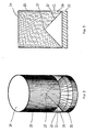
- the invention is now to its principle described with reference to the general prismatic block according to fig. 1.
- the block comprises an outer surface of which a part, limited for example by the line 2, at the same time forms a first window surface 3.
- the block further comprises a mirror surface 4 and a second window surface 5.
- the intersectional line 6 of the mirror surface 4 with the first window surface 3 is curved, and the intersectional line 7 with the second window surface 5 likewise.
- the cross section forms a triangel, wherein the intersection with the window surfaces forms shorter sides 8, 9 and the intersection with the mirror surface forms the longest side 10.
- the original image is at least partly transparent so that it can be illuminated from the outside towards the window surface 3 and thus illuminated can be seen through window 5.
- the image to be transformed is placed adjacent to window surface 3 and preferably directly in contact with the same. Thereafter the image is illuminated from the outside and the distorted image which can be seen via the reflecting surface 4 through the second window surface 5 is reproduced e.g. by photographing, photo setting or in some other way. In order to obtain completely exact reproduction it is important that the illumination is quite even. With uneven illumination one can obtain special effect and accentuate certain parts of the image.
- the form of the mirror surface 4 can be characterized by its intersectional lines 6, 7, 7' with the planes for the window surface 3 and planes 5' parallel with a viewing plane which preferably consists of window surface 5.
- a viewing plane which preferably consists of window surface 5.
- the transformation of the image depends on the curve radius of the mirror surface 4 within each partial area as well as of the angle ⁇ between the mirror surface 4 and the viewing plane which in Fig. 1 is depicted equal to the window 5.
- the angle « always is the same a continous image is obtained while the changing of the angle in certain cases may lead to discontinuity in the transformed image.
- An angle of about 45° between the mirror surface and the viewing plane have proved especially advantageous for avoiding discontinuities.
- the original image is a straight line in a plane parallel with the viewing plane 5 said line is reproduced in accordance with the illustrated embodiment in the viewing plane 5 as curved in a direction towards the intersectional line 7.
- This fact leads to a special embodiment of the invention with which embodiment it is possible to transform a straight line into a circle and a linear image into a circular one.
- This embodiment is illustrated by Fig. 2 and its cross section in Fig 3.
- the said embodiment is characterized in that the first contact window 3 is formed of the outer surface 11 of a transparent cylinder, whereby the mirror surface 4 is formed of a conical surface 12 situated inside the cylinder surface 11 and having its top 13 directed towards the viewing plane 5, which in the illustrated case is a plane perpendicular to the cylinder wall 11.
- the top angle of the mirror cone 12 is about 80 to 100°, preferably close to 90°.
- the embodiment of the invention which is depicted in Figs 2 and 3 is suitably produced from a rod of transparent material, whereby the viewing plane 5 is formed by one end face 14 of the rod while the other end face comprises an inwards tapering conical surface 12.
- the cylinder wall includes a preferably dark non-transparent surface structure in the areas which do not form the window 11.
- An apparatus of the above described kind may easily be produced by turning and polishing from a variety of transparent materials such as e.g. acrylic plastic.
- a series of characters on a substantially straight base line such as a text intended for a circular stamp, is applied on a partly transparent material such as paper.
- the paper strip is is wound around the cylinder wall 11 with the character series against the window 5.
- the paper strip may be provided with guiding marks 16 marking a base line wheras the cylinder wall 11 is provided with corresponding guiding marks such as guide lines 19 to facilitate the placing of the base line parallel with the viewing plane 5.
- the positioning is further facilitated if the prismatic body is provided with an extension 20 which does not take part in the the optical transformation but provides a support for the character strip as it is placed against the cylinder wall 11.
- This extension 20 is preferably made of non-transparent material in order to avoid extra reflexions upon the reflecting cone surface 12.
Landscapes
- Lenses (AREA)
- Length Measuring Devices By Optical Means (AREA)
- Illuminated Signs And Luminous Advertising (AREA)
- Light Sources And Details Of Projection-Printing Devices (AREA)
Applications Claiming Priority (2)
| Application Number | Priority Date | Filing Date | Title |
|---|---|---|---|
| FI844713A FI78572C (sv) | 1984-11-30 | 1984-11-30 | Förfarande och anordning för brytning av ljus vid grafisk återgivning |
| FI844713 | 1984-11-30 |
Publications (2)
| Publication Number | Publication Date |
|---|---|
| EP0184161A2 true EP0184161A2 (de) | 1986-06-11 |
| EP0184161A3 EP0184161A3 (de) | 1988-02-24 |
Family
ID=8519987
Family Applications (1)
| Application Number | Title | Priority Date | Filing Date |
|---|---|---|---|
| EP85115198A Withdrawn EP0184161A3 (de) | 1984-11-30 | 1985-11-29 | Verfahren und Gerät zum fotografischen Setzen eines Nachformmodells für die Herstellung von Stempeln |
Country Status (3)
| Country | Link |
|---|---|
| EP (1) | EP0184161A3 (de) |
| DE (1) | DE184161T1 (de) |
| FI (1) | FI78572C (de) |
Cited By (1)
| Publication number | Priority date | Publication date | Assignee | Title |
|---|---|---|---|---|
| DE3718586A1 (de) * | 1987-06-03 | 1988-12-22 | Kunststoffe Dattenberg Gmbh | Vorrichtung zur herstellung eines rundsatzes |
Family Cites Families (5)
| Publication number | Priority date | Publication date | Assignee | Title |
|---|---|---|---|---|
| BE561937A (de) * | ||||
| US2314272A (en) * | 1941-01-24 | 1943-03-16 | Grudin Louis | Apparatus for photographically reproducing display type lines and the like |
| US3558225A (en) * | 1967-05-22 | 1971-01-26 | Kurt Kirchhoff | Optical photo opposing apparatus |
| DE2134785C3 (de) * | 1971-07-12 | 1974-05-30 | Berthold Fototype Gmbh, 8000 Muenchen | Titelsetzgerät mit Verzerreinrichtung |
| US4326775A (en) * | 1979-02-07 | 1982-04-27 | King Don G | Method for operating a panoramic optical system |
-
1984
- 1984-11-30 FI FI844713A patent/FI78572C/sv not_active IP Right Cessation
-
1985
- 1985-11-29 DE DE1985115198 patent/DE184161T1/de active Pending
- 1985-11-29 EP EP85115198A patent/EP0184161A3/de not_active Withdrawn
Cited By (1)
| Publication number | Priority date | Publication date | Assignee | Title |
|---|---|---|---|---|
| DE3718586A1 (de) * | 1987-06-03 | 1988-12-22 | Kunststoffe Dattenberg Gmbh | Vorrichtung zur herstellung eines rundsatzes |
Also Published As
| Publication number | Publication date |
|---|---|
| FI78572B (fi) | 1989-04-28 |
| FI844713L (fi) | 1986-05-31 |
| EP0184161A3 (de) | 1988-02-24 |
| DE184161T1 (de) | 1986-11-27 |
| FI78572C (sv) | 1989-08-10 |
| FI844713A0 (fi) | 1984-11-30 |
Similar Documents
| Publication | Publication Date | Title |
|---|---|---|
| US5967032A (en) | Printing process using a thin sheet lenticular lens material | |
| US5201027A (en) | Electronic apparatus for the laser imprinting of screen-process printing stencils and the like | |
| EP0805957B1 (de) | Verfahren und vorrichtung zum gravieren | |
| US3462226A (en) | Preregistration and layout of three-dimensional prints | |
| EP0811487A2 (de) | System zum Aufziehen von Druckplatten und Verfahren zu dessen Anwendung | |
| EP0773105B1 (de) | System zum Aufziehen von Druckplatten, Aufzeichnungsplatte des physischen Registers und Verfahren zu deren Verwendung | |
| US4611539A (en) | Device and method for the precision mounting of flexible printing plates | |
| WO1995019888A1 (en) | Laser-driven silk screen mask device | |
| US4231659A (en) | Method of making an overlay mask and a printing plate therefrom | |
| EP0184161A2 (de) | Verfahren und Gerät zum fotografischen Setzen eines Nachformmodells für die Herstellung von Stempeln | |
| US5661566A (en) | Method for making a plurality of printing plates | |
| US6247404B1 (en) | Method of making newspaper printing plates | |
| US4622591A (en) | Apparatus and method for precisely orienting originals on an image scanner drum | |
| US4705390A (en) | Originals patching device | |
| JP3839083B2 (ja) | レンチキュラプリントに対する画像拡大方法 | |
| US691138A (en) | Process of making pictures. | |
| US4322161A (en) | Stripper's table and method of compositing lithographic work pieces | |
| US4771551A (en) | Method of and apparatus for applying angle data marks to originals for image data scanning | |
| EP0169967A2 (de) | Vorrichtung zur Winkelstellung einer Vorlage für Abtaster | |
| US4168889A (en) | Type carrier for use in photocomposition machines | |
| US3183817A (en) | Changeable typographic make-up system | |
| EP1577114B1 (de) | Vorrichtung zur positionierung einer strahlungsaushärtungsquelle an einem gravierzylinder oder einem gravierplattenhalter | |
| EP0852542B1 (de) | Verbesserte transparente vorrichtung zum messen und herstellungsverfahren | |
| US5148741A (en) | Method and apparatus for reflective enhancement of rotogravure printed material | |
| JPH0416343B2 (de) |
Legal Events
| Date | Code | Title | Description |
|---|---|---|---|
| PUAI | Public reference made under article 153(3) epc to a published international application that has entered the european phase |
Free format text: ORIGINAL CODE: 0009012 |
|
| AK | Designated contracting states |
Kind code of ref document: A2 Designated state(s): AT BE CH DE FR GB IT LI NL SE |
|
| ITCL | It: translation for ep claims filed |
Representative=s name: BUGNION S.P.A. |
|
| TCAT | At: translation of patent claims filed | ||
| TCNL | Nl: translation of patent claims filed | ||
| EL | Fr: translation of claims filed | ||
| DET | De: translation of patent claims | ||
| PUAL | Search report despatched |
Free format text: ORIGINAL CODE: 0009013 |
|
| AK | Designated contracting states |
Kind code of ref document: A3 Designated state(s): AT BE CH DE FR GB IT LI NL SE |
|
| 17P | Request for examination filed |
Effective date: 19880812 |
|
| 17Q | First examination report despatched |
Effective date: 19900301 |
|
| STAA | Information on the status of an ep patent application or granted ep patent |
Free format text: STATUS: THE APPLICATION IS DEEMED TO BE WITHDRAWN |
|
| 18D | Application deemed to be withdrawn |
Effective date: 19900712 |
|
| RIN1 | Information on inventor provided before grant (corrected) |
Inventor name: BECKER, KAJ BERNHARD Inventor name: LOENNQVIST, KURT HENRIK |