EP0184313B1 - Transfusionsflasche für Flüssigkeiten - Google Patents
Transfusionsflasche für Flüssigkeiten Download PDFInfo
- Publication number
- EP0184313B1 EP0184313B1 EP85307809A EP85307809A EP0184313B1 EP 0184313 B1 EP0184313 B1 EP 0184313B1 EP 85307809 A EP85307809 A EP 85307809A EP 85307809 A EP85307809 A EP 85307809A EP 0184313 B1 EP0184313 B1 EP 0184313B1
- Authority
- EP
- European Patent Office
- Prior art keywords
- bottle
- barrel portion
- ribs
- liquid
- liquid transfusing
- Prior art date
- Legal status (The legal status is an assumption and is not a legal conclusion. Google has not performed a legal analysis and makes no representation as to the accuracy of the status listed.)
- Expired
Links
- 239000007788 liquid Substances 0.000 title claims description 63
- 230000007423 decrease Effects 0.000 claims description 10
- 239000000463 material Substances 0.000 claims description 9
- -1 polypropylene Polymers 0.000 claims description 4
- 239000004698 Polyethylene Substances 0.000 claims description 2
- 229920000573 polyethylene Polymers 0.000 claims description 2
- 229920000915 polyvinyl chloride Polymers 0.000 claims description 2
- 239000004800 polyvinyl chloride Substances 0.000 claims description 2
- 239000004743 Polypropylene Substances 0.000 claims 1
- 229920001155 polypropylene Polymers 0.000 claims 1
- 238000007599 discharging Methods 0.000 description 16
- 238000005259 measurement Methods 0.000 description 4
- 229920003002 synthetic resin Polymers 0.000 description 4
- 239000000057 synthetic resin Substances 0.000 description 4
- 238000013022 venting Methods 0.000 description 4
- 238000005452 bending Methods 0.000 description 3
- 239000011521 glass Substances 0.000 description 3
- 230000007257 malfunction Effects 0.000 description 3
- 238000004891 communication Methods 0.000 description 2
- 239000000243 solution Substances 0.000 description 2
- WQZGKKKJIJFFOK-GASJEMHNSA-N Glucose Natural products OC[C@H]1OC(O)[C@H](O)[C@@H](O)[C@@H]1O WQZGKKKJIJFFOK-GASJEMHNSA-N 0.000 description 1
- 239000007864 aqueous solution Substances 0.000 description 1
- 239000000428 dust Substances 0.000 description 1
- 230000005489 elastic deformation Effects 0.000 description 1
- 239000008103 glucose Substances 0.000 description 1
- 239000008187 granular material Substances 0.000 description 1
- 230000001788 irregular Effects 0.000 description 1
- 230000001737 promoting effect Effects 0.000 description 1
- 150000003839 salts Chemical class 0.000 description 1
- XLYOFNOQVPJJNP-UHFFFAOYSA-N water Substances O XLYOFNOQVPJJNP-UHFFFAOYSA-N 0.000 description 1
Images



Classifications
-
- A—HUMAN NECESSITIES
- A61—MEDICAL OR VETERINARY SCIENCE; HYGIENE
- A61J—CONTAINERS SPECIALLY ADAPTED FOR MEDICAL OR PHARMACEUTICAL PURPOSES; DEVICES OR METHODS SPECIALLY ADAPTED FOR BRINGING PHARMACEUTICAL PRODUCTS INTO PARTICULAR PHYSICAL OR ADMINISTERING FORMS; DEVICES FOR ADMINISTERING FOOD OR MEDICINES ORALLY; BABY COMFORTERS; DEVICES FOR RECEIVING SPITTLE
- A61J1/00—Containers specially adapted for medical or pharmaceutical purposes
- A61J1/14—Details; Accessories therefor
-
- A—HUMAN NECESSITIES
- A61—MEDICAL OR VETERINARY SCIENCE; HYGIENE
- A61J—CONTAINERS SPECIALLY ADAPTED FOR MEDICAL OR PHARMACEUTICAL PURPOSES; DEVICES OR METHODS SPECIALLY ADAPTED FOR BRINGING PHARMACEUTICAL PRODUCTS INTO PARTICULAR PHYSICAL OR ADMINISTERING FORMS; DEVICES FOR ADMINISTERING FOOD OR MEDICINES ORALLY; BABY COMFORTERS; DEVICES FOR RECEIVING SPITTLE
- A61J1/00—Containers specially adapted for medical or pharmaceutical purposes
- A61J1/05—Containers specially adapted for medical or pharmaceutical purposes for collecting, storing or administering blood, plasma or medical fluids ; Infusion or perfusion containers
Definitions
- the present invention relates to a liquid transfusing bottle and more particularly to an improvement in a liquid transfusing bottle made of synthetic resin in which liquid to be transfused, such as glucose solution, physiological aqueous solution of salt, Ringer's solution or the like, is contained.
- a hitherto known liquid transfusing bottle of the above-mentioned type is generally constructed in the form of a glass bottle with a rubber plug fitted thereto.
- the conventional glass bottle has been generally replaced in recent years with a liquid transfusing bottle (hereinafter referred to simply as bottle) made of synthetic resin.
- bottle made of synthetic resin. It is true that the problems concerning breakage, for example when the bottle drops on the floor and reduced dead weight of the bottle have been resolved by employing synthetic resin but there is still a necessity to use an air venting needle adapted to be pierced through the rubber plug or the bottom wall.
- the air venting needle is intended to inhibit flow of liquid to be transfused (hereinafter referred to simply as liquid) under the influence of negative pressure in the bottle which is caused as the liquid is consumed therefrom. For this reason there exists a problem that dust or foreign material in the air may be introduced into the interior of the bottle together with air as the latter flows through the air venting needle.
- the bottle is so constructed that the outer wall is flexibly deformed to reduce its diameter in conformance with the consumption of liquid and thereby the internal volume of the bottle decreases correspondingly.
- DE-A-2754120 discloses a liquid transfusing container which is provided with short lines of folding weakness which permit folding and facilitate collapse of the container. These lines of folding weakness do not however assist in controlling uniform deformation of the container during discharge of a liquid.
- the present invention has been made whereby a flexible liquid transfusing bottle is provided which assures that the bottle is uniformly deformed in the form of diameter reduction during discharge of liquid to be transfused without any malfunction such as distortion, irregular bending, breakage of the bottle or the like.
- Another object of the present invention is to provide a liquid transfusing bottle which assures that discharging of liquid is smoothly effected at a substantially constant speed for a short period of time in such a manner that the ratio of discharge speed is determined more than 75% when the bottle is suspended at a height of 50 cm as measured from the position where measurement is carried out and a ratio of discharging speed is determined more than 85% when it is suspended at a height of 75 cm as measured from the position where measurement is carried out.
- a liquid transfusing bottle made of flexible material including a barrel portion, a shoulder portion at the upper end of said barrel portion, and a bottom portion at the lower end of said barrel portion, said barrel portion having a flattened configuration with a front barrel portion and a rear barrel portion which are located opposite to one another in the direction of shorter diameter with respect to a cross-sectional plane, and side walls which are located opposite to one another in a direction of a longer diameter with respect to said cross-sectional plane and comprise sides of said front barrel portion and said rear barrel portion, said barrel portion being deformable and having a substantially symmetrical structure relative to an imaginary plane in which an imaginary parting line respectively extends along a middle part of both of the side walls in a longitudinal direction thereof, and deformation guiding parts formed relative to the side walls at a predetermined area with respect to the longitudinal direction of the bottle, characterised in that each of said side walls defines a substantially flat side extending from the shoulder portion to the bottom portion, and said side walls are parallel to each
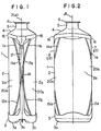
- reference numeral 1 generally represents a liquid transfusing bottle (hereinafter referred to simply as bottle).
- the bottle 1 is made of transparent or semitransparent flexible material, for instance, polyethylene, polyvinylchloride or the like and comprises a barrel portion 2, a bottom portion 3, a shoulder portion 4, a nozzle portion 5 and an opening 6.
- the barrel portion 2 is designed in the flattened geometrical configuration having a longer diameter and a shorter diameter as seen in the cross-sectional plane, for instance, cylindrical configuration shaped in the substantially elliptical cross-sectional contour which is scribed in the symmetrical relation both in the vertical direction as well as in the transverse direction.
- the lower end of the barrel portion 2 is closed with the bottom portion 3, whereas the upper end part of the same is constituted by the shoulder portion 4 of which diameter as seen in both the directions decreases radically.
- the shoulder portion 4 is integrally formed with the nozzle portion 5 having a substantially reduced diameter at the position located above the former and the opening 6 is constituted by the upper end of the nozzle portion 5.
- the opening 6 is adapted to tightly receive a plug made of rubber through which a hollow needle is pierced to take the content of the bottle from the interior of the latter.
- Parting lines 7 and 8 are disposed on both the side walls of the bottle located opposite to one another as seen in the direction of longer diameter, while extending along the imaginary center line which passes in the center area as defined by each of the side walls whereby they serve as boundary line for both the front barrel portion 2a and the rear barrel portion 2b.
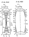
- the bottle 1 includes deformation guiding parts each of which has a contour substantially symmetrical relative to the imaginary center line. In the illustrated embodiment it includes pairs of ribs on both the sides of the parting line 7 in such a manner that the latter is interposed therebetween.
- ribs 11 a and 12a are formed on the surface of the front barrel portion 2a located on the one side relative to the parting line 7
- ribs 11 b and 12b are formed on the surface of the rear barrel portion 2b located on the other side relative to the parting line 7.
- the ribs 11a and 11 b as well as the ribs 12a and 12b are located symmetrical relative to the plane a which extends through the parting lines 7 and 8.
- the upper ends of the ribs 11 a and 11 b are located at the position in the proximity of the shoulder portion 4, whereas the lower ends of the same are oriented downwardly at a certain inclination angle toward the center point M which is located at the middle as seen in the direction of extension of the parting line 7.
- both the ribs 11a a and 11b come closer to the parting line 7 as they extend downwardly.
- the lower ends of the ribs 12a and 12b are located in the proximity of the bottom portion 3, whereas the upper ends of the same are oriented upwardly at a certain inclination angle toward the center point M.
- both the ribs 12a and 12b come closer to the parting line 7 as they extend upwardly.
- ribs 14a and 15a are formed on the surface of the front barrel portion 2a located on the one side relative to the parting line 8. As is apparent from Fig. 2, the ribs 14a and 15a are located symmetrically to the ribs 11a and 12a relative to the plane ⁇ which is defined by the shorter diameter of the transverse plane. Further, another ribs are formed at the position located symmetrical to the ribs 14a and 15a relative to the plane a on the surface of the rear barrel portion 2b on the other side of the parting line 8.
- junction portion 16 as defined between the upper part of the barrel portion 2 and the shoulder portion 4 is designed to have a diameter appreciably larger than that of the barrel portion 2 with the exception of the area located in the vicinity of the parting lines 7 and 8.
- the diameter of the bottom portion 3 is determined appreciably larger than that of the lower end of the barrel portion 2 with the exception of the area located in the vicinity of the parting lines 7 and 8.
- the lowermost surface of the bottom portion 3 has a recessed part 3c extending along the larger diameter which is raised upwardly toward the barrel portion 2 as seen in the drawing.
- parts 3a and 3b located on both the sides of the part 3c serve as a standing foot.
- the barrel portion 2 has flat planes 17 having a predetermined width W extending in parallel with the center lines 7 and 8 which are located at the center thereof with the exception of the area where they intersect the ribs.
- the bottle 1a may be so modified that a horizontal rib 18 is bridged between both the ribs 11a and 11b and another horizontal rib 21 is bridged between both the ribs 12a and 12b, as shown in Figs. 3(a) and (b).
- the bottle 1 may be so modified that an additional horizontal rib 22 extends in parallel with the horizontal rib 18 in the area as defined between both the ribs 11 a and 11b and another additional horizontal rib 23 extends in parallel with the horizontal rib 21 in the area as defined between both the ribs 12a and 12b, as shown in Figs. 4(a) and (b).
- all the ribs are designed in the groove-shaped configuration, that is, concave configuration, as seen in the cross-sectional plane.
- the present invention is not limited to this arrangement.
- they may be designed in the projection-shaped configuration, that is, convex configuration as seen in the cross-sectional plane.
- the bottle 1 is filled with liquid to be transfused and a plug made of rubber or the like material is then airtightly fitted to the opening of the bottle. Thereafter, a hollow needle is pierced through the thus airtightly fitted plug whereby communication is established between the interior of the bottle and the outside of the latter. Now, liquid in the bottle is ready to be discharged therefrom through the hollow needle while it is supported in the upside-down state.
- areas 20a and 20b have a wide surface area, discharge of liquid is smoothly carried out at a high speed as they deform inwardly, without any malfunction such as distortion of the bottle, breakage or the like. Subsequently deformation is gradually carried out in such a manner that the central area of the areas 20a and 20b come closer to one another. As they come closer to one another increasingly, the bottom portion 3 is caused to bend about the recessed part 3c which extends along the longer diameter thereof whereby both the parts 3a and 3b located on both the sides of the recessed part 3c come closer to one another. This allows both the portions 20a and 20b to come to one another sufficiently.
- the bottle of the invention has flat planes 17 having a predetermined width W with the parting lines 7 and 8 located at the middle of the latter on both the sides thereof, they serve as contact surface relative to the adjacent bottle when a number of bottles are transported by means of a belt conveyor or the like.
- transportation is successfully carried out with the minimal occurrence of deviation of some bottle from the conveyor line.
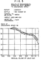
- Figs. 5 and 6 graphically illustrate a number of measured ratios of discharging speed with respect to three samples of bottle with ribs formed thereon in accordance with the first embodiment of the invention as shown in Figs. 1 and 2 as well as three samples of conventional bottle with no rib formed thereon.
- the bottle of the invention has a ratio of discharging speed higher than that of the conventional one from the time point when a residual volume of liquid amounts to about 300 cc
- the bottle of the invention has a ratio of discharge speed of about 75% at the time point when a residual volume of liquid amounts to 50 cc while the conventional one has a ratio of discharge speed of about 60% at the same time point
- the bottle of the invention has a ratio of discharge speed of about 70% at the time point when a residual amount of liquid amounts to about zero while the conventional one has a ratio of discharge speed of about 50% at the same time point.
- parting lines 7 and 8 extend in the vertical direction at the middle of both the side walls of the barrel portion 2 of the bottle 1 which are located opposite to one another in the direction of longer diameter and they serve as a boundary between the front barrel portion 2a and the rear barrel portion 2b.
- the recessed parts 24 as defined by points A, B, C, D, E and C in the polygonal contour is formed on both the sides of the parting line 7 in the symmetrical relation relative to the latter as seen in Fig. 7.
- the side walls of the bottle 1 are designed in the slightly curved configuration and therefore the area as defined by the points A, B, C, D, E and C is a three dimentional symmetrical figure relative to the plane a which extends through the parting lines 7 and 8. Thus, they are recognized as polygonal figure when they are seen from the side.
- the polygonal figure as defined by the points A, B, C, D, E and C is constituted by two isosceles triangles ABC and DEC which are connected to one another at the point C in the X-shaped pattern while their bottom lines are connected at the same point to build a single straight line.
- the points A and B are located just below the shoulder portion 4, the points D and E are located just above the bottom portion 3 and the point C is located at the middle of the parting line 7 as seen in the vertical direction.
- the contour of the recessed parts is designed in such a manner that the distance as measured from the shoulder portion downwardly as well as the distance as measured from the bottom portion upwardly decrease gradually as the measured position is located away from the parting line 7.
- the depth of the recessed parts 24 is determined, for instance, about 1 mm in the case of a bottle 1 which has a capacity of 820 ml (as measured at time when overflow occurs).
- Each of the recessed parts 24 is lowered from the other part but its surface does not exhibit a uniform curved plane.
- a part of the recessed area 24 as identified by reference numeral 26 which is flush with the band-shaped area having a width W with the parting line 7 located at the middle thereof exhibits a flat plane.
- the area 26 serves as contact surface at which the adjacent bottles come in contact when they are transported by means of a belt conveyor or the like. Thus, transportation is carried out without any occurrence of deviation of some bottles away from the conveyor line during operation of transportation.
- recessed parts 25 are formed on both the sides of the parting line 8 in the same manner as in the foregoing case.
- a part 3c extending along the longer diameter on the lowermost surface of the bottom portion 3 is recessed upwardly towards the center of the bottle and parts 3a and 3b located on both the sides of the part 3C serve as a standing foot.
- the bottle 1 is filled with liquid to be transfused and a plug made of rubber or the like material is then airtightly fitted to the opening of the bottle. Thereafter, a hollow needle is pierced through the thus airtightly fitted plug whereby communication is established between the interior of the bottle and the outside of the same. Now, liquid in the bottle is ready to be discharged therefrom through the hollow needle while it is suspended from the above in the upside-down state.
- center area 20a and 20b have a wide surface area, inward deformation is carried out without any malfunction such as distortion of the bottle, breakage or the like.
- liquid is smoothly discharged at a high speed and thereby the center parts of the areas 20a and 20b are gradually deformed to the flattened configuration in such a manner that they come closer to one another.
- the bottom portion 3 is caused to bend about the recessed part 3c which extends along the longer diameter thereof whereby both the parts 3a and 3b located on both the sides of the recessed part 3c come closer to one another. This allows both the areas 20a and 20b to come close to one another sufficiently.
- the shoulder portion 4 is deformed to the flattened configuration in conformance with deformation of the recessed parts of the barrel portion, resulting in the substantially whole volume of liquid in the bottle being discharged, therefrom. This means that discharge of liquid is achieved at a predetermined high speed for a short period of time.
- the boundary between the recessed parts 24 and 25 and the areas 20a and 20b is subjected to bending by two times with a distance of about 1 mm held between both the ends thereof.
- each of the ribs constituting a boundary is subjected to bending by four times in the foregoing embodiment.
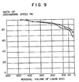
- a ratio of discharging speed as represented by (discharging speed-initial discharging speedx100) was measured with respect to samples of bottle in accordance with the second embodiment of the invention and graphs as shown in Fig. 9 was obtained as a result of measurements.
- Fig. 9 shows graphs representing a ratio of discharging speed measured with respect to two samples of bottle in accordance with the second embodiment of the invention in which water is filled as transfusion liquid, wherein each of the samples is designed to have the same dimensions and configuration as those of the bottle in accordance with the first embodiment of the invention (by means of which graphs in Fig. 5 are prepared).
- Fig. 9 As will be readily apparent from a comparison of Fig. 9 with Fig. 5, there is a remarkable difference therebetween. Specifically, with respect to the bottle as shown in Fig. 5 which has a capacity of 475 cc it is found that a ratio of discharge speed instantaneously exceeds 100% in the area where a residual volume of liquid amounts to 475 cc to 150 cc and it decreases below 90% in the area where a residual volume of liquid amounts to about 200 cc. This means that the bottle in Fig. 5 has some fluctuation of discharge speed. On the contrary, the bottle in Fig. 9 has a substantially constant ratio of discharging speed in the range of 95 to 100%.
- the ratio decreases smoothly at a uniform rate with fluctuation of discharging speed being hardly recognized. Even in the area where a residual volume of liquid is held less than 150 cc it is confirmed that discharge speed decreases smoothly and as a whole liquid is discharged at a substantially constant speed for a short period of time.
Landscapes
- Health & Medical Sciences (AREA)
- Pharmacology & Pharmacy (AREA)
- Life Sciences & Earth Sciences (AREA)
- Animal Behavior & Ethology (AREA)
- General Health & Medical Sciences (AREA)
- Public Health (AREA)
- Veterinary Medicine (AREA)
- Hematology (AREA)
- Containers Having Bodies Formed In One Piece (AREA)
- Medical Preparation Storing Or Oral Administration Devices (AREA)
Claims (8)
Applications Claiming Priority (4)
| Application Number | Priority Date | Filing Date | Title |
|---|---|---|---|
| JP1984164432U JPH0112823Y2 (de) | 1984-10-30 | 1984-10-30 | |
| JP164432/84U | 1984-10-30 | ||
| JP1985145488U JPH0223300Y2 (de) | 1985-09-24 | 1985-09-24 | |
| JP145488/85U | 1985-09-24 |
Publications (2)
| Publication Number | Publication Date |
|---|---|
| EP0184313A1 EP0184313A1 (de) | 1986-06-11 |
| EP0184313B1 true EP0184313B1 (de) | 1990-02-07 |
Family
ID=26476582
Family Applications (1)
| Application Number | Title | Priority Date | Filing Date |
|---|---|---|---|
| EP85307809A Expired EP0184313B1 (de) | 1984-10-30 | 1985-10-29 | Transfusionsflasche für Flüssigkeiten |
Country Status (4)
| Country | Link |
|---|---|
| US (1) | US4700871A (de) |
| EP (1) | EP0184313B1 (de) |
| KR (1) | KR890004903Y1 (de) |
| CN (1) | CN1011030B (de) |
Families Citing this family (18)
| Publication number | Priority date | Publication date | Assignee | Title |
|---|---|---|---|---|
| WO1989003697A1 (en) * | 1987-10-22 | 1989-05-05 | Leonard Barry French | Collapsible solution container |
| US4943288A (en) * | 1988-02-25 | 1990-07-24 | Bioresearch, Inc. | Liquid reinfusion bag system |
| US4959062A (en) * | 1989-02-23 | 1990-09-25 | C. R. Bard, Inc. | Integrated soft shell reservoir |
| US5083678A (en) * | 1990-08-27 | 1992-01-28 | James River Corporation | Collapsible dispenser bottle |
| WO1993018803A1 (en) * | 1992-03-23 | 1993-09-30 | C.R. Bard, Inc. | Fluid collection container |
| CN101036619A (zh) * | 2006-11-15 | 2007-09-19 | 四川科伦药业股份有限公司 | 一种输液瓶 |
| DE202010012728U1 (de) * | 2010-09-22 | 2011-11-29 | Deutsche Gesellschaft für Humanplasma mbH | Blutplasmasammelflasche |
| KR101741887B1 (ko) | 2012-05-07 | 2017-05-30 | 더 프록터 앤드 갬블 캄파니 | 가요성 용기 |
| BR112016001873A2 (pt) | 2013-08-01 | 2017-08-01 | Procter & Gamble | recipientes flexíveis tendo juntas aprimoradas e métodos para a produção das mesmas |
| EP3027531B1 (de) * | 2013-08-01 | 2017-11-29 | The Procter and Gamble Company | Flexible einwegbehälter mit oberflächenelementen |
| US11156353B2 (en) | 2014-12-01 | 2021-10-26 | #GlowOnTech | Container with illumination source |
| US10694829B1 (en) | 2016-01-30 | 2020-06-30 | Mike Diamonds | Smart container with illumination source |
| US10591138B1 (en) * | 2016-01-30 | 2020-03-17 | Michael Nigel Blackdiamond | Container with internal illumination source |
| CN104398382A (zh) * | 2014-12-22 | 2015-03-11 | 高宏 | 自塑形输液软瓶 |
| WO2016164681A1 (en) * | 2015-04-10 | 2016-10-13 | The Procter & Gamble Company | Flexible containers with intermediate bottom members |
| WO2017039432A1 (en) * | 2015-08-28 | 2017-03-09 | N.V. Nutricia | Collapsible bottle |
| JP6186547B1 (ja) * | 2017-03-07 | 2017-08-23 | 花王株式会社 | シート材容器 |
| CN110141720B (zh) * | 2019-06-21 | 2021-04-27 | 青岛大学附属医院 | 一种手术室输血袋保温加压装置 |
Family Cites Families (10)
| Publication number | Priority date | Publication date | Assignee | Title |
|---|---|---|---|---|
| GB865062A (en) * | 1957-09-24 | 1961-04-12 | Anton Pfrimmer | Container for medicinal liquids |
| US3081002A (en) * | 1957-09-24 | 1963-03-12 | Pfrimmer & Co J | Containers for medicinal liquids |
| DE1090383B (de) * | 1958-02-10 | 1960-10-06 | Braun Fa B | Behaelter fuer biologische Fluessigkeiten, Seren oder Infusionsloesungen |
| FR1356549A (fr) * | 1963-04-26 | 1964-03-27 | Récipient pour la consommation d'un contenu à consistance crémeuse | |
| FR1449600A (fr) * | 1964-09-14 | 1966-05-06 | Fr Des Laboratoires Labaz Soc | Perfectionnements aux flacons en matière souple, notamment pour produits médicamenteux |
| US3921630A (en) * | 1974-02-26 | 1975-11-25 | American Hospital Supply Corp | Thermoplastic bottle with controlled lateral collapse and method of dispensing liquid therefrom |
| US4088166A (en) * | 1974-11-21 | 1978-05-09 | Baxter Travenol Laboratories, Inc. | Molded collapsible solution container having gusset portions |
| CA1079231A (en) * | 1976-12-16 | 1980-06-10 | Baxter Travenol Laboratories | Flexible collapsible container defining relatively rigid shoulder and base at opposite end |
| US4308904A (en) * | 1979-04-09 | 1982-01-05 | Baxter Travenol Laboratories, Inc. | Collapsible solution container having reduced collapse rate at the end of the collapsing process |
| US4553970A (en) * | 1983-12-28 | 1985-11-19 | Miles Laboratories, Inc. | Collapsible molded container |
-
1985
- 1985-10-18 CN CN85107756A patent/CN1011030B/zh not_active Expired
- 1985-10-21 US US06/789,876 patent/US4700871A/en not_active Expired - Fee Related
- 1985-10-29 EP EP85307809A patent/EP0184313B1/de not_active Expired
-
1989
- 1989-05-08 KR KR2019890005997U patent/KR890004903Y1/ko not_active Expired
Also Published As
| Publication number | Publication date |
|---|---|
| KR890004903Y1 (ko) | 1989-07-28 |
| EP0184313A1 (de) | 1986-06-11 |
| CN1011030B (zh) | 1991-01-02 |
| US4700871A (en) | 1987-10-20 |
| CN85107756A (zh) | 1986-09-17 |
Similar Documents
| Publication | Publication Date | Title |
|---|---|---|
| US4700871A (en) | Liquid transfusing bottle | |
| US6311878B1 (en) | Dispensing package for fluent products | |
| US4126249A (en) | Collapsible tubes | |
| EP0408929B1 (de) | Faltbare Kunststoff-Flasche | |
| US6626308B2 (en) | Hermetically sealed container with self-draining closure | |
| EP0854092A2 (de) | Behälter aus wärmeverformbaren und wärmeverschweissbaren Material | |
| US4917257A (en) | Garbage can | |
| PL192458B1 (pl) | Pojemnik o dużej wytrzymałości | |
| US4553970A (en) | Collapsible molded container | |
| US7185790B2 (en) | Hermetically sealed container with non-drip opening | |
| US4330072A (en) | Dispenser with side spout for flowable material | |
| US12280910B2 (en) | Collapsible, hangable plastic bottle | |
| JP2002521177A (ja) | 改良浸漬チューブ付注出ポンプを備える内袋型容器 | |
| US20170247152A1 (en) | Flip-Top Cap | |
| JPH0112823Y2 (de) | ||
| JPS62135149A (ja) | 液体収容容器 | |
| JPH0223300Y2 (de) | ||
| JPH0323245Y2 (de) | ||
| CN210527077U (zh) | 一种带缓流功能的定量瓶 | |
| US4201252A (en) | Non-clogging gravity transfer connector for closed containers | |
| US6145694A (en) | Plug-type barrel | |
| JPH0237783B2 (de) | ||
| JP3019095U (ja) | 排出機構付きシャンプー等容器 | |
| JPH0535648U (ja) | 取り残し残量を低減させるポンプ付き容器 | |
| JPH0752030Y2 (ja) | スクイズ容器 |
Legal Events
| Date | Code | Title | Description |
|---|---|---|---|
| PUAI | Public reference made under article 153(3) epc to a published international application that has entered the european phase |
Free format text: ORIGINAL CODE: 0009012 |
|
| AK | Designated contracting states |
Kind code of ref document: A1 Designated state(s): GB SE |
|
| 17P | Request for examination filed |
Effective date: 19860722 |
|
| 17Q | First examination report despatched |
Effective date: 19870910 |
|
| GRAA | (expected) grant |
Free format text: ORIGINAL CODE: 0009210 |
|
| AK | Designated contracting states |
Kind code of ref document: B1 Designated state(s): GB SE |
|
| PG25 | Lapsed in a contracting state [announced via postgrant information from national office to epo] |
Ref country code: SE Effective date: 19900207 |
|
| PLBE | No opposition filed within time limit |
Free format text: ORIGINAL CODE: 0009261 |
|
| STAA | Information on the status of an ep patent application or granted ep patent |
Free format text: STATUS: NO OPPOSITION FILED WITHIN TIME LIMIT |
|
| 26N | No opposition filed | ||
| PGFP | Annual fee paid to national office [announced via postgrant information from national office to epo] |
Ref country code: GB Payment date: 19931019 Year of fee payment: 9 |
|
| PG25 | Lapsed in a contracting state [announced via postgrant information from national office to epo] |
Ref country code: GB Effective date: 19941029 |
|
| GBPC | Gb: european patent ceased through non-payment of renewal fee |
Effective date: 19941029 |