EP0184329A1 - Compresseurs à air à déplacement positif - Google Patents
Compresseurs à air à déplacement positif Download PDFInfo
- Publication number
- EP0184329A1 EP0184329A1 EP85308024A EP85308024A EP0184329A1 EP 0184329 A1 EP0184329 A1 EP 0184329A1 EP 85308024 A EP85308024 A EP 85308024A EP 85308024 A EP85308024 A EP 85308024A EP 0184329 A1 EP0184329 A1 EP 0184329A1
- Authority
- EP
- European Patent Office
- Prior art keywords
- inlet
- compressor
- valve
- compressed air
- pressure
- Prior art date
- Legal status (The legal status is an assumption and is not a legal conclusion. Google has not performed a legal analysis and makes no representation as to the accuracy of the status listed.)
- Withdrawn
Links
- 238000006073 displacement reaction Methods 0.000 title claims abstract description 9
- 239000000314 lubricant Substances 0.000 claims description 14
- 238000002347 injection Methods 0.000 claims description 9
- 239000007924 injection Substances 0.000 claims description 9
- 239000012530 fluid Substances 0.000 claims description 4
- 238000013022 venting Methods 0.000 claims description 4
- 230000001419 dependent effect Effects 0.000 claims 1
- 230000006835 compression Effects 0.000 description 9
- 238000007906 compression Methods 0.000 description 9
- 238000010276 construction Methods 0.000 description 5
- 238000001514 detection method Methods 0.000 description 1
- 230000009977 dual effect Effects 0.000 description 1
- 239000000203 mixture Substances 0.000 description 1
- 230000000630 rising effect Effects 0.000 description 1
Images
Classifications
-
- F—MECHANICAL ENGINEERING; LIGHTING; HEATING; WEAPONS; BLASTING
- F04—POSITIVE - DISPLACEMENT MACHINES FOR LIQUIDS; PUMPS FOR LIQUIDS OR ELASTIC FLUIDS
- F04C—ROTARY-PISTON, OR OSCILLATING-PISTON, POSITIVE-DISPLACEMENT MACHINES FOR LIQUIDS; ROTARY-PISTON, OR OSCILLATING-PISTON, POSITIVE-DISPLACEMENT PUMPS
- F04C28/00—Control of, monitoring of, or safety arrangements for, pumps or pumping installations specially adapted for elastic fluids
- F04C28/24—Control of, monitoring of, or safety arrangements for, pumps or pumping installations specially adapted for elastic fluids characterised by using valves controlling pressure or flow rate, e.g. discharge valves or unloading valves
-
- F—MECHANICAL ENGINEERING; LIGHTING; HEATING; WEAPONS; BLASTING
- F04—POSITIVE - DISPLACEMENT MACHINES FOR LIQUIDS; PUMPS FOR LIQUIDS OR ELASTIC FLUIDS
- F04C—ROTARY-PISTON, OR OSCILLATING-PISTON, POSITIVE-DISPLACEMENT MACHINES FOR LIQUIDS; ROTARY-PISTON, OR OSCILLATING-PISTON, POSITIVE-DISPLACEMENT PUMPS
- F04C29/00—Component parts, details or accessories of pumps or pumping installations, not provided for in groups F04C18/00 - F04C28/00
- F04C29/0007—Injection of a fluid in the working chamber for sealing, cooling and lubricating
- F04C29/0014—Injection of a fluid in the working chamber for sealing, cooling and lubricating with control systems for the injection of the fluid
Definitions
- the present invention relates to positive displacement compressors, in particular of rotary oil-sealed type, and is concerned with matching the output of such compressor with the demand for compressed air.
- oil-sealed compressor is used herein to designate that type of compressor in which a lubricant is injected into the compression space and is then subsequently removed from the compressed air and recycled.
- valves may be movable between only two positions, that is to say a fully opened position and a fully.closed position, or alternatively the valve may be a so called unloader valve which is progressively controlled by a servo valve in response to a rise of the outlet pressure above the normal working pressure to modulate the inflowing air with the result that as the outlet pressure rises, the inlet is progressively throttled and then finally closed.
- a valve on the compressor inlet results in a power economy at no-load or reduced load conditions but the compressor still consumes a very substantial amount of power since the internal pressure differential accross the compression elements is still above the normal value. It is known, e.g.
- the main lubricant reservoir communicates with an oil injection aperture in the stator by means of a pipe including a pilot operated valve whilst the auxiliary reservoir communicates directly with this aperture.
- the pipe connecting the compressor outlet to the lubricant reservoirs may be selectively vented to the atmosphere by a further pilot controlled valve.
- the various pilot controlled valves are under the control of a pilot which is responsive to the pressure in the main lubricant reservoir. In normal operation, air is drawn in through the inlet and compressed by the rotor/stator unit into which lubricant is injected. The entrained oil is subsequently removed from the air which then passes to an outlet line.
- the pressure in the main reservoir rises and when this exceeds the predetermined pressure the pilot closes the pilot operated valve in the inlet thereby preventing further air from entering the compressor inlet, closes the pilot operated valve in the line connecting the main reservoir to the rotor/stator unit, therby preventing oil from being fed from this reservoir into the compression space, and opens the pilot operated valve communicating with the pipe connecting the stator outlet to the main reservoir thereby connecting the stator outlet to atmosphere.
- the pressure in the compression space i.e. within the stator and the auxiliary lubricant reservoir fall substantially to atmospheric pressure whilst the pressure at the inlet tends to drop to a value somewhat below atmospheric pressure.
- the pressure in the compression space at the oil injection aperture is therefore also slightly subatmospheric and this pressure therefore results in a small volume of oil being drawn from the auxiliary reservoir into the compression space and this volume is sufficient for the needs of the rotor/ stator unit. If the compressed air load should resume, or alternatively if the compressed air load had not in any event fallen to zero, the pressure in the main reservoir progressively falls and.when this becomes less than a further predetermined value, the pilot reverses the positions of the various pilot operated valves and normal operation is resumed.
- This construction is advantageous in that when the compressor is running under no-load conditions, the pressure at the stator outlet is atmospheric and thus the rotor/stator unit absorbs the minimum amount of power, perhaps about 20% of its full rated power.
- the compressor will cycle between normal operation and its idling depressurised operation and this is itself wasteful of power since compressed air in the interior of the stator and the auxiliary reservoir is repeatedly vented to atmosphere and thus must be subsequently repressurised
- the inlet valve is either fully closed or fully open and there is no attempt to match the volume of. air flowing into the stator with the demand for compressed air.
- a positive displacement air compressor has an inlet which includes two or more independently actuable inlet valves in parallel, detecting means for determining whether the rate which air is being compressed exceeds or is less than the compressed air demand to which the compressor is subjected and actuating means controlled by the detecting means for opening and closing each inlet valve independently to vary the rate of air flow through the inlet.
- a rotary positive displacement air compressor includes a stator containing a rotor and having an inlet and an outlet, the inlet having two or more independently actuable inlet valves in parallel, detecting means for detecting the pressure of the compressed air and arranged to produce a signal when the said pressure exceeds or is less than predetermined values thereby indicating whether the rate at which air is being compressed exceeds or is less than the compressed air demand to which the compressor is subjected and actuating means controlled by the detecting means for opening and closing each inlet valve independently to vary the rate of air flow through the inlet.
- inlet valves there are two or more inlet valves arranged in parallel and thus.by opening and closing these in different combinations the rate of airflow into the compressor can be varied without the necessity of providing a valve of conventional unloader valve type, that is to say a valve which may be progressively moved between its open and closed positions so that the rate at which air is compressed may be matched very coarsely to the compressed air demand and whilst the matching is unlikely to be precise any difference could be compensated for, at least in the short term, by providing the compressor with a receiver, that is to say a reservoir for excess compressed air.
- a valve of conventional unloader valve type that is to say a valve which may be progressively moved between its open and closed positions so that the rate at which air is compressed may be matched very coarsely to the compressed air demand and whilst the matching is unlikely to be precise any difference could be compensated for, at least in the short term, by providing the compressor with a receiver, that is to say a reservoir for excess compressed air.
- each inlet valve is associated with an inlet aperture and that the sizesof the inlet apertures differ. Thus if two identical inlet apertures are provided only two different air flow rates into the compressor can be achieved but if the inlet apertures are of a different size three different air flow rates can be achieved. It is preferred that each inlet valve is operated by a fluid that is pressurised by the compressor and in the case of an oil sealed compressor this fluid may constitute oil. -I t is, -however, preferred that the fluid is compressed air.
- the detection as to whether the rate at which air is compressed differs from the demand for compressed air may be effected in various ways but it is preferred that it is effected by measuring the pressure of the compressed air produced since this will rise when the rate of supply exceeds the demand and will fall when demand exceeds supply and thus constitutes a simple means by which the difference between the rates of supply and demand may be detected.
- the detecting means is connected to the control means which in turn is connected to a respective control valve for each inlet valve, the control means being arranged to increase or decrease the open area of the compressor inlet by one increment when the said pressure exceeds or is less than the said values, respectively.
- the control' means will close one of the inlet valves or alternatively close one of the inlet valves and open an inlet valve with a smaller inlet area.
- each valve includes a main piston whose movement is controlled by the associated control valve and an auxiliary piston which is movable under the control of the control means into a position which limits the movement of the associated main piston, the control means being so arranged that when one inlet valve is closed the auxiliary piston of the other inlet valve or valves is positioned to limit the movement of the associated main piston but when all these valves are open the auxiliary pistons are positioned not to limit the movement of the main pistons.
- the main piston of each inlet valve has three positions, that is to say fully open, fully closed and partially open and this is found to be desirable in order to be able accurately to control the rate of air flow through each inlet valve since this will vary in dependence on how many other inlet valves are open.
- the control means when the detecting means indicate that the rate of supply of compressed air exceeds the demand the control means is arranged to decrease the open area of the compressor inlet by one increment but if the demand for compressed air is zero the pressure of the compressed air will rise above the predetermined value and remain there. In this condition the compressor will still consume a substantial amount of energy. It is therefore preferred that the compressor also includes venting means arranged to vent the interior of the stator down to a pressure substantially less than normal working pressure when the demand for compressed air is substantially zero which reduces the amount of energy consumed by the compressor when running on no load.
- the stator inlet communicates with atmosphere via a first pilot operated valve
- the stator outlet is connected to a primary lubricant reservoir via a non-return valve and to an auxiliary lubricant reservoir which is always substantially at atmospheric pressure via a second pilot operated valve
- the compressor includes a lubricant injection orifice connected to the primary reservoir via a third pilot operated valve and to the second reservoir and a pilot control.
- system responsive, in use, to the compressed air load to which the compressor is subjected and arranged to switch the first and third pilot operated valves from an open position to a closed position, and the second pilot operated valve from a closed position to an open position when the compressed air load falls below a predetermined value, e.g. the compressed air load is substantially zero.
- the compressor includes means which vent the stator down to substantially atmospheric pressure when there is no demand.for compressed air, which venting means are generally similar to those disclosed in British Patent No. 1257728 and which are disclosed in more detail in British Patent S p e - ' .cification No.2147363A of the present applicants, the disclosure of which is incorporated herein by reference.
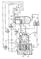
- the compressor is of eccentric rotor sliding vane type and includes a stator 2 within which a rotor 4 is eccentrically rotatably mounted.
- the stator and rotor together define a crescent shaped working space which is divided into working cells by a number, in this case 8, of vanes 6 which are slidably accommodated in a respective longitudinal slot in the rotor.
- the construction and operation of this rotor/stator unit are conventional and will therefore not be described in more detail.
- the stator has an inlet 8, an outlet 10 and one or more oil injection orifices 12 situated between the inlet and the outlet with respect to the intended direction of rotation of the rotor.
- the stator outlet 10 communicates with a primary oil reservoir 14 via a non-return valve 16, the reservoir 14 accommodating a plurality of baffle plates 17 against which the compressed air impinges and a conventional coalescing element 18 and communicating with a supply line 20 via a further non-return valve 22.
- the lower end of the primary reservoir 14 communicates with the oil injection orifices 12 via a line 24 which includes an oil cooler 26 and an oil filter 28, which are conventional and will therefore not be described, and a pilot operated shut-off valve 30.
- the stator inlet 8 is controlled by a pilot operated inlet valve assembly 32 which is accommodated within an inlet housing 36 and will be described in more detail below. Ths stator outlet 10 also communicates with the inlet housing 36 by means of a line 38 which is controlled by a further pilot shut-off valve 40.
- the inlet housing 36 communicates with the atmosphere via a conventional air filter 42, and constitutes a secondary or auxiliary oil reservoir the base of which communicates with the oil injection orifices 12 via a line 44 which includes a non-return valve 46 and the oil filter 28 which is common to the lines 24.and 44.
- the compressor also includes a pilot control system comprising a pressure sensitive switch assembly 50 which communicates with the supply line 20 downstream of the valve 22 and is thus responsive to the pressure within the primary reservoir in normal operation
- the switch assembly is also connected to a microprocessor based control unit 52 which controls the position of four solenoid valves, as will be discussed below.
- the inlet valve assembly 32 comprises a first valve which controls an inlet aperture 60 and a second valve which controls an inlet aperture 62 whose area is half that of the aperture 60.
- the first valve comprises a main piston 64 which cooperates with the aperture 60 and acts against a spring 66 and is actuated by a compressed air line 68 and an auxiliary piston 70 which is actuated by a compressed air line 72 and whose movement is limited by a stop 74.
- the second valve similarly comprises a main piston 76 which cooperates with the aperture 62 and acts against a spring 78 and is actuated by a compressed air line 80 and an auxiliary piston 82 which is actuated by a compressed air line 84 and whose movement is limited by a stop 86.
- the compressed air lines 72 and 80 communicate and are controlled by a solenoid valve 88 and the lines 68 and 84 also communicate and are controlled by a solenoid valve 90.
- Further solenoid valves 92 and 94 are provided to control the pilot operated valves 30 and 40 respectively. All four solenoid valves are supplied with compressed air via a compressed air line 96 which communicates with the compressor outlet line 20 downstream of the valve 22 and are controlled by the control unit 52. It will be noted that the air supply to the solenoid valve 94 comes from the solenoid valve 92. This ensures that the pilot operated valve 30 is always closed when the pilot operated valve 40 is open. Thus if valve 92 fails, valve 94 will fail also.
- the pressure switch assembly 50 includes two sets of contacts, referred to as the high pressure contacts and low pressure contacts, which open and close when the pressure in the line 22 exceeds the normal supply pressure or is less than the normal supply pressure by more than 2%, e.g. 5%, respectively. Each time the high pressure contacts close or the low pressure contacts open, thereby indicating that the rate of compression of air exceeds or is less than the demand for compressed air respectively, the control unit 52 delivers a switching signal to one or more of the solenoid valves.
- the solenoid valve 92 In normal operation, that is to say when the demand for compressed air is equal to the rated output of the compressor, the solenoid valve 92 is closed and the solenoid valve 94 is open so that the pilot operated valves 30 and 40 are open and closed respectively. Solenoid valves 88 and 90 are both closed so that both the main and auxiliary pistons 64,76,70 and 82 of the inlet valve assembly are in their uppermost positions and the inlet apertures 60 and 62 are fully open. The rotor rotates within the stator and draws air in through the air filter 42 which passes around the open inlet valvesand is compressed in the crescent shaped working space within the stator.
- the compressed air and oil mixture all passes through the non-return valve 16 into the primary reservoir 14 since the valve 40 is closed, and the majority of the oil is instantly deposited in the primary reservoir 14 whilst the remainder is coalesced by the element 18.
- the compressed air load should in fact be, say, 90 % of the rated load the pressure in the line 22 will gradually drop and the high pressure contacts and then the low pressure contacts of the switch 50 will open. When the latter happens the solenoid valve 88 is closed again and the compressor cycles between these two modes of operation. If the compressed air load is less than two thirds of the rated load the high pressure contacts of the switch 52 remain closed and after the predetermined time, of say, 1 minute the control unit 52 issues another switching signal and the solenoid valves 88 and 90 are closed and opened respectively. The main pistons 64 and 76 are thus closed and opened respectively and the auxiliary pistons 70 and 82 moved up and down respectively. The air flow rate thus drops to one third of its original value.
- the compressor will cycle between thestatesin which only the inlet aperture 60 or the inlet aperture 62 is open.
- the control unit issues a further switching signal after the predetermined time and opens both the solenoid valves 88 and 90.
- the main pistons 64 and 76 are thus moved downwardly closing both the inlet apertures and the auxiliary pistons 70 and 82 are moved upwardly. If the compressed air load is significant but nevertheless less than one third of rated load the compressor will cycle between the two states in which the smaller inlet aperture 62 is open or closed.
- valve 30 prevents further oil from being withdrawn from the primary reservoir 14 and closure of the valve 32 prevents further air from being drawn into the stator and compressed.
- the opening of the valve 40 vents the interior of the stator to the atmosphere and the pressure at the stator outlet therefore drops to atmospheric within a very short space of time.
- stator The interior of the stator is isolated from the remainder of the compressor by the closure of the valve assembly 32 which seals its inlet, the valve 30 which seals the oil communication with the primary reservoir and the non-return valve 16 which ensures that the primary reservoir is not vented down to atmospheric pressure as well.
- the residual air and oil within the stator passes through the line 38 and the valve 40 into the inlet housing 36 which constitutes the secondary reservoir and the entrained oil droplets are there deposited.
- slightly sub-atmospheric pressure at the oil injection orifices 12 a small amount of oil is constantly withdrawn from the housing 36 and injected through the orifices 12 which then passes along the line 38 and through the valve 40, and is thus constantly recycled.
- the area of the inlet is varied incrementally rather than progressively, as is the case with an unloader valve.
- the rate at which air is compressed can thus be matched crudely to the compressed air demand.
- the rate of air flow into the compressor may be 1 00%, 66.7%, 33.3% or 0% of the full rate flow and it will be appreciated that these percentages may be varied by altering the sizes of the inlet apertures and that the number of steps may be increased by increasing the number of inlet apertures and associated valves.
- the pressure switch 50 will indicate whether the latter is greater than or less than the rate at which air is being compressed and increase or decrease the inlet area in order nearly to match supply and demand.
- demand is substantially zero the stator is isolated from the supply line and the primary oil reservoir and is vented down to atmospheric pressure so as to minimise the consumption of energy.
- each valve of the inlet valve assembly may be of simple form with a single piston and that the dual piston construction which is illustrated serves only to limit the amount by which each valve may open when the other is closed. This is found to bring the flow rates through the inlet apertures into closer correspondence with the ratio of their areas.
Landscapes
- Engineering & Computer Science (AREA)
- Mechanical Engineering (AREA)
- General Engineering & Computer Science (AREA)
- Physics & Mathematics (AREA)
- Fluid Mechanics (AREA)
- Applications Or Details Of Rotary Compressors (AREA)
- Control Of Positive-Displacement Pumps (AREA)
Applications Claiming Priority (2)
| Application Number | Priority Date | Filing Date | Title |
|---|---|---|---|
| GB08429144A GB2167130B (en) | 1984-11-19 | 1984-11-19 | Rotary positive displacement air compressor |
| GB8429144 | 1984-11-19 |
Publications (1)
| Publication Number | Publication Date |
|---|---|
| EP0184329A1 true EP0184329A1 (fr) | 1986-06-11 |
Family
ID=10569917
Family Applications (1)
| Application Number | Title | Priority Date | Filing Date |
|---|---|---|---|
| EP85308024A Withdrawn EP0184329A1 (fr) | 1984-11-19 | 1985-11-05 | Compresseurs à air à déplacement positif |
Country Status (5)
| Country | Link |
|---|---|
| US (1) | US4642033A (fr) |
| EP (1) | EP0184329A1 (fr) |
| JP (1) | JPS61129494A (fr) |
| ES (1) | ES8700393A1 (fr) |
| GB (1) | GB2167130B (fr) |
Cited By (1)
| Publication number | Priority date | Publication date | Assignee | Title |
|---|---|---|---|---|
| WO1994021921A1 (fr) * | 1993-03-17 | 1994-09-29 | Ingersoll-Rand Company | Procede et appareil de regulation d'un systeme de lubrification a compresseur |
Families Citing this family (10)
| Publication number | Priority date | Publication date | Assignee | Title |
|---|---|---|---|---|
| EP0254077B1 (fr) * | 1986-07-19 | 1990-11-14 | B a r m a g AG | Pompe à engrenages internes |
| US4850814A (en) * | 1987-01-09 | 1989-07-25 | Barmag Ag | Hydraulic gear pump |
| FI83808C (fi) * | 1988-10-05 | 1991-08-26 | Tampella Oy Ab | Foerfarande foer styrning av luftproduktionen i en skruvkompressor. |
| US4969801A (en) * | 1989-11-06 | 1990-11-13 | Ingersoll-Rand Company | Method and apparatus for shutting off a compressor when it rotates in reverse direction |
| GB2257751B (en) * | 1991-07-16 | 1994-08-17 | Rotocold Holdings Ltd | Rotary vane gas compressors |
| JP4666871B2 (ja) * | 2000-04-11 | 2011-04-06 | サルエアー コーポレイション | 一体型コンプレッサドライヤ装置 |
| WO2001076724A1 (fr) * | 2000-04-11 | 2001-10-18 | Cash Engineering Research Pty Ltd. | Ensemble compresseur/secheur et absorbeur associe |
| BE1015079A4 (nl) * | 2002-08-22 | 2004-09-07 | Atlas Copco Airpower Nv | Compressor met drukontlasting. |
| WO2007006074A1 (fr) * | 2005-07-07 | 2007-01-18 | Bgm Innovations Limited | Adaptateur pour compresseur d'air et ce dernier |
| DE102011117106A1 (de) | 2011-10-27 | 2013-05-02 | Knorr-Bremse Systeme für Schienenfahrzeuge GmbH | Kondensatabscheidereinrichtung für eine Kompressoranordnung zur Erzeugung von Druckluft |
Citations (7)
| Publication number | Priority date | Publication date | Assignee | Title |
|---|---|---|---|---|
| GB191217970A (en) * | 1912-08-03 | 1913-08-05 | Frederick Hamilton Guy | Improvements in Apparatus for Supplying a Mixture of Gas and Air or the like. |
| US1649299A (en) * | 1922-08-11 | 1927-11-15 | Sullivan Machinery Co | Compressor |
| GB531472A (en) * | 1938-07-05 | 1941-01-06 | Wagner Electric Corp | Compressor shut-off valve |
| US3260444A (en) * | 1964-03-30 | 1966-07-12 | Gardner Denver Co | Compressor control system |
| US3448916A (en) * | 1967-06-16 | 1969-06-10 | Ingersoll Rand Co | Unloading system for compressors |
| GB1501474A (en) * | 1975-07-16 | 1978-02-15 | Uniscrew Ltd | Rotary compressors |
| GB2116754A (en) * | 1982-03-05 | 1983-09-28 | Hoerbiger Ventilwerke Ag | Suction control valve for rotary compressors |
Family Cites Families (7)
| Publication number | Priority date | Publication date | Assignee | Title |
|---|---|---|---|---|
| US2951633A (en) * | 1955-07-14 | 1960-09-06 | Wagner Electric Corp | System and method of lubricating air compressors and the like |
| US3072146A (en) * | 1959-09-24 | 1963-01-08 | Gizeski Terrence | Digital regulator valve |
| FR1574479A (fr) * | 1968-07-17 | 1969-07-11 | ||
| US4244396A (en) * | 1971-08-09 | 1981-01-13 | Powell Industries, Inc. | Digital fluid flow control system |
| US4207919A (en) * | 1975-09-19 | 1980-06-17 | Powell Industries, Inc. | Digital fluid flow control system |
| JPS575580A (en) * | 1980-06-13 | 1982-01-12 | Hitachi Ltd | Volume regulator for rotary compressor |
| GB2147363B (en) * | 1983-09-28 | 1987-02-11 | Hydrovane Compressor | Positive displacement rotary compressors |
-
1984
- 1984-11-19 GB GB08429144A patent/GB2167130B/en not_active Expired
-
1985
- 1985-11-05 EP EP85308024A patent/EP0184329A1/fr not_active Withdrawn
- 1985-11-18 US US06/798,917 patent/US4642033A/en not_active Expired - Fee Related
- 1985-11-19 ES ES549050A patent/ES8700393A1/es not_active Expired
- 1985-11-19 JP JP60259656A patent/JPS61129494A/ja active Pending
Patent Citations (7)
| Publication number | Priority date | Publication date | Assignee | Title |
|---|---|---|---|---|
| GB191217970A (en) * | 1912-08-03 | 1913-08-05 | Frederick Hamilton Guy | Improvements in Apparatus for Supplying a Mixture of Gas and Air or the like. |
| US1649299A (en) * | 1922-08-11 | 1927-11-15 | Sullivan Machinery Co | Compressor |
| GB531472A (en) * | 1938-07-05 | 1941-01-06 | Wagner Electric Corp | Compressor shut-off valve |
| US3260444A (en) * | 1964-03-30 | 1966-07-12 | Gardner Denver Co | Compressor control system |
| US3448916A (en) * | 1967-06-16 | 1969-06-10 | Ingersoll Rand Co | Unloading system for compressors |
| GB1501474A (en) * | 1975-07-16 | 1978-02-15 | Uniscrew Ltd | Rotary compressors |
| GB2116754A (en) * | 1982-03-05 | 1983-09-28 | Hoerbiger Ventilwerke Ag | Suction control valve for rotary compressors |
Cited By (1)
| Publication number | Priority date | Publication date | Assignee | Title |
|---|---|---|---|---|
| WO1994021921A1 (fr) * | 1993-03-17 | 1994-09-29 | Ingersoll-Rand Company | Procede et appareil de regulation d'un systeme de lubrification a compresseur |
Also Published As
| Publication number | Publication date |
|---|---|
| GB2167130A (en) | 1986-05-21 |
| GB2167130B (en) | 1988-01-13 |
| ES8700393A1 (es) | 1986-10-01 |
| GB8429144D0 (en) | 1984-12-27 |
| JPS61129494A (ja) | 1986-06-17 |
| ES549050A0 (es) | 1986-10-01 |
| US4642033A (en) | 1987-02-10 |
Similar Documents
| Publication | Publication Date | Title |
|---|---|---|
| US4553906A (en) | Positive displacement rotary compressors | |
| US4580950A (en) | Sliding-vane rotary compressor for automotive air conditioner | |
| US4052135A (en) | Control system for helical screw compressor | |
| US4642033A (en) | Positive displacement air compressors | |
| US5018948A (en) | Rotary displacement compressor with adjustable outlet port edge | |
| US5127386A (en) | Apparatus for controlling a supercharger | |
| US4388046A (en) | Rotary compressors | |
| KR930006410A (ko) | 원심 급냉기에 있어서의 기름 회수 시스템 | |
| US3482768A (en) | Compressor control system | |
| US4455131A (en) | Control device in a helical screw rotor machine for regulating the capacity and the built-in volume ratio of the machine | |
| EP1552155B1 (fr) | Compresseur avec commande de capacite | |
| CA1163252A (fr) | Detendeur pour compresseur de gaz | |
| US3446232A (en) | Fuel regulating valve | |
| US3778192A (en) | Method and apparatus for unloading a rotary compressor | |
| US3446231A (en) | Oil burner valve | |
| US3266425A (en) | Brunson liquid discharge system | |
| US2722395A (en) | Inlet control valves for air or other gas compression or vacuum pumps | |
| GB1512332A (en) | Oil-cooled compressors | |
| GB1599319A (en) | Rotary compressors | |
| US20020078996A1 (en) | Pressure responsive oil flow regulating supply valve | |
| JPS6357634B2 (fr) | ||
| CA1052753A (fr) | Systeme regulateur d'un compresseur a vis sans fin | |
| EP0055084A1 (fr) | Compresseurs du type à palettes coulissantes et rotor disposé excentriquement | |
| JPS58682A (ja) | ガス圧縮機の吸込絞り弁 | |
| JPS6153490A (ja) | 油冷式回転圧縮機の容量制御装置 |
Legal Events
| Date | Code | Title | Description |
|---|---|---|---|
| PUAI | Public reference made under article 153(3) epc to a published international application that has entered the european phase |
Free format text: ORIGINAL CODE: 0009012 |
|
| AK | Designated contracting states |
Kind code of ref document: A1 Designated state(s): BE DE FR GB IT NL SE |
|
| 17P | Request for examination filed |
Effective date: 19861015 |
|
| 17Q | First examination report despatched |
Effective date: 19871210 |
|
| STAA | Information on the status of an ep patent application or granted ep patent |
Free format text: STATUS: THE APPLICATION IS DEEMED TO BE WITHDRAWN |
|
| 18D | Application deemed to be withdrawn |
Effective date: 19890211 |
|
| RIN1 | Information on inventor provided before grant (corrected) |
Inventor name: BOLLER, EDWARD |