EP0184488A1 - Integrierte Reinigungsvorrichtung für Flüssigmetallkühlmittel eines schnellen Neutronenreaktors - Google Patents
Integrierte Reinigungsvorrichtung für Flüssigmetallkühlmittel eines schnellen Neutronenreaktors Download PDFInfo
- Publication number
- EP0184488A1 EP0184488A1 EP85402196A EP85402196A EP0184488A1 EP 0184488 A1 EP0184488 A1 EP 0184488A1 EP 85402196 A EP85402196 A EP 85402196A EP 85402196 A EP85402196 A EP 85402196A EP 0184488 A1 EP0184488 A1 EP 0184488A1
- Authority
- EP
- European Patent Office
- Prior art keywords
- cooling
- liquid metal
- purification device
- ferrule
- pump
- Prior art date
- Legal status (The legal status is an assumption and is not a legal conclusion. Google has not performed a legal analysis and makes no representation as to the accuracy of the status listed.)
- Granted
Links
- 238000000746 purification Methods 0.000 title claims abstract description 63
- 229910001338 liquidmetal Inorganic materials 0.000 title claims abstract description 39
- 239000002826 coolant Substances 0.000 title claims description 5
- 238000001816 cooling Methods 0.000 claims abstract description 61
- 239000000725 suspension Substances 0.000 claims abstract description 47
- 239000007788 liquid Substances 0.000 claims abstract description 31
- 238000001914 filtration Methods 0.000 claims abstract description 16
- 239000012530 fluid Substances 0.000 claims abstract description 16
- 229910052751 metal Inorganic materials 0.000 claims abstract description 12
- 239000002184 metal Substances 0.000 claims abstract description 12
- 230000000295 complement effect Effects 0.000 claims abstract description 8
- 230000000284 resting effect Effects 0.000 claims abstract description 4
- 229910052708 sodium Inorganic materials 0.000 claims description 78
- 239000011734 sodium Substances 0.000 claims description 78
- DGAQECJNVWCQMB-PUAWFVPOSA-M Ilexoside XXIX Chemical compound C[C@@H]1CC[C@@]2(CC[C@@]3(C(=CC[C@H]4[C@]3(CC[C@@H]5[C@@]4(CC[C@@H](C5(C)C)OS(=O)(=O)[O-])C)C)[C@@H]2[C@]1(C)O)C)C(=O)O[C@H]6[C@@H]([C@H]([C@@H]([C@H](O6)CO)O)O)O.[Na+] DGAQECJNVWCQMB-PUAWFVPOSA-M 0.000 claims description 76
- 229920000914 Metallic fiber Polymers 0.000 claims description 4
- 239000012809 cooling fluid Substances 0.000 claims description 3
- 230000000149 penetrating effect Effects 0.000 claims 1
- 239000000835 fiber Substances 0.000 abstract description 2
- 239000012535 impurity Substances 0.000 description 4
- 238000009834 vaporization Methods 0.000 description 4
- 230000008016 vaporization Effects 0.000 description 4
- 239000011810 insulating material Substances 0.000 description 3
- XLYOFNOQVPJJNP-UHFFFAOYSA-N water Substances O XLYOFNOQVPJJNP-UHFFFAOYSA-N 0.000 description 3
- 239000000374 eutectic mixture Substances 0.000 description 2
- 238000010438 heat treatment Methods 0.000 description 2
- 230000005855 radiation Effects 0.000 description 2
- 150000003385 sodium Chemical class 0.000 description 2
- 239000007787 solid Substances 0.000 description 2
- 229910001220 stainless steel Inorganic materials 0.000 description 2
- 230000008646 thermal stress Effects 0.000 description 2
- 229910003251 Na K Inorganic materials 0.000 description 1
- 229910000831 Steel Inorganic materials 0.000 description 1
- 230000000712 assembly Effects 0.000 description 1
- 238000000429 assembly Methods 0.000 description 1
- 230000005465 channeling Effects 0.000 description 1
- 238000004140 cleaning Methods 0.000 description 1
- 239000004020 conductor Substances 0.000 description 1
- 239000000470 constituent Substances 0.000 description 1
- 230000001627 detrimental effect Effects 0.000 description 1
- 235000021183 entrée Nutrition 0.000 description 1
- 150000004678 hydrides Chemical class 0.000 description 1
- 239000011261 inert gas Substances 0.000 description 1
- 238000009413 insulation Methods 0.000 description 1
- 238000012423 maintenance Methods 0.000 description 1
- QSHDDOUJBYECFT-UHFFFAOYSA-N mercury Chemical compound [Hg] QSHDDOUJBYECFT-UHFFFAOYSA-N 0.000 description 1
- 229910052753 mercury Inorganic materials 0.000 description 1
- 210000000056 organ Anatomy 0.000 description 1
- 239000002245 particle Substances 0.000 description 1
- 230000002093 peripheral effect Effects 0.000 description 1
- BITYAPCSNKJESK-UHFFFAOYSA-N potassiosodium Chemical compound [Na].[K] BITYAPCSNKJESK-UHFFFAOYSA-N 0.000 description 1
- 239000002244 precipitate Substances 0.000 description 1
- 238000011084 recovery Methods 0.000 description 1
- 239000010935 stainless steel Substances 0.000 description 1
- 239000010959 steel Substances 0.000 description 1
Images


Classifications
-
- B—PERFORMING OPERATIONS; TRANSPORTING
- B01—PHYSICAL OR CHEMICAL PROCESSES OR APPARATUS IN GENERAL
- B01D—SEPARATION
- B01D8/00—Cold traps; Cold baffles
-
- G—PHYSICS
- G21—NUCLEAR PHYSICS; NUCLEAR ENGINEERING
- G21C—NUCLEAR REACTORS
- G21C19/00—Arrangements for treating, for handling, or for facilitating the handling of, fuel or other materials which are used within the reactor, e.g. within its pressure vessel
- G21C19/28—Arrangements for introducing fluent material into the reactor core; Arrangements for removing fluent material from the reactor core
- G21C19/30—Arrangements for introducing fluent material into the reactor core; Arrangements for removing fluent material from the reactor core with continuous purification of circulating fluent material, e.g. by extraction of fission products deterioration or corrosion products, impurities, e.g. by cold traps
- G21C19/307—Arrangements for introducing fluent material into the reactor core; Arrangements for removing fluent material from the reactor core with continuous purification of circulating fluent material, e.g. by extraction of fission products deterioration or corrosion products, impurities, e.g. by cold traps specially adapted for liquids
- G21C19/31—Arrangements for introducing fluent material into the reactor core; Arrangements for removing fluent material from the reactor core with continuous purification of circulating fluent material, e.g. by extraction of fission products deterioration or corrosion products, impurities, e.g. by cold traps specially adapted for liquids for molten metals
- G21C19/313—Arrangements for introducing fluent material into the reactor core; Arrangements for removing fluent material from the reactor core with continuous purification of circulating fluent material, e.g. by extraction of fission products deterioration or corrosion products, impurities, e.g. by cold traps specially adapted for liquids for molten metals using cold traps
-
- Y—GENERAL TAGGING OF NEW TECHNOLOGICAL DEVELOPMENTS; GENERAL TAGGING OF CROSS-SECTIONAL TECHNOLOGIES SPANNING OVER SEVERAL SECTIONS OF THE IPC; TECHNICAL SUBJECTS COVERED BY FORMER USPC CROSS-REFERENCE ART COLLECTIONS [XRACs] AND DIGESTS
- Y02—TECHNOLOGIES OR APPLICATIONS FOR MITIGATION OR ADAPTATION AGAINST CLIMATE CHANGE
- Y02E—REDUCTION OF GREENHOUSE GAS [GHG] EMISSIONS, RELATED TO ENERGY GENERATION, TRANSMISSION OR DISTRIBUTION
- Y02E30/00—Energy generation of nuclear origin
- Y02E30/30—Nuclear fission reactors
Definitions
- the invention relates to an integrated purification device for the coolant metal of a fast neutron reactor comprising a tank filled with liquid metal containing the reactor core and a horizontal slab for closing the tank.
- the primary sodium is charged with impurities such as oxides, hydrides dissolved in the sodium or such as solid particles in suspension. It is therefore necessary to purify the liquid sodium during the operation of the reactor to prevent it from being loaded with too large a quantity of impurities.
- Complex devices are generally used to carry out this purification, making it possible to take part of the liquid sodium, to cool it and to pass it through a filter constituted by metallic fibers, for example made of stainless steel.
- the impurities contained in the liquid metal preferably precipitate on the metal fibers of the filter if the temperature of the liquid metal is sufficiently low. There is thus a cold trapping of the impurities.
- Such devices generally include a pump for circulating the molten metal, an economizer exchanger making it possible to carry out heat transfer between the hot unpurified metal and the cooled purified metal, a device for additional cooling of the molten metal and a filter cartridge. in metallic fibers.
- the purification devices When the purification devices are immersed directly in the sodium filling the reactor vessel, they are said to be integrated.
- the entire device placed inside the suspension shell enters the tank by passing through the very thick closing slab which is closed by a radiation protection plug and thermal insulation secured to the part of the purification device.
- Pipes also provide the link between the various constituent bodies; these pipes are subject to significant expansions which make them unreliable.
- the pump for circulating the liquid metal in the purification device is generally immersed in the hot sodium to be purified at the bottom of the purification device, to ensure the discharge of this hot liquid metal into the device. which makes it work permanently in very harsh conditions detrimental to its lifespan.
- the aim of the invention is therefore to propose an integrated device for purifying the liquid metal of the cooling of a fast neutron nuclear reactor comprising a tank filled with liquid metal containing the core of the reactor and a horizontal slab for closing the tank, the purification device comprising a support and suspension ferrule resting on the slab by a flange secured to its upper part and entering the tank through an opening passing through the slab, the suspension ferrule being arranged with its vertical axis in its position service inside the tank, filtration means in metallic fibers of tubular shape arranged coaxially with respect to the suspension ferrule, a pump for circulating the liquid metal, an economizing exchanger for cooling the liquid to be purified by cooled and purified liquid metal and means for complementary cooling of the liquid metal placed in an annu space the water surrounding the filtration means over their entire height, limited by two coaxial cylindrical walls, this purification device having support structures at moderate temperature and a pump immersed in cooled sodium.
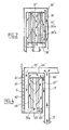
- FIG. 1 we see the closing slab 1 of the tank of a nuclear reactor containing liquid sodium up to level 2.
- the integrated purification device generally designated by the reference 3 plunges inside the sodium liquid and crosses the very thick slab 1 inside a bushing 4.
- the bushing 4 carries at its upper part a flange 6 on which rests a flange 7 integral with the upper part of the suspension shell 8 of the integrated purification device 3.
- a counter-flange 10 makes it possible to fix the purification device after it has been placed in the reactor vessel.
- This ferrule 12 is closed at its lower part by a bottom 13 and thus constitutes a tank filled with lead shot 14 stopping the radiation coming from inside the tank and thus constituting a biological protection.
- This biological protection is completed on the outside of the shell 12 by a solid steel ring 15.
- the shell 12 of the plug also carries at its upper part an annular box 16 filled with heat-insulating material.
- the ferrule 12 of the plug finally carries, via a ferrule 17, all of the wire means tration 18.
- the suspension ferrule 8 comprises an upper part 8a constituted by a simple cylinder of great thickness and a lower part 8b constituted by the assembly of two coaxial cylindrical sheets leaving between them an annular space filled with a liquid metal - heat exchange such as the sodium-potassium eutectic mixture.
- the suspension ferrule 8 ends at its lower part with a ferrule 8c for supporting the economizer exchanger 20 of the purification device.
- the economizer exchanger comprises a tubular bundle formed of vertical tubes connected at their lower part to an annular inlet manifold 21 and at their upper part to a tubular plate also annular 22.
- the cross section of the economizer exchanger is therefore annular on all its height.
- This economizer exchanger 20 comprises two rows of coaxial tubes thus offering a large exchange surface for cooling the sodium of the tank to be purified entering the inlet manifold 21 and circulating in the tubes of the bundle from bottom to top.
- the inner row of tubes of the bundle is closed internally by a ferrule 24 fixed at its upper part on the inner edge of the tubular plate 22.
- the ferrule 24 is closed at its lower part by a curved bottom 25.
- On the inner edge of the tubular plate 22 is also fixed a frustoconical ferrule 26 connected to the casing 27 of the pump 28 and ensuring its suspension in the interior space of the economizer exchanger 20.
- a third envelope 30 made up of cylindrical and spherical frustoconical portions is disposed between the frustoconical support ferrule 26 and the closed ferrule 24-25. This ferrule 30 is connected on its periphery to the ferrule 24 which has openings for the passage of sodium towards the tubes of the bundle between the frustoconical ferrule 26 and the frustoconical part of the envelope 30.
- the pump 28 includes a delivery duct 31 opening into the space between the ferrule 26 and the casing 30.
- the driving part of the pump is arranged around the duct 31, inside the casing 27. Finally, a flow meter 32 is placed at the top of the duct 31 for measuring the sodium flow rate passing through the pump. .
- the upper part of the pump into which the liquid sodium is sucked is in communication with the outlet 18a of the filter 18, the pump and the part 18a of the filter being placed in the extension of one another without being fixed.
- the driving part of the pump is supplied by insulated electrical conductors 34 which are resistant to liquid sodium at high temperature.
- the filter 18 comprises a cylindrical outer casing 35 fixed in an articulated manner to the lower part of the ferrule 17 inside which a second casing 36 is fixed by means of a circular plate 37 comprising openings for the passage of the sodium.
- the envelope 36 is closed at its lower part by a circular plate 38 also pierced with openings for the passage of sodium.
- the envelope 36 contains two tubular filter cartridges 39a and 39b of knitted stainless steel wire arranged coaxially.
- the outlet part 18a of the filter 18 communicates with the interior of the filter cartridge surrounded by the casing 36, by means of the plate per drilled 38.
- the filter 18 is surrounded by the part 8b of the suspension shell 8 inside which is placed a heat exchange liquid such as the eutectic mixture Na-K.
- a heat exchange liquid such as the eutectic mixture Na-K.
- Part 8b of the ferrule 8 has on its external surface, over most of its height disposed opposite the filter 18, fins 40 making it possible to facilitate the heat exchanges between the cooling air circulating in contact with these fins and the liquid contained in part 8b of the ferrule constituting a thermal seal between the internal face and the external face of this suspension ferrule.
- the suspension ferrule carries at the lower end of its part 8b a fixing ring 41 on which is welded a ferrule 42 fixed at its upper part to the flange 7 by means of an expansion bellows 43.
- a ferrule 44 coaxial with the ferrule42 which is itself coaxial with the suspension ferrule 8 is placed between these two ferrules and fixed to the flange 7 by means of an expansion bellows 45.
- the outer shell 42 is covered on its outer surface by a layer of heat-insulating 50 which isolates it from the liquid sodium in which the purification device is immersed.
- the finned outer surface of the ferrule 8 and the ferrules 42 and 44 allowing air circulation of cooling in contact with the fins 40 with return of the air heated by the external annular part constitute the means for additional cooling of the sodium at the level of the filter, this cooling occurring by thermal contact of this sodium with the cooled inner wall of the suspension ferrule 8, via the sodium layer filling the annular space between ferrules 8 and 35.
- the suspension ferrule 8 which is in contact over its entire length with the cooling air entering via the pipe 47 is thus perfectly cooled by this circulating cooling thermal fluid.
- the pump 28 operating in the direction indicated, that is to say creating a suction in the filter 18 through its outlet part 18a, causes a suction sodium in the space between the walls of the filter 35 and 36 via the perforated plate 37.
- the hot sodium to be purified contained in the tank enters the collector 21 then is distributed in the tubes of the economizer exchanger 20 iFessort by the plate tubular 22 to enter the space between the ferrules 35 and 36 through its lower part. It is in this space that the additional cooling of the liquid sodium takes place by the circulation of air in contact with the fins of the suspension shell 8.
- the cooled liquid sodium enters the envelope 36 of this filter containing the filter cartridges 39, through the plate per drilled 37.
- the perforations of the plate 37 are such that the cooled sodium enters the zone of the filter occupied by the filter cartridges 39, both by the central part and by the periphery of these cartridges 39a and 39b.
- the perforations in the lower plate 38 of the filter are such that the sodium emerges in the lower part 18a of the filter through the annular zone between the two filter cartridges 39a and 39b. Purification therefore occurs by crossing the filter cartridges with sodium, both inside and out.
- the cooled and purified sodium collected in the chamber 18a is sucked up by the pump 28, its flow being controlled by the flow meter 32. This flow can be adjusted as a function of the purity of the sodium, by means of adjustment of the supply current. of the pump associated with this pump.
- the cooled and purified liquid sodium is then discharged by the pump into the space between the casings 27 and 30 which is in communication with the upper part of the economizer exchanger 20, outside the bundle tubes.
- the cooled and purified sodium therefore circulates from top to bottom in the bundle, between the ferrule 24 and the bundle closing ferrule arranged in the extension of the ferrule 8c. There is therefore a heat exchange between the cold sodium to be purified circulating outside the tubes and the hot sodium to be purified which enters the bundle through the collector 21.
- the cooled and purified sodium is returned to the tank at the base of the purification device, thanks to a frustoconical ferrule 56 channeling the outgoing flow of liquid sodium.
- the whole of the lower part of the purification device 3 is surrounded by a layer of heat-insulating material 50 fixed on the outer ring 42 making it possible to channel the circulation of cooling air.
- the suspension shell 8 of the purification device is cooled by the circulation of air in contact with its external wall, this air being sent at a temperature of 35 ° by the pipe 47, then recovered by the pipe 48 at a temperature close to 75 °.
- a heat exchanger allowing the cooling of the circulating air placed outside the tank is inserted on a circuit comprising the pipes 47 and 48.
- the pump 28 is surrounded by a space limited by the casing 30 in which circulates the cooled sodium leaving the filter.
- the pump is thus isolated from the hot sodium filling the reactor vessel and protected against thermal stresses appearing during temperature variations in the reactor vessel.
- FIG. 2 an alternative embodiment of the internal part of the filter is seen, making it possible to obtain a circulation of liquid sodium from the upper part of the filter along a path different from that shown in FIG. 1.
- the outer envelope of the filter 35 ′ and the inner envelope 36 ′ containing the cartridges 39 ′ a and 39 ′ b provide between them a space for circulation of the sodium to be purified leaving the economizing exchanger (arrows 55 ′).
- the upper 37 'and lower 38' plates of the inner envelope 36 ' are drilled so that the sodium to be purified enters the filter through the annular space between the cartridges 39'a and 39'b and leaves the filter through the 'central interior space and the peripheral space around the filter, inside the envelope 36'.
- a ferrule 59 separates the two coaxial filter cartridges.
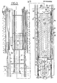
- FIG. 3 we see a second embodiment of a purification device according to the invention; identical references are used for the corresponding elements of the devices shown in the figures res 1 and 3.
- the circulation of sodium inside the purification device is completely reversed compared to the embodiment of FIG. 1.
- the pump 28 sucks sodium between the walls 27 and 30, to discharge it into the inlet space 18a of the filter.
- the sodium surrounding the pump and drawn in by it is cooled sodium having passed through the economizer exchanger from bottom to top.
- the suspension ferrule 8 of the purification device constitutes in this embodiment the external wall of the annular cooling space surrounding the filter 18.
- This cooling space is limited inwards by a coaxial ferrule 60 to the ferrule 8 fixed to the annular part 41 secured to the lower part of the ferrule 8.
- the annular cooling space between the ferrules 8 and 60 is filled with stagnant sodium in which a coil 61 plunges in which an inert gas circulates cooled outside the tank, making it possible to maintain the stagnant sodium between the ferrules 8 and 60 at a relatively low temperature.
- the closure plug of the slab located above the purification device had to be modified as shown to allow the passage of the supply pipes of the cooling coil 61.
- the filter 18 comprises an outer casing 62, an inner casing 63, an upper closing plate 64 and a lower closing plate 65.
- a ferrule 66 fixed on the upper plate 64 makes it possible to separate the filter cartridges 39a and 39b up to a level located above the plate 65.
- the filter also comprises an upper chamber for the outlet of the purified sodium 67 limited externally by a pierced ferrule 68. It is through this chamber 67 that the filter 18 is suspended from the inside the purification device.
- Plate 64 is pierced at its central part trale and the plate 65 at its periphery so that the sodium to be purified coming from the inlet chamber 18a of the pump enters the space between the ferrules 60 and 62 before being channeled to the upper part of the ferrule 63 and come into contact with the filter cartridge 39a.
- the sodium then descends along the shell 66 to come into contact with the internal filter cartridge 39b and go back up into the outlet chamber 67 of the filter through the interior space of the cartridge 39b.
- the purified sodium then passes into the annular space between the ferrules 60 and 62 in which it is cooled by the complementary cooling means 61, via the sodium stagnating in the annular space surrounding the exchange ferrule 60.
- the cooled and purified sodium then arrives in the space limited by the ferrules 8c and 26 above the plate 22 of the tube bundle to enter the tubes of this bundle and to cool the sodium to be purified circulating against the current. outside of the tubes.
- the purified and cooled sodium leaves the purification device via the lower collector 21.
- the supply cables 34 of the pump pass through the annular space directly in contact with the cooling space at the level of the filter 18.
- the filter 18 includes an outer casing 60 'an inner casing 63', an upper bottom 64 'and a lower bottom 65'.
- two ferrules 66 ′ and 67 ′ are also arranged, fixed respectively to the upper plate 64 ′ and to the lower plate 65 ′.
- the exterior envelope 60 ' is closed by two plates 69 'and 70'.
- the ferrule 66 ' is placed in the extension of the outlet pipe 31 of the pump so that the liquid sodium follows the path represented by the arrows 71, first from bottom to top in the ferrule 66', then from top to bottom. low in the annular space between the envelopes 60 'and 63' to arrive under the lower plate 65 ', below openings communicating with the annular space between the two filter cartridges 39a and 39b.
- the sodium to be purified crosses the filter cartridges, the annular space between these cartridges being closed at its upper part.
- the purified sodium is found in the upper part of the filter and flows from top to bottom in the annular space between the ferrules 66 'and 67' to end up in the space limited by the frustoconical ferrule 26 above the tube plate 22.
- the liquid sodium purified and cooled by the devices 61 'arranged between the ferrules 8 and 60' then passes through the tubes of the economizer exchanger where it cools the hot sodium to be purified entering the purification device.
- FIGS. 5, 5a and 5b an alternative embodiment of a cooling device can be seen which can be associated with a purification device as shown in FIG. 1 or as shown in FIG. 3.
- annular space for additional cooling is limited by the suspension ferrule 8 and an internal ferrule 72, the ferrules 8 and 72 being connected at their upper part and at their lower part by annular parts 74 and 75 respectively.
- annular cooling between the ferrules 8 and 72 is introduced a vaporizable cooling fluid 76.
- the annular part 74 has openings in which the finned tubes 77 are tightly fixed. The upper end tubes 77 is closed.
- cooling air is supplied by a device 80 comprising two collectors toric 81 and 82 for the introduction and recovery of air in the annular space by concentric tubes 83 and 84 respectively.
- FIG. 5a we can see the circumferential arrangement of the finned tubes 77 and the cooling air introduction tubes 83. These tubes are arranged one after the other alternately.
- the annular space between the ferrules 8 and 72 and between the annular parts 74 and 75 contains a heat exchange fluid in place of the vaporizable fluid 76, this fluid can be sodium or an organic fluid with a high vaporization point.
- a ferrule 87 disposed between the ferrules 8 and 79 in the upper part of the device allows air circulation in contact with the finned part 86 of the tubes 85.
- the sodium circulating either from bottom to top or from top to bottom in the filter area is cooled by heating the heat exchange fluid placed between the ferrules 8 and 72.
- the heating of this fluid produces the vaporization of the vaporizable fluid contained in the tubes 85; the vapor of this vaporizable fluid rises in the cooling part of the tubes to be condensed there and returned to the lower part of the tube 85.
- FIG. 7 a second variant of the additional cooling device shown in FIG. 5 is seen.
- the device is identical in its upper part to the device shown in FIG. 6 but the lower part of the tubes 95, below the annular part 74 plunges directly into the liquid sodium circulating at the periphery of the filter 18.
- the tubes 95 therefore have a double wall in the lower part and the internal space of this double wall 88 is filled with an exchange liquid such as mercury.
- the main advantages of the device according to the invention are to allow good cooling and therefore maintenance at a moderate temperature of the suspension shell of the purification device and to include a pump placed so as to be surrounded by cooled liquid metal into which leads his ace duct piracy or repression.
- the pump regulates the sodium flow to be purified directly from its control current.
- the ferrules and deflection plates can be arranged so as to channel the sodium in different ways.
- the circulation in the filter cartridges can be done with crossing thereof in parallel or in series.
- the integrated purification device applies to all fast neutron nuclear reactors cooled by liquid metal comprising a tank in which the reactor core is immersed in a liquid metal.
Landscapes
- Physics & Mathematics (AREA)
- Engineering & Computer Science (AREA)
- Plasma & Fusion (AREA)
- General Engineering & Computer Science (AREA)
- High Energy & Nuclear Physics (AREA)
- Chemical & Material Sciences (AREA)
- Chemical Kinetics & Catalysis (AREA)
- Manufacture And Refinement Of Metals (AREA)
- Filtration Of Liquid (AREA)
- Structures Of Non-Positive Displacement Pumps (AREA)
- Heat-Exchange Devices With Radiators And Conduit Assemblies (AREA)
Applications Claiming Priority (2)
| Application Number | Priority Date | Filing Date | Title |
|---|---|---|---|
| FR8417551 | 1984-11-16 | ||
| FR8417551A FR2573563B1 (fr) | 1984-11-16 | 1984-11-16 | Dispositif de purification integre du metal liquide de refroidissement d'un reacteur nucleaire a neutrons rapides |
Publications (2)
| Publication Number | Publication Date |
|---|---|
| EP0184488A1 true EP0184488A1 (de) | 1986-06-11 |
| EP0184488B1 EP0184488B1 (de) | 1988-11-17 |
Family
ID=9309689
Family Applications (1)
| Application Number | Title | Priority Date | Filing Date |
|---|---|---|---|
| EP85402196A Expired EP0184488B1 (de) | 1984-11-16 | 1985-11-13 | Integrierte Reinigungsvorrichtung für Flüssigmetallkühlmittel eines schnellen Neutronenreaktors |
Country Status (4)
| Country | Link |
|---|---|
| EP (1) | EP0184488B1 (de) |
| JP (1) | JPH0631798B2 (de) |
| DE (1) | DE3566318D1 (de) |
| FR (1) | FR2573563B1 (de) |
Cited By (1)
| Publication number | Priority date | Publication date | Assignee | Title |
|---|---|---|---|---|
| FR2603497A1 (fr) * | 1986-09-10 | 1988-03-11 | Commissariat Energie Atomique | Piege froid de purification des metaux liquides contenant des impuretes dissoutes |
Families Citing this family (2)
| Publication number | Priority date | Publication date | Assignee | Title |
|---|---|---|---|---|
| KR101374751B1 (ko) * | 2012-07-17 | 2014-03-17 | 한국수력원자력 주식회사 | 유기유체를 이용한 잔열제거시스템과 잔열제거시스템의 구동방법 |
| CN112951460B (zh) * | 2021-01-29 | 2023-08-18 | 中国科学院近代物理研究所 | 一种用于液态铅基冷却剂过滤净化的冷阱装置 |
Citations (3)
| Publication number | Priority date | Publication date | Assignee | Title |
|---|---|---|---|---|
| FR2246942A1 (de) * | 1973-10-03 | 1975-05-02 | Commissariat Energie Atomique | |
| US4291865A (en) * | 1980-04-22 | 1981-09-29 | Westinghouse Electric Corp. | Radial cold trap |
| FR2521762A1 (fr) * | 1982-02-12 | 1983-08-19 | Doryokuro Kakunenryo | Piege froid installe dans le caisson d'un reacteur surregenerateur rapide du type a coeur ferme, refroidi par metal liquide |
Family Cites Families (1)
| Publication number | Priority date | Publication date | Assignee | Title |
|---|---|---|---|---|
| JPS5990091A (ja) * | 1982-11-16 | 1984-05-24 | 株式会社東芝 | 液体金属用浄化装置 |
-
1984
- 1984-11-16 FR FR8417551A patent/FR2573563B1/fr not_active Expired
-
1985
- 1985-11-13 EP EP85402196A patent/EP0184488B1/de not_active Expired
- 1985-11-13 DE DE8585402196T patent/DE3566318D1/de not_active Expired
- 1985-11-15 JP JP60256484A patent/JPH0631798B2/ja not_active Expired - Lifetime
Patent Citations (3)
| Publication number | Priority date | Publication date | Assignee | Title |
|---|---|---|---|---|
| FR2246942A1 (de) * | 1973-10-03 | 1975-05-02 | Commissariat Energie Atomique | |
| US4291865A (en) * | 1980-04-22 | 1981-09-29 | Westinghouse Electric Corp. | Radial cold trap |
| FR2521762A1 (fr) * | 1982-02-12 | 1983-08-19 | Doryokuro Kakunenryo | Piege froid installe dans le caisson d'un reacteur surregenerateur rapide du type a coeur ferme, refroidi par metal liquide |
Non-Patent Citations (1)
| Title |
|---|
| KERNENERGIE, vol. 22, no. 1, janvier 1979, pages 16-24, Dimitroffgrad, SU; V.I. SUBBOTIN et al.: "Reinigung des Natriumwärmeträgers mittels Kalt- und Heissfallen und Reinigung des Schutzgases" * |
Cited By (3)
| Publication number | Priority date | Publication date | Assignee | Title |
|---|---|---|---|---|
| FR2603497A1 (fr) * | 1986-09-10 | 1988-03-11 | Commissariat Energie Atomique | Piege froid de purification des metaux liquides contenant des impuretes dissoutes |
| EP0260193A1 (de) * | 1986-09-10 | 1988-03-16 | Commissariat A L'energie Atomique | Kaltfallenreinigung von flüssigen Metallen, die Verunreinigungen enthalten |
| US4892653A (en) * | 1986-09-10 | 1990-01-09 | Commissariat A L'energie Atomique | Cold trap for the purification of liquid metals containing dissolved impurities |
Also Published As
| Publication number | Publication date |
|---|---|
| DE3566318D1 (en) | 1988-12-22 |
| JPS61120997A (ja) | 1986-06-09 |
| FR2573563B1 (fr) | 1987-02-06 |
| FR2573563A1 (fr) | 1986-05-23 |
| EP0184488B1 (de) | 1988-11-17 |
| JPH0631798B2 (ja) | 1994-04-27 |
Similar Documents
| Publication | Publication Date | Title |
|---|---|---|
| JPS6193942A (ja) | ヒ−トパイプによつて安定化された試料容器 | |
| FR2462002A1 (fr) | Reacteur nucleaire refroidi par un metal liquide et muni d'un systeme d'evacuation de la puissance residuelle | |
| EP0109877B1 (de) | Reinigungseinrichtung für das aus flüssigem Metall bestehende Kühlmittel eines Kernreaktors mit schnellen Neutronen | |
| EP0184488B1 (de) | Integrierte Reinigungsvorrichtung für Flüssigmetallkühlmittel eines schnellen Neutronenreaktors | |
| EP0068913A1 (de) | Schneller Brüter mit Einrichtung zur Abführung von Restwärme | |
| EP0260193A1 (de) | Kaltfallenreinigung von flüssigen Metallen, die Verunreinigungen enthalten | |
| EP0163564B1 (de) | Schneller Neutronenkernreaktor mit Dampferzeuger, integriert im Behälter | |
| EP0055643A1 (de) | Kernreaktor, der von einem flüssigen Metall gekühlt wird, das in einem oben angeordnete Verschlüsse aufweisenden Behälter enthalten ist | |
| EP0064921B1 (de) | Kühlvorrichtung des Hauptbehälters eines Kernreaktors mit schnellen Neutronen | |
| EP0064920B1 (de) | Vorrichtung zur Dampferzeugung und zur Ableitung von Wärme in einem schnellen Brüter | |
| EP0018262A1 (de) | Schneller Kernreaktor mit einem zylindrischen Innenbehälter | |
| EP0108690B1 (de) | Wärmetauscher für Fluide hoher Temperatur, wobei eines der Fluide an der Oberseite des Wärmetauschers ein- und austritt | |
| EP0006800A1 (de) | Mit flüssigem Metall gekühlter schneller Kernreaktor | |
| EP0095428B1 (de) | Gaskühleinrichtung für den Druckbehälterdeckel eines Kernreaktors | |
| FR2541496A1 (fr) | Reacteur nucleaire a neutrons rapides a structure interne allegee | |
| EP0020264A1 (de) | Wärmetauscher des Teil-Modul-Typs für Kernreaktor | |
| FR2555794A1 (fr) | Reacteur nucleaire a neutrons rapides equipe de moyens de refroidissement de secours | |
| EP0082063A1 (de) | Einrichtung zur Reinigung des flüssigen Metalls zur Kühlung des Kerns eines schnellen Brüters | |
| FR2542911A1 (fr) | Dispositif de purification integree du metal liquide de refroidissement d'un reacteur nucleaire a neutrons rapides | |
| EP0090743B1 (de) | Schutzvorrichtung gegen Wärme und Radiation für einen in einem Kernreaktorbehälter eingetauchten Wärmeübertrager | |
| EP0144256B1 (de) | Anordnung zur thermischen Abschirmung einer Komponente eines Kernreaktors mit schnellen Neutronen | |
| EP0216667B1 (de) | Rückhaltevorrichtung für eine Flüssigkeit um zu verhindern, dass eine offene, im wesentlichen horizontale Leitung beim Unterschreiten einer bestimmten Zuflussmenge leer läuft | |
| FR2542909A1 (fr) | Reacteur nucleaire a neutrons rapides de type integre | |
| FR2561029A1 (fr) | Reacteur nucleaire refroidi par un metal liquide | |
| EP0382643A1 (de) | Wärmeschutzvorrichtung eines oberen Tragringes eines hängenden Gefässes, insbesondere in einem schnellen Neutronenkernreaktor |
Legal Events
| Date | Code | Title | Description |
|---|---|---|---|
| PUAI | Public reference made under article 153(3) epc to a published international application that has entered the european phase |
Free format text: ORIGINAL CODE: 0009012 |
|
| AK | Designated contracting states |
Kind code of ref document: A1 Designated state(s): BE DE GB IT LU NL |
|
| 17P | Request for examination filed |
Effective date: 19860517 |
|
| 17Q | First examination report despatched |
Effective date: 19871208 |
|
| GRAA | (expected) grant |
Free format text: ORIGINAL CODE: 0009210 |
|
| AK | Designated contracting states |
Kind code of ref document: B1 Designated state(s): BE DE GB IT LU NL |
|
| ITF | It: translation for a ep patent filed | ||
| GBT | Gb: translation of ep patent filed (gb section 77(6)(a)/1977) | ||
| REF | Corresponds to: |
Ref document number: 3566318 Country of ref document: DE Date of ref document: 19881222 |
|
| PLBE | No opposition filed within time limit |
Free format text: ORIGINAL CODE: 0009261 |
|
| STAA | Information on the status of an ep patent application or granted ep patent |
Free format text: STATUS: NO OPPOSITION FILED WITHIN TIME LIMIT |
|
| 26N | No opposition filed | ||
| PG25 | Lapsed in a contracting state [announced via postgrant information from national office to epo] |
Ref country code: LU Free format text: LAPSE BECAUSE OF NON-PAYMENT OF DUE FEES Effective date: 19891130 |
|
| PGFP | Annual fee paid to national office [announced via postgrant information from national office to epo] |
Ref country code: LU Payment date: 19901105 Year of fee payment: 6 |
|
| ITPR | It: changes in ownership of a european patent |
Owner name: FUSIONI;FRAMATOME |
|
| EPTA | Lu: last paid annual fee | ||
| NLS | Nl: assignments of ep-patents |
Owner name: FRAMATOME TE COURBEVOIE, FRANKRIJK. |
|
| PGFP | Annual fee paid to national office [announced via postgrant information from national office to epo] |
Ref country code: DE Payment date: 19911111 Year of fee payment: 7 |
|
| PGFP | Annual fee paid to national office [announced via postgrant information from national office to epo] |
Ref country code: BE Payment date: 19911127 Year of fee payment: 7 |
|
| ITTA | It: last paid annual fee | ||
| PGFP | Annual fee paid to national office [announced via postgrant information from national office to epo] |
Ref country code: NL Payment date: 19911130 Year of fee payment: 7 |
|
| REG | Reference to a national code |
Ref country code: GB Ref legal event code: 732 |
|
| PGFP | Annual fee paid to national office [announced via postgrant information from national office to epo] |
Ref country code: GB Payment date: 19921106 Year of fee payment: 8 |
|
| PG25 | Lapsed in a contracting state [announced via postgrant information from national office to epo] |
Ref country code: BE Effective date: 19921130 |
|
| BERE | Be: lapsed |
Owner name: FRAMATOME Effective date: 19921130 |
|
| PG25 | Lapsed in a contracting state [announced via postgrant information from national office to epo] |
Ref country code: NL Effective date: 19930601 |
|
| NLV4 | Nl: lapsed or anulled due to non-payment of the annual fee | ||
| PG25 | Lapsed in a contracting state [announced via postgrant information from national office to epo] |
Ref country code: DE Effective date: 19930803 |
|
| PG25 | Lapsed in a contracting state [announced via postgrant information from national office to epo] |
Ref country code: GB Effective date: 19931113 |
|
| GBPC | Gb: european patent ceased through non-payment of renewal fee |
Effective date: 19931113 |