EP0184517A1 - Verfahren und Anlagen für das katalytische Kracken von Kohlenwasserstoffeinsätzen - Google Patents
Verfahren und Anlagen für das katalytische Kracken von Kohlenwasserstoffeinsätzen Download PDFInfo
- Publication number
- EP0184517A1 EP0184517A1 EP85402416A EP85402416A EP0184517A1 EP 0184517 A1 EP0184517 A1 EP 0184517A1 EP 85402416 A EP85402416 A EP 85402416A EP 85402416 A EP85402416 A EP 85402416A EP 0184517 A1 EP0184517 A1 EP 0184517A1
- Authority
- EP
- European Patent Office
- Prior art keywords
- catalyst
- gas
- regeneration
- stripping
- injected
- Prior art date
- Legal status (The legal status is an assumption and is not a legal conclusion. Google has not performed a legal analysis and makes no representation as to the accuracy of the status listed.)
- Granted
Links
- 238000000034 method Methods 0.000 title claims abstract description 24
- 230000008569 process Effects 0.000 title claims abstract description 19
- 229930195733 hydrocarbon Natural products 0.000 title claims abstract description 15
- 150000002430 hydrocarbons Chemical class 0.000 title claims abstract description 15
- 239000004215 Carbon black (E152) Substances 0.000 title claims abstract description 9
- 238000004523 catalytic cracking Methods 0.000 title claims description 10
- 239000003054 catalyst Substances 0.000 claims abstract description 134
- 230000008929 regeneration Effects 0.000 claims abstract description 58
- 238000011069 regeneration method Methods 0.000 claims abstract description 58
- 239000002245 particle Substances 0.000 claims abstract description 40
- 238000003795 desorption Methods 0.000 claims abstract description 33
- 239000000571 coke Substances 0.000 claims abstract description 26
- 238000005336 cracking Methods 0.000 claims abstract description 20
- 238000002485 combustion reaction Methods 0.000 claims abstract description 13
- 238000004064 recycling Methods 0.000 claims abstract description 6
- 230000006872 improvement Effects 0.000 claims abstract description 4
- 239000007789 gas Substances 0.000 claims description 56
- 239000000567 combustion gas Substances 0.000 claims description 16
- 239000000203 mixture Substances 0.000 claims description 9
- 239000012530 fluid Substances 0.000 claims description 7
- 238000000926 separation method Methods 0.000 claims description 5
- 238000011144 upstream manufacturing Methods 0.000 claims 4
- 238000004231 fluid catalytic cracking Methods 0.000 abstract description 3
- 230000001172 regenerating effect Effects 0.000 abstract description 2
- 230000001174 ascending effect Effects 0.000 abstract 1
- 239000011369 resultant mixture Substances 0.000 abstract 1
- 238000006243 chemical reaction Methods 0.000 description 16
- 230000008901 benefit Effects 0.000 description 6
- JTJMJGYZQZDUJJ-UHFFFAOYSA-N phencyclidine Chemical class C1CCCCN1C1(C=2C=CC=CC=2)CCCCC1 JTJMJGYZQZDUJJ-UHFFFAOYSA-N 0.000 description 6
- 230000009467 reduction Effects 0.000 description 5
- XLYOFNOQVPJJNP-UHFFFAOYSA-N water Chemical compound O XLYOFNOQVPJJNP-UHFFFAOYSA-N 0.000 description 5
- PXHVJJICTQNCMI-UHFFFAOYSA-N Nickel Chemical compound [Ni] PXHVJJICTQNCMI-UHFFFAOYSA-N 0.000 description 4
- 238000009835 boiling Methods 0.000 description 4
- 238000010586 diagram Methods 0.000 description 3
- 238000002347 injection Methods 0.000 description 3
- 239000007924 injection Substances 0.000 description 3
- 238000009834 vaporization Methods 0.000 description 3
- 230000008016 vaporization Effects 0.000 description 3
- UFHFLCQGNIYNRP-UHFFFAOYSA-N Hydrogen Chemical compound [H][H] UFHFLCQGNIYNRP-UHFFFAOYSA-N 0.000 description 2
- 230000003416 augmentation Effects 0.000 description 2
- 239000012159 carrier gas Substances 0.000 description 2
- 238000010276 construction Methods 0.000 description 2
- 235000021183 entrée Nutrition 0.000 description 2
- 230000005484 gravity Effects 0.000 description 2
- 239000001257 hydrogen Substances 0.000 description 2
- 229910052739 hydrogen Inorganic materials 0.000 description 2
- 239000007788 liquid Substances 0.000 description 2
- 229910052759 nickel Inorganic materials 0.000 description 2
- GPPXJZIENCGNKB-UHFFFAOYSA-N vanadium Chemical compound [V]#[V] GPPXJZIENCGNKB-UHFFFAOYSA-N 0.000 description 2
- 229910052720 vanadium Inorganic materials 0.000 description 2
- 230000004913 activation Effects 0.000 description 1
- 230000000712 assembly Effects 0.000 description 1
- 238000000429 assembly Methods 0.000 description 1
- QVGXLLKOCUKJST-UHFFFAOYSA-N atomic oxygen Chemical compound [O] QVGXLLKOCUKJST-UHFFFAOYSA-N 0.000 description 1
- 230000003197 catalytic effect Effects 0.000 description 1
- 150000001875 compounds Chemical class 0.000 description 1
- 239000000470 constituent Substances 0.000 description 1
- 238000007796 conventional method Methods 0.000 description 1
- 230000008021 deposition Effects 0.000 description 1
- 239000000428 dust Substances 0.000 description 1
- ZZUFCTLCJUWOSV-UHFFFAOYSA-N furosemide Chemical compound C1=C(Cl)C(S(=O)(=O)N)=CC(C(O)=O)=C1NCC1=CC=CO1 ZZUFCTLCJUWOSV-UHFFFAOYSA-N 0.000 description 1
- 230000009931 harmful effect Effects 0.000 description 1
- 239000011261 inert gas Substances 0.000 description 1
- 238000004519 manufacturing process Methods 0.000 description 1
- 229910052751 metal Inorganic materials 0.000 description 1
- 239000002184 metal Substances 0.000 description 1
- 150000002739 metals Chemical class 0.000 description 1
- -1 nickel and vanadium Chemical class 0.000 description 1
- TVMXDCGIABBOFY-UHFFFAOYSA-N octane Chemical compound CCCCCCCC TVMXDCGIABBOFY-UHFFFAOYSA-N 0.000 description 1
- 239000001301 oxygen Substances 0.000 description 1
- 229910052760 oxygen Inorganic materials 0.000 description 1
- 239000003208 petroleum Substances 0.000 description 1
- 239000011148 porous material Substances 0.000 description 1
- 230000009257 reactivity Effects 0.000 description 1
- 238000001179 sorption measurement Methods 0.000 description 1
- 239000000725 suspension Substances 0.000 description 1
- 238000004227 thermal cracking Methods 0.000 description 1
Images



Classifications
-
- C—CHEMISTRY; METALLURGY
- C10—PETROLEUM, GAS OR COKE INDUSTRIES; TECHNICAL GASES CONTAINING CARBON MONOXIDE; FUELS; LUBRICANTS; PEAT
- C10G—CRACKING HYDROCARBON OILS; PRODUCTION OF LIQUID HYDROCARBON MIXTURES, e.g. BY DESTRUCTIVE HYDROGENATION, OLIGOMERISATION, POLYMERISATION; RECOVERY OF HYDROCARBON OILS FROM OIL-SHALE, OIL-SAND, OR GASES; REFINING MIXTURES MAINLY CONSISTING OF HYDROCARBONS; REFORMING OF NAPHTHA; MINERAL WAXES
- C10G11/00—Catalytic cracking, in the absence of hydrogen, of hydrocarbon oils
- C10G11/14—Catalytic cracking, in the absence of hydrogen, of hydrocarbon oils with preheated moving solid catalysts
- C10G11/18—Catalytic cracking, in the absence of hydrogen, of hydrocarbon oils with preheated moving solid catalysts according to the "fluidised-bed" technique
Definitions
- the present invention relates to catalytic cracking of hydrocarbon charges. It relates more particularly to improvements made to the regeneration of the spent catalyst of such a process, with a view to the use of "load elevators" shorter than those of the prior art.
- the most commonly used process for this purpose is the so-called fluid catalytic cracking process (in English, Fluid Catalytic Cracking, or FCC process).
- FCC process Fluid Catalytic Cracking
- the hydrocarbon charge is simultaneously vaporized and brought into contact at high temperature with a cracking catalyst, which is kept in suspension in the vapors of the charge. After the desired molecular weight range has been reached by cracking, with a corresponding lowering of the boiling points, the catalyst is separated from the products obtained.
- the catalyst of the FCC process and the charge to be treated are injected under pressure and at an elevated temperature at the base of a column called "charge elevator", which technicians often designate by the English term “riser” .
- charge elevator At the top of the column is generally arranged a tank concentric with the elevator.
- a ballistic separation system such as a cyclone, in which the spent catalyst is separated from the cracked charge.
- This is evacuated at the top of said tank, after passing through cyclones, to reduce the entrainment of dust, while the recovered catalyst particles encounter a stripping gas such as water vapor, injected for example annularly at the base of said tank, before being evacuated to a regenerator.
- Combustion air is injected, for example annularly, at the base of the regenerator, while at the top of the latter are provided cyclones making it possible to separate the combustion gas from the particles of regenerated catalyst.
- This is evacuated to the bottom of the regenerator and recycled to the base of the elevator or "riser", where the charge is usually injected at a temperature between 80 ° C and 400 ° C and under a pressure ranging from 0 , 7.10 5 to 3.5.105 relative Pascals.
- the quantity of coke present on the catalyst, at the entry of the regeneration zone, as well as the regeneration mode will determine the final temperature reached in the regeneration zone, because the calories coming from the combustion of the coke serve at the same time, in addition to the heat losses, to reheat the regeneration fluid (air and / or oxygen) and are shared between the combustion gases and the catalyst particles. Under operating conditions, the quantity of coke produced in the cracking unit will therefore be substantially constant, if the thermal equilibrium is not modified by external constraints.
- n denotes the efficiency of the exchange of combustion heat with the catalyst
- ⁇ H the heat of combustion of coke
- C the specific heat of the catalyst
- the Applicant has established that effective desorption of the products entrained by the spent catalyst grains, prior to their regeneration, contributes to obtaining these results.
- the stripping of the used catalyst aims to displace by a gas, usually steam, the hydrocarbons entrained in the voids separating the catalyst grains and, to a certain extent, the lighter hydrocarbons adsorbed on the surface in the pores of the catalyst. It is known, in fact, that a badly stripped catalyst before its regeneration has a higher ⁇ coke and a hydrogen concentration on the deposited coke greater than 7% by weight.
- the present invention provides for carrying out, after the conventional stripping of the catalyst, a desorption of the products entrained by the spent catalyst at a temperature at least 25 ° C higher than that of the particles of catalyst having just undergone a stripping.
- This desorption will advantageously be carried out by injection of combustion gases coming from the regenerator (s) in the current of the catalyst flow. This injection also makes it possible to bring this catalyst to the height required for feeding the regenerator or regenerators, which makes it possible to use a shorter load lifter than in the prior art.
- the subject of the present invention is therefore, in a process for the catalytic cracking in the fluid state of a hydrocarbon charge, comprising a phase of contacting in an upward flow in an elevator, under cracking conditions, of said said charge and particles of a cracked catalyst, a phase of separation of the spent catalyst and the cracked charge, downstream of the upper end of said riser, a phase of stripping of the spent catalyst using an injected gas against the flow of this catalyst, a phase of regeneration of said catalyst under conditions of combustion of the coke deposited thereon, and a phase of recycling of the regenerated catalyst to the supply of said elevator, the improvement consisting in that, after having undergone said stripping and before being subjected to said regeneration, said catalyst is subjected to a desorption by a gas injected cocurrently with the catalyst at a temperature at least 25 ° C. higher than the temperature of the catalyst particles just undergone said stripping stage, and the resulting mixture is injected ⁇ in the fluidized portion of the regeneration zone which is located above the dense fluidized bed.
- the gas used for the desorption phase may be an inert gas or water vapor, but, in a preferred embodiment of the invention, use will be made of the gases originating from the regeneration of the catalyst, which have l advantage of being at a higher temperature than the catalyst to be regenerated, either alone or in mixture with steam.
- the invention also relates to a catalytic cracking device in the fluid state of hydrocarbon charges, comprising a riser type column, means arranged at the base of said elevator for supplying the latter under pressure with a hydrocarbon charge and particles of a cracking catalyst, a means of stripping by a gas of spent catalyst particles in an enclosure disposed at the top of said elevator, concentrically thereto, this stripping gas being injected into this enclosure against the current of the spent catalyst particles, at least one unit for regenerating said catalyst by combustion of the coke deposited thereon, and means for recycling the regenerated catalyst to said supply means, said device being characterized in that it comprises, between said stripping means and said regeneration unit, means for desorption by a second gas of the products entrained by the particles of the catalyst, this desorption means being such that the second gas is injected under pressure into the flow of the co-current catalyst particles thereof, and that the resulting mixture of spent catalyst and gas is injected into the fluidized part of the regeneration zone which is located above the dense fluidized bed.
- Said desorption means will advantageously be placed in the device at a level lower than that of said regeneration unit, said gas thus injected co-current then also serving as carrier gas for said particles, which allows the use of an elevator short.
- the desorption gas may or may not be identical to the stripping gas.
- it will be constituted at least in part by the gases coming from the regeneration unit.
- a desorption means provides the catalyst particles with additional driving pressure, which makes it possible to diversify the positioning of the different units of the cracking device, in particular the elevator and the regenerator. It also improves the qualities of the stripping, in particular if the gases coming from the regeneration unit are used as injection gas, which have a higher temperature of about 25 and if possible about 100 ° C. that at which stripping is carried out, which makes it possible to significantly reduce the A coke and to limit the latter to the reaction ⁇ coke, with the consequence of a less release of heat during regeneration and a less degraded and more stable catalyst. We can thus reduce the length of the elevator and / or process heavier loads. Finally, it is possible to better control and regularize the supply of spent catalyst to the regenerator, with the advantage of being able to control its temperature by limiting hot spots, which preserves the stability of the catalyst, and thus to obtain a better regenerated catalyst and therefore more active.
- the length of the elevator must be emphasized. It allows, on the one hand, to obtain a better selectivity in cracked products of the gasoline type and light distillates, on the other hand, to raise the temperature of the elevator without increased production of gas and even with a reduction in Acoke. A better conversion of the charge is therefore obtained, with a better octane number of the resulting products, and heavier charges which are more difficult to crack can be treated. A reduced height lift also lends itself to ultra-short residence times of the load.
- the invention applies equally to cracking assemblies comprising two regeneration units in series as to those comprising a single regeneration unit.
- the device for cracking by the FCC process shown in FIG. 1 is of a type known per se. It essentially comprises a column 1 known as a charge riser, or else a "riser", supplied at its base, by line 2, with the charge to be treated and, via line 3, with particles of a cracking catalyst.
- Column 1 opens at its apex in an enclosure 4 which is concentric with it and in which, on the one hand, the separation of the cracked charge takes place and, on the other hand, the stripping of the spent catalyst.
- the treated charge is separated in a cyclone 5, which is housed in the enclosure 4, at the top of which a discharge line 6 of the cracked charge is provided, while the spent catalyst particles are discharged at the base of the enclosure 4.
- a line 7 supplies stripping gas, generally water vapor, to injectors 8 regularly arranged at the base of enclosure 4. Stripping is therefore preferably carried out in a dense medium against the current of the catalyst.
- the spent catalyst particles thus stripped are evacuated at the base of the enclosure 4 to a regenerator 9, by means of a conduit 10, on which is provided a control valve 11.
- the regenerator 9 the coke deposited on the particles of the catalyst is burned using air, injected at the base of the regenerator by a line 12, which supplies injectors 13 regularly spaced.
- the particles of the treated catalyst entrained by the combustion gas are separated by cyclones 14, from which the combustion gas is evacuated by a line 15, while the particles of catalyst are discharged towards the base of the regenerator 9, from where they are recycled through line 3, fitted with a control valve 16, to the supply of elevator 1.
- FIG. 2 represents a device according to the invention, in which the members already described in relation to FIG. 1 are designated by the same reference numbers assigned to the index '.
- the conduit 10 ' through which the spent catalyst particles are discharged from the enclosure 4' disposed at the upper end of the elevator 1 ', does not open directly into the regenerator 9', but present here a vertical portion 101, communicating through a portion 102 with the regenerator 9 ', and connected by an elbow to the lower end of the conduit 10'.
- the base of the duct 101 is supplied with a desorption gas by a line 18.
- this desorption gas can be constituted by a mixture of steam, brought to the line 18 by the line 19, and of effluent gas from the regenerator 9 ′, derived from line 15 ′ to line 18 by line 20, equipped with the pump 21.
- the desorption of the catalyst particles is carried out co-current in the vertical part 101 , that the resulting mixture of spent catalyst and gas is injected into the fluidized part of the regeneration zone which is located above the dense fluidized bed, thus allowing good separation of the gases and the grains of catalyst, and that the gas of desorption acts as a carrier gas to raise the particles to the regenerator.
- the enclosure 4 ′ will not be at a sufficient height so that the spent catalyst particles can, by simple gravity, feed the regenerator 9 and, after regeneration, be recycled to the supply of the elevator 1 ′ .
- the desorption gas injected at a temperature at least 25 ° C higher than that of the catalyst, enters via the line 18 in the section of conduit 101 and therefore advantageously exerts a suitable desorption and a thrust on the spent catalyst particles to route them to the regenerator.
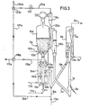
- FIGS 3 and 4 illustrate two other forms of implementation of the catalytic cracking method according to the invention, in which a two-stage regeneration enclosure is used.
- the members already described in relation to Figures 1 and 2 are designated by the same reference numbers, assigned the indices a and b, respectively.
- the regenerator 9a is in an upward flow and comprises two stages 91a and 91b.
- the spent catalyst which has already undergone stripping in the enclosure 4a is conveyed by line 10a, the vertical section of pipe 10la and the horizontal section 102c to the lower stage 91a of the regenerator.
- a desorption gas is injected under pressure through line 18a at the bottom of the vertical section 101a; this desorption gas comprises a mixture of combustion gases coming from the regeneration enclosure, supplied by line 20a, and optionally steam, supplied by line 19a.
- the base of the first combustion stage 91a is supplied with air by the line 12a and the air is distributed by regularly spaced injectors 13a.
- cyclones 14a separate the combustion gas from the partially regenerated catalyst particles.
- the combustion gas is conveyed to line 20a by a line 115, fitted with a valve 116, making it possible to divert part of the gas flow to a line 117.
- the particles of the catalyst having undergone a first regeneration treatment are then transferred to the second stage 91b of the regenerator by the central duct 110a, supplied with air by the line IIIa.
- stage 91b The base of stage 91b is also supplied with air by line 112a and by injectors 113a.
- the particles of the regenerated catalyst are discharged laterally in a buffer enclosure 118a and are recycled through the conduit 3a to the supply of the elevator la.
- the combustion gases evacuated at the top of stage 91b are treated in an external cyclone 119a, at the base of which the particles of the catalyst are returned by the conduit 120a to stage 91a, while the combustion gases are evacuated by lines 121a and 20a to line 18a.
- a safety valve 122a is provided on line 121a and a valve 123a makes it possible to divert part of the gas to a line 124a.
- the embodiment of FIG. 4 also includes a two-stage regenerator 9b 92a and 92b with downward flow.
- the catalyst already stripped in the enclosure 4b is conveyed by the conduit 10b, the vertical section 101b and the horizontal section 102b to the upper stage 92b.
- Desorption gas is injected under pressure into the lower part of the vertical duct 101b via a line 18b.
- This stripping gas can consist of a mixture of steam, supplied by line 19b, and combustion gases, originating of regenerator 9b via line 20b.
- Air is injected at the base of stage 92b through line 112b and injectors 113b.
- Cyclones 14b separate the suspended particles from the combustion gas, which is evacuated by a line 121b, on which a valve 123b makes it possible to divert part of the combustion gas to a line 124b.
- the particles treated in the first stage 92b are conveyed by gravity through the conduit 125 to the lower stage 92a of the regenerator, at the base of which air is injected via the line 112b and the injectors 113b.
- the combustion gas is evacuated to an external cyclone 119b, from where the catalyst particles are returned by the conduit 120b to stage 92a, while the gas is evacuated by line 115b to line 20b.
- a valve 116b makes it possible to divert part of the gas to an auxiliary line 117b.
- the regenerated catalyst is evacuated from the base of stage 92a via line 3b and recycled to the supply of the elevator lb.
Landscapes
- Chemical & Material Sciences (AREA)
- Oil, Petroleum & Natural Gas (AREA)
- Engineering & Computer Science (AREA)
- Chemical Kinetics & Catalysis (AREA)
- General Chemical & Material Sciences (AREA)
- Organic Chemistry (AREA)
- Production Of Liquid Hydrocarbon Mixture For Refining Petroleum (AREA)
- Catalysts (AREA)
Applications Claiming Priority (2)
| Application Number | Priority Date | Filing Date | Title |
|---|---|---|---|
| FR8418706A FR2574422B1 (fr) | 1984-12-07 | 1984-12-07 | Perfectionnements aux procedes et dispositifs pour le craquage catalytique a l'etat fluide de charges d'hydrocarbures |
| FR8418706 | 1984-12-07 |
Publications (2)
| Publication Number | Publication Date |
|---|---|
| EP0184517A1 true EP0184517A1 (de) | 1986-06-11 |
| EP0184517B1 EP0184517B1 (de) | 1988-05-18 |
Family
ID=9310352
Family Applications (1)
| Application Number | Title | Priority Date | Filing Date |
|---|---|---|---|
| EP85402416A Expired EP0184517B1 (de) | 1984-12-07 | 1985-12-04 | Verfahren und Anlagen für das katalytische Kracken von Kohlenwasserstoffeinsätzen |
Country Status (5)
| Country | Link |
|---|---|
| EP (1) | EP0184517B1 (de) |
| CN (1) | CN1006895B (de) |
| DE (1) | DE3562780D1 (de) |
| FR (1) | FR2574422B1 (de) |
| ZA (1) | ZA859374B (de) |
Cited By (10)
| Publication number | Priority date | Publication date | Assignee | Title |
|---|---|---|---|---|
| FR2624877A1 (fr) * | 1987-12-22 | 1989-06-23 | Inst Francais Du Petrole | Procede et dispositif pour le craquage catalytique de charges lourdes comportant un second strippage en lit fluide |
| FR2624762A1 (fr) * | 1987-12-21 | 1989-06-23 | Total France | Procede et dispositif de regeneration de catalyseur en lit fluidise |
| FR2627187A1 (fr) * | 1988-02-15 | 1989-08-18 | Inst Francais Du Petrole | Procede de craquage a l'etat fluide d'une charge d'hydrocarbures |
| EP0433504A1 (de) * | 1988-05-25 | 1991-06-26 | Mobil Oil Corporation | Verfahren für das Strippen von verbrauchtem FCC-Katalysator |
| EP0702077A3 (de) * | 1994-09-13 | 1996-03-27 | Bar Co Processes Joint Venture | |
| US5506365A (en) * | 1987-12-30 | 1996-04-09 | Compagnie De Raffinage Et De Distribution Total France | Process and apparatus for fluidized-bed hydrocarbon conversion |
| US6447671B1 (en) | 1999-03-25 | 2002-09-10 | Institut Francais Du Petrole | Process for converting heavy petroleum fractions, comprising an ebullated bed hydroconversion step and a hydrotreatment step |
| WO2013083883A1 (fr) | 2011-12-07 | 2013-06-13 | IFP Energies Nouvelles | Procede d'hydroconversion de charges petrolieres en lits fixes pour la production de fiouls a basse teneur en soufre |
| WO2014096704A1 (fr) | 2012-12-20 | 2014-06-26 | IFP Energies Nouvelles | Procédé avec separation de traitement de charges petrolieres pour la production de fiouls a basse teneur en soufre |
| WO2014096703A1 (fr) | 2012-12-20 | 2014-06-26 | IFP Energies Nouvelles | Procédé integré de traitement de charges petrolieres pour la production de fiouls a basse teneur en soufre |
Families Citing this family (9)
| Publication number | Priority date | Publication date | Assignee | Title |
|---|---|---|---|---|
| CN1056543C (zh) * | 1996-08-20 | 2000-09-20 | 中国石油化工总公司 | 催化裂化提升管反应器 |
| CN1109091C (zh) * | 1997-12-23 | 2003-05-21 | 中国石油化工集团公司 | 重油流化催化裂化重叠式两段再生技术 |
| CN1078492C (zh) * | 1998-09-25 | 2002-01-30 | 清华大学 | 用于强放热反应过程密相循环流化床反应器 |
| CN1087647C (zh) * | 1998-12-25 | 2002-07-17 | 中国石油化工集团公司 | 液固移动床反应器 |
| RU2194569C1 (ru) * | 2001-10-18 | 2002-12-20 | Общество с ограниченной ответственностью "Лукойл-Пермнефтеоргсинтез" | Реакторно-регенерационный блок установки каталитического крекинга |
| CN102276402B (zh) * | 2010-06-11 | 2013-12-04 | 中国石油化工股份有限公司 | 生产低碳烯烃的组合反应装置 |
| FR2981659B1 (fr) | 2011-10-20 | 2013-11-01 | Ifp Energies Now | Procede de conversion de charges petrolieres comprenant une etape d'hydroconversion en lit bouillonnant et une etape d'hydrotraitement en lit fixe pour la production de fiouls a basse teneur en soufre |
| FR2999600B1 (fr) | 2012-12-18 | 2015-11-13 | IFP Energies Nouvelles | Procede de raffinage d'une charge hydrocarbonee lourde mettant en oeuvre un desasphaltage selectif |
| CN107271352B (zh) * | 2017-06-30 | 2019-12-31 | 上海理工大学 | 一种颗粒温度和颗粒运动同步测量装置和方法 |
Citations (4)
| Publication number | Priority date | Publication date | Assignee | Title |
|---|---|---|---|---|
| BE535572A (de) * | 1954-02-09 | |||
| US2843460A (en) * | 1953-04-07 | 1958-07-15 | Standard Oil Dev Co | Contacting of gases with fluidized solids |
| GB1293168A (en) * | 1969-12-08 | 1972-10-18 | Exxon Research Engineering Co | Two-stage countercurrent catalyst regenerator |
| WO1982004061A1 (en) * | 1981-05-13 | 1982-11-25 | Mckay William E Jr | Stripping hydrocarbons from catalyst with combustion gases |
-
1984
- 1984-12-07 FR FR8418706A patent/FR2574422B1/fr not_active Expired
-
1985
- 1985-12-04 EP EP85402416A patent/EP0184517B1/de not_active Expired
- 1985-12-04 DE DE8585402416T patent/DE3562780D1/de not_active Expired
- 1985-12-06 CN CN85108854A patent/CN1006895B/zh not_active Expired
- 1985-12-06 ZA ZA859374A patent/ZA859374B/xx unknown
Patent Citations (4)
| Publication number | Priority date | Publication date | Assignee | Title |
|---|---|---|---|---|
| US2843460A (en) * | 1953-04-07 | 1958-07-15 | Standard Oil Dev Co | Contacting of gases with fluidized solids |
| BE535572A (de) * | 1954-02-09 | |||
| GB1293168A (en) * | 1969-12-08 | 1972-10-18 | Exxon Research Engineering Co | Two-stage countercurrent catalyst regenerator |
| WO1982004061A1 (en) * | 1981-05-13 | 1982-11-25 | Mckay William E Jr | Stripping hydrocarbons from catalyst with combustion gases |
Cited By (15)
| Publication number | Priority date | Publication date | Assignee | Title |
|---|---|---|---|---|
| FR2624762A1 (fr) * | 1987-12-21 | 1989-06-23 | Total France | Procede et dispositif de regeneration de catalyseur en lit fluidise |
| EP0322274A1 (de) * | 1987-12-21 | 1989-06-28 | Société Anonyme dite: COMPAGNIE DE RAFFINAGE ET DE DISTRIBUTION TOTAL FRANCE | Verfahren und Einrichtung für das Regenerieren von Katalysatoren in einer Wirbelschicht |
| US4959334A (en) * | 1987-12-21 | 1990-09-25 | C. Compagnie de Raffinage et de Distribution | Fluidized-bed catalyst regeneration |
| CN1040729C (zh) * | 1987-12-21 | 1998-11-18 | 法国精制和总分配公司 | 流化床催化剂再生的方法和设备 |
| EP0322276A1 (de) * | 1987-12-22 | 1989-06-28 | Institut Français du Pétrole | Verfahren und Einrichtung für das katalytische Kracken von schweren Einsätze, die eine zweite Wirbelschichtabstreifzone enthalten |
| FR2624877A1 (fr) * | 1987-12-22 | 1989-06-23 | Inst Francais Du Petrole | Procede et dispositif pour le craquage catalytique de charges lourdes comportant un second strippage en lit fluide |
| US5506365A (en) * | 1987-12-30 | 1996-04-09 | Compagnie De Raffinage Et De Distribution Total France | Process and apparatus for fluidized-bed hydrocarbon conversion |
| FR2627187A1 (fr) * | 1988-02-15 | 1989-08-18 | Inst Francais Du Petrole | Procede de craquage a l'etat fluide d'une charge d'hydrocarbures |
| EP0433504A1 (de) * | 1988-05-25 | 1991-06-26 | Mobil Oil Corporation | Verfahren für das Strippen von verbrauchtem FCC-Katalysator |
| US5584986A (en) * | 1993-03-19 | 1996-12-17 | Bar-Co Processes Joint Venture | Fluidized process for improved stripping and/or cooling of particulate spent solids, and reduction of sulfur oxide emissions |
| EP0702077A3 (de) * | 1994-09-13 | 1996-03-27 | Bar Co Processes Joint Venture | |
| US6447671B1 (en) | 1999-03-25 | 2002-09-10 | Institut Francais Du Petrole | Process for converting heavy petroleum fractions, comprising an ebullated bed hydroconversion step and a hydrotreatment step |
| WO2013083883A1 (fr) | 2011-12-07 | 2013-06-13 | IFP Energies Nouvelles | Procede d'hydroconversion de charges petrolieres en lits fixes pour la production de fiouls a basse teneur en soufre |
| WO2014096704A1 (fr) | 2012-12-20 | 2014-06-26 | IFP Energies Nouvelles | Procédé avec separation de traitement de charges petrolieres pour la production de fiouls a basse teneur en soufre |
| WO2014096703A1 (fr) | 2012-12-20 | 2014-06-26 | IFP Energies Nouvelles | Procédé integré de traitement de charges petrolieres pour la production de fiouls a basse teneur en soufre |
Also Published As
| Publication number | Publication date |
|---|---|
| ZA859374B (en) | 1986-09-24 |
| CN1006895B (zh) | 1990-02-21 |
| FR2574422B1 (fr) | 1988-01-08 |
| FR2574422A1 (fr) | 1986-06-13 |
| CN85108854A (zh) | 1986-05-10 |
| DE3562780D1 (en) | 1988-06-23 |
| EP0184517B1 (de) | 1988-05-18 |
Similar Documents
| Publication | Publication Date | Title |
|---|---|---|
| EP0184517B1 (de) | Verfahren und Anlagen für das katalytische Kracken von Kohlenwasserstoffeinsätzen | |
| EP0208609B2 (de) | Verfahren und Einrichtung für das katalytische Kracken von Kohlenwasserstoffen mit Kontrolle der Reaktionstemperatur | |
| EP0322274B1 (de) | Verfahren und Einrichtung für das Regenerieren von Katalysatoren in einer Wirbelschicht | |
| EP0332536B1 (de) | Verfahren und Vorrichtung zum Regenerieren eines Katalysators in einem Fliessbett | |
| EP0191695B1 (de) | Verfahren und Einrichtung für die Injektion von Katalysator in ein katalytisches Wirbelschichtkrackverfahren, insbesondere von schweren Einsätzen | |
| EP0323297B1 (de) | Wirbelschichtverfahren zur Kohlenwasserstoffumwandlung | |
| EP0479645A1 (de) | Fluidisiertes katalytisches Krackverfahren und -apparat mit Abwärtsfliessung | |
| CA1259577A (fr) | Procede et appareil pour craquage catalytique en lit fluide | |
| EP0489726B1 (de) | Verfahren und einrichtung zum dampfkracken von kohlenwasserstoffen in der wirbelschichtphase | |
| EP0485259B1 (de) | Verfahren und Einrichtung für Homogenisierung in ein röhrenformige Kohlenwasserstoff-Krackreaktor mit Wirbelbett von feste Teilchen, von das Gemisch von diese Teilchen und die zu behandeln Kohlenwasserstoffen | |
| FR2659346A1 (fr) | Procede de craquage avec oligomerisation ou trimerisation des olefines presentes dans les effluents. | |
| EP2366760B1 (de) | Verfahren zum katalytischen Cracken mit feiner Kontrolle des Restgehalts an Koks auf dem Katalysator nach Regenerierung | |
| EP0874880B1 (de) | Fluidkatalytisch krackverfahren und -einrichtung fur kohlenwasserstoffeinsätze | |
| EP0663434A1 (de) | Fluidkatalytisch Krachverfahren für Kohlenwasserstoffeinsätze, insbesondere Einsätze mit hoher basischen Stickstoffgehalten | |
| EP0573316B1 (de) | Verfahren und Einrichtung zum katalytischen Kracken in zwei aufeinanderfolgenden Reaktionszonen | |
| CA2250342A1 (fr) | Procede et dispositif de vaporisation selective des charges d'hydrocarbures en craquage catalytique | |
| EP0536054B1 (de) | Verbesserungen an Vorrichtungen für das katalytische Wirbelschichtkracken von Kohlenwasserstoffeinsätzen | |
| EP0322276A1 (de) | Verfahren und Einrichtung für das katalytische Kracken von schweren Einsätze, die eine zweite Wirbelschichtabstreifzone enthalten | |
| EP0265347A1 (de) | Verfahren und Vorrichtung für die katalytische Wirbelschichtspaltung von Kohlenwasserstoffeinsätzen | |
| EP1016444A1 (de) | Verfahren und Vorrichtung für die schnelle Abtrennung von festen Partikeln aus gasförmigen Fluiden und ihre Anwendung | |
| FR2658833A1 (fr) | Procede de craquage a l'etat fluide d'une charge d'hydrocarbures. | |
| FR2659976A1 (fr) | Craquage catalytique avec refroidissement brusque. | |
| FR2621322A1 (fr) | Procede de vaporisation d'une charge liquide dans un procede de craquage catalytique en lit fluide | |
| FR2633848A1 (fr) | Procede et dispositif de regeneration d'un catalyseur use avec echange thermique en lit fluidise | |
| FR2617860A1 (fr) | Procede de craquage a l'etat fluide d'une charge d'hydrocarbures |
Legal Events
| Date | Code | Title | Description |
|---|---|---|---|
| PUAI | Public reference made under article 153(3) epc to a published international application that has entered the european phase |
Free format text: ORIGINAL CODE: 0009012 |
|
| AK | Designated contracting states |
Kind code of ref document: A1 Designated state(s): BE CH DE FR GB IT LI LU NL |
|
| 17P | Request for examination filed |
Effective date: 19860929 |
|
| 17Q | First examination report despatched |
Effective date: 19870827 |
|
| GRAA | (expected) grant |
Free format text: ORIGINAL CODE: 0009210 |
|
| ITF | It: translation for a ep patent filed | ||
| AK | Designated contracting states |
Kind code of ref document: B1 Designated state(s): BE CH DE FR GB IT LI LU NL |
|
| REF | Corresponds to: |
Ref document number: 3562780 Country of ref document: DE Date of ref document: 19880623 |
|
| RAP2 | Party data changed (patent owner data changed or rights of a patent transferred) |
Owner name: COMPAGNIE DE RAFFINAGE ET DE DISTRIBUTION TOTAL F |
|
| REG | Reference to a national code |
Ref country code: CH Ref legal event code: PFA Free format text: COMPAGNIE DE RAFFINAGE ET DE DISTRIBUTION TOTAL FRANCE |
|
| GBT | Gb: translation of ep patent filed (gb section 77(6)(a)/1977) | ||
| BECN | Be: change of holder's name |
Effective date: 19880518 |
|
| PG25 | Lapsed in a contracting state [announced via postgrant information from national office to epo] |
Ref country code: LU Free format text: LAPSE BECAUSE OF NON-PAYMENT OF DUE FEES Effective date: 19881231 |
|
| PLBE | No opposition filed within time limit |
Free format text: ORIGINAL CODE: 0009261 |
|
| STAA | Information on the status of an ep patent application or granted ep patent |
Free format text: STATUS: NO OPPOSITION FILED WITHIN TIME LIMIT |
|
| 26N | No opposition filed | ||
| PGFP | Annual fee paid to national office [announced via postgrant information from national office to epo] |
Ref country code: LU Payment date: 19891115 Year of fee payment: 5 |
|
| PGFP | Annual fee paid to national office [announced via postgrant information from national office to epo] |
Ref country code: BE Payment date: 19891206 Year of fee payment: 5 |
|
| PGFP | Annual fee paid to national office [announced via postgrant information from national office to epo] |
Ref country code: CH Payment date: 19891212 Year of fee payment: 5 |
|
| PGFP | Annual fee paid to national office [announced via postgrant information from national office to epo] |
Ref country code: DE Payment date: 19891222 Year of fee payment: 5 |
|
| ITTA | It: last paid annual fee | ||
| PG25 | Lapsed in a contracting state [announced via postgrant information from national office to epo] |
Ref country code: LI Effective date: 19901231 Ref country code: CH Effective date: 19901231 Ref country code: BE Effective date: 19901231 |
|
| PGFP | Annual fee paid to national office [announced via postgrant information from national office to epo] |
Ref country code: NL Payment date: 19901231 Year of fee payment: 6 |
|
| BERE | Be: lapsed |
Owner name: CIE DE RAFFINAGE ET DE DISTRIBUTION TOTAL FRANCE Effective date: 19901231 |
|
| REG | Reference to a national code |
Ref country code: CH Ref legal event code: PL |
|
| PG25 | Lapsed in a contracting state [announced via postgrant information from national office to epo] |
Ref country code: DE Effective date: 19910903 |
|
| PG25 | Lapsed in a contracting state [announced via postgrant information from national office to epo] |
Ref country code: NL Effective date: 19920701 |
|
| NLV4 | Nl: lapsed or anulled due to non-payment of the annual fee | ||
| PGFP | Annual fee paid to national office [announced via postgrant information from national office to epo] |
Ref country code: GB Payment date: 20011123 Year of fee payment: 17 |
|
| PGFP | Annual fee paid to national office [announced via postgrant information from national office to epo] |
Ref country code: FR Payment date: 20011228 Year of fee payment: 17 |
|
| REG | Reference to a national code |
Ref country code: GB Ref legal event code: IF02 |
|
| PG25 | Lapsed in a contracting state [announced via postgrant information from national office to epo] |
Ref country code: GB Free format text: LAPSE BECAUSE OF NON-PAYMENT OF DUE FEES Effective date: 20021204 |
|
| GBPC | Gb: european patent ceased through non-payment of renewal fee | ||
| PG25 | Lapsed in a contracting state [announced via postgrant information from national office to epo] |
Ref country code: FR Free format text: LAPSE BECAUSE OF NON-PAYMENT OF DUE FEES Effective date: 20030901 |
|
| REG | Reference to a national code |
Ref country code: FR Ref legal event code: ST |