EP0184931A2 - Kabelführungssystem für Fahrzeuge - Google Patents
Kabelführungssystem für Fahrzeuge Download PDFInfo
- Publication number
- EP0184931A2 EP0184931A2 EP19850308896 EP85308896A EP0184931A2 EP 0184931 A2 EP0184931 A2 EP 0184931A2 EP 19850308896 EP19850308896 EP 19850308896 EP 85308896 A EP85308896 A EP 85308896A EP 0184931 A2 EP0184931 A2 EP 0184931A2
- Authority
- EP
- European Patent Office
- Prior art keywords
- channel
- conduit system
- elements
- channels
- channel elements
- Prior art date
- Legal status (The legal status is an assumption and is not a legal conclusion. Google has not performed a legal analysis and makes no representation as to the accuracy of the status listed.)
- Granted
Links
Images


Classifications
-
- H—ELECTRICITY
- H02—GENERATION; CONVERSION OR DISTRIBUTION OF ELECTRIC POWER
- H02G—INSTALLATION OF ELECTRIC CABLES OR LINES, OR OF COMBINED OPTICAL AND ELECTRIC CABLES OR LINES
- H02G3/00—Installations of electric cables or lines or protective tubing therefor in or on buildings, equivalent structures or vehicles
- H02G3/02—Details
- H02G3/04—Protective tubing or conduits, e.g. cable ladders or cable troughs
- H02G3/0406—Details thereof
- H02G3/0418—Covers or lids; Their fastenings
-
- H—ELECTRICITY
- H02—GENERATION; CONVERSION OR DISTRIBUTION OF ELECTRIC POWER
- H02G—INSTALLATION OF ELECTRIC CABLES OR LINES, OR OF COMBINED OPTICAL AND ELECTRIC CABLES OR LINES
- H02G3/00—Installations of electric cables or lines or protective tubing therefor in or on buildings, equivalent structures or vehicles
- H02G3/02—Details
- H02G3/04—Protective tubing or conduits, e.g. cable ladders or cable troughs
- H02G3/0437—Channels
-
- H—ELECTRICITY
- H02—GENERATION; CONVERSION OR DISTRIBUTION OF ELECTRIC POWER
- H02G—INSTALLATION OF ELECTRIC CABLES OR LINES, OR OF COMBINED OPTICAL AND ELECTRIC CABLES OR LINES
- H02G3/00—Installations of electric cables or lines or protective tubing therefor in or on buildings, equivalent structures or vehicles
- H02G3/02—Details
- H02G3/06—Joints for connecting lengths of protective tubing or channels, to each other or to casings, e.g. to distribution boxes; Ensuring electrical continuity in the joint
- H02G3/0608—Joints for connecting non cylindrical conduits, e.g. channels
Definitions
- This invention relates to conduit systems for filamentary members such as electrical cables or light guides, which conduit systems are suitable for mounting in vehicles, particularly, but not exclusively, aircraft.
- filamentary members such as electrical cables or light guides
- conduit systems are suitable for mounting in vehicles, particularly, but not exclusively, aircraft.
- these filamentary members will henceforth be referred to as cables.
- a conduit system for cables adapted for mounting in a vehicle including a constant cross section elongate channel element having one or more channels formed therein and retention means for holding the cables within the or each channel at intervals along their lengths, each retention means comprising a retaining member dimensioned to be a push-fit within its associated channel and locking means to ensure that once pushed into the channel into a cable holding position, the retaining member will stay in that position.
- the channel elements are of metal with an electrically insulating and friction reducing lining to the.channel or channels.
- each locking means comprises a serrated tie member anchored to the channel element in the region of the base of the channel and extending outwardly therefrom, and each retaining member comprises a block assembly having a hole through which the tie member extends and ratchet means engaging the serrations on the tie member.
- the block assembly may comprise a single block or it may comprise twin blocks, one providing a fairlead arrangement.
- the conduit system may comprise a plurality of straight channel elements connected end to end, for example in an aircraft fuselage, but where a change of direction and/or elevation is necessary, for example to clear structural obstacles in an aircraft wing, specially curved joining channel elements are provided. These are formed with carefully chosen channel dimensions in cross section such that accurate transverse alignment with adjacent straight channel elements is unnecessary.
- the channel elements are of metal
- non-metallic materials adapted to include electrically conductive pathway means may be utilised without in any way detracting from the spirit of the invention.
- the non-metallic elements may be of a suitable moulded plastic material having a metallised surface or combining metallic particles or elements dispersed within the material in a manner to provide said electrically conductive pathway means.
- non-metallic materials may be additionally beneficial since the individual channel elements may be readily moulded and accommodate necessary changes of direction and/or elevation thereby reducing the need for the provisioning of separate curved joining channel elements, interconnecting attachment means and electrical continuity bonding between the adjoining elements. There may be additional benefit in terms of weight saving which is a critical factor in aircraft structures.
- a conduit system basically comprises two types of channel element, namely, straight elements 1 and curved elements 2. These combine, when in end to end relationship, to form what can be described as a raceway within which lengths of filamentary signal carrying members such as electrical cables or light guides can be placed and retained.
- the straights 1 are formed of light alloy sheet pressed to provide the plurality of channels 3, each of constant width and depth.
- the interior of each channel 3 is coated with PTFE to give both insulation and low friction, the latter being necessary if cables are to be moved. The coating is also instrumental in the avoidance of chaffing.
- the curves 2 are formed of precision cast light alloy with the same number of channels therein as the straights with which they will be associated in use. These channels, referenced 4, are again PTFE coated.
- the individual channels 4 are formed of slightly greater width than the individual channels 3 with which in use they will be in register; that is to say their sidewalls are thinner. This means that precise lateral location between the straights and curves is unnecessary.
- the end regions of the channels 3 and 4 are rounded so that no sharp edges are present to interfere with the cable runs. This is particularly important where the channels 3 and 4 are not in exact register; it is also important where, as in this embodiment, gaps are provided as a matter of design choice between successive elements of the raceway.
- FIG. 6-8 a mounting arrangement for a) connecting adjacent straights together, and b) mounting said interconnected straights to an aircraft structure shown in Figure 7 at reference 5 is illustrated.
- a Z-section bracket 6 is arranged to extend from the structure 5 and on the respective ends of the straights similar joggled interconnecting lugs 7 are arranged to extend rearwardly of the straights and are coupled one to another and to the bracket 6 by means of a nut and bolt arrangement 8.
- the shape of the bracket 6 is a matter of design; it could be "top hat" shape if desired.
- Access to the nut and bolt arrangement 8 is from the front of the raceway through the gap 9, to which reference has been previously made, incorporated between the ends of the adjacent straights.
- the ends of the straights in addition to being radiused, are bell-mouthed at 10 to prevent cables being snagged by sharp edges.
- FIG. 1 Reverting to Figures 1-3, mounting arrangements are shown for the interconnecting regions between the curves at the straights.
- a bracket 11 of Z-section projects from the aircraft structure 5.
- Each straight has a mounting lug 12 extending from its end and is coupled to the bracket 11 by means of two nut and bolt arrangements 13. Access to these nut and bolt arrangements is with the curve removed; again access is from the front.
- the curves are attached to the bracket 11 by means of similar nut and bolt arrangements 14 lying on wings 15 positioned one to each side of the raceway itself. The nut and bolt arrangements 14 are thus accessible from the front.
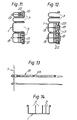
- Each retention unit includes two members, one is a cable retaining member of block- like form whilst the other is a locking member designed to hold the cable retaining member in a cable retaining position.
- Each retaining member is in the form of a plastic block 18 which is a push-fit into each channel and closely engages the internal flanks of its associated channel.
- the locking means can be in the form of a tie member 19 which projects from a central region of the base of a channel outwards into the channel.
- Each tie member can be formed of a resilient plastics material of a strip like form with a series of serrations 23 along its flanks.
- each block 18 has an aperture through its centre through which the tie member extends, the aperture being provided with ratchet means integrally formed with the block to resiliently engage the serrations on the tie member in such a way that once the block is inserted it cannot be removed without a special tool. Again, insertion is from the front.
- the tie member 19 may merely have anchorage means at one end which allows the tie member itself to protrude through a specially formed aperture in the base of the channel and the anchorage means engages with the base of the channel, in which case insertion would require to be from the rear of the raceway.
- the tie member 19 may have a spear or harpoon shaped arrangement at its anchorage end which allows insertion from the front of the raceway and also prevents easy removal.
- the cable holding capacity of a channel can be arranged such that the cable retaining block 18 lies flush with the channel mouth when the channel is full.
- the block is accordingly sized so that this can take place.
- the cable holding capacity may be arranged to be, say 10% greater than that initially required so that extra cables can be added.
- This extra capacity is shown cross hatched in Figures 11 and 12 for reference only.
- fairlead blocks can be inserted in the channel and held in by means of the blocks 18.
- Those fairlead blocks referenced 21 have apertures therein so that further cables can be passed through them and introduced into the channel as required.
- Those referenced 22 have open mouthed slots therein to accommodate the cables, the slots being closed by the walls of the channels 3 as the fairlead blocks are urged in and held by the blocks 18. This is a preferred arrangement since it facilitates the slipping in and out of cables during modifications to the cable runs.
- the fairlead blocks are incorporated into the retaining blocks 18 to provide a dual purpose block which performs both fairlead and retaining functions.
- the depth of the channels provides sufficient screening to prevent adverse interaction between cable runs.
- FIG 14 this illustrates, as an alternative embodiment, a further typical channel element of extruded cross-sectional form provided with a plurality of Channels 3.
- the interior of each channel is coated with PTFE to give both insulation and a low friction characteristic whilst additionally assisting in the avoidance of chaffing.
Landscapes
- Engineering & Computer Science (AREA)
- Architecture (AREA)
- Civil Engineering (AREA)
- Structural Engineering (AREA)
- Supports For Pipes And Cables (AREA)
- Details Of Indoor Wiring (AREA)
- Installation Of Indoor Wiring (AREA)
- Light Guides In General And Applications Therefor (AREA)
Applications Claiming Priority (2)
| Application Number | Priority Date | Filing Date | Title |
|---|---|---|---|
| GB848431067A GB8431067D0 (en) | 1984-12-08 | 1984-12-08 | Cable conduit system for vehicles |
| GB8431067 | 1984-12-08 |
Publications (3)
| Publication Number | Publication Date |
|---|---|
| EP0184931A2 true EP0184931A2 (de) | 1986-06-18 |
| EP0184931A3 EP0184931A3 (en) | 1988-09-07 |
| EP0184931B1 EP0184931B1 (de) | 1992-03-25 |
Family
ID=10570918
Family Applications (1)
| Application Number | Title | Priority Date | Filing Date |
|---|---|---|---|
| EP19850308896 Expired - Lifetime EP0184931B1 (de) | 1984-12-08 | 1985-12-06 | Kabelführungssystem für Fahrzeuge |
Country Status (7)
| Country | Link |
|---|---|
| US (1) | US4781255A (de) |
| EP (1) | EP0184931B1 (de) |
| JP (1) | JPS61180508A (de) |
| AU (1) | AU591078B2 (de) |
| DE (1) | DE3585725D1 (de) |
| ES (1) | ES8700508A1 (de) |
| GB (1) | GB8431067D0 (de) |
Cited By (14)
| Publication number | Priority date | Publication date | Assignee | Title |
|---|---|---|---|---|
| EP0588174A1 (de) * | 1992-09-15 | 1994-03-23 | DaimlerChrysler Aerospace Airbus Gesellschaft mit beschränkter Haftung | Leitungskanal zur Verlegung von isolierten elektrischen Leitungen |
| FR2905037A1 (fr) * | 2006-08-18 | 2008-02-22 | Airbus France Sas | Support pour cables destine notamment a la construction aeronautique. |
| FR2905039A1 (fr) * | 2006-08-17 | 2008-02-22 | Airbus France Sas | Support pour fixer des cables electriques sur une structure |
| FR2905038A1 (fr) * | 2006-08-18 | 2008-02-22 | Airbus France Sas | Systeme d'attache pour cables et support pour cables associe notamment pour la construction aeronautique. |
| FR2950490A1 (fr) * | 2009-09-23 | 2011-03-25 | Labinal | Chemin de cable pour aeronef a structure en materiau composite |
| US20110079429A1 (en) * | 2009-10-02 | 2011-04-07 | Labinal | Expandable cableway for aircraft with a structure made of composite material |
| CN102684116A (zh) * | 2011-03-17 | 2012-09-19 | 雷比诺公司 | 具有复合材料所制结构的飞行器缆道 |
| CN102684115A (zh) * | 2011-03-11 | 2012-09-19 | 雷比诺公司 | 将电缆固定至飞机结构的设备和扩容的方法及飞机机身 |
| FR2980313A1 (fr) * | 2011-09-21 | 2013-03-22 | Airbus Operations Sas | Dispositif de support de chemin de cables pour aeronef, notamment aeronef a structure au moins partiellement realisee dans un materiau composite |
| CN102684115B (zh) * | 2011-03-11 | 2016-12-14 | 雷比诺公司 | 将电缆固定至飞机结构的设备和扩容的方法及飞机机身 |
| EP3179585A1 (de) * | 2015-12-11 | 2017-06-14 | Airbus Operations Limited | Kabelkanal |
| FR3048311A1 (fr) * | 2016-02-26 | 2017-09-01 | Airbus Helicopters | Dispositif de protection de cable pour aeronef et aeronef |
| EP3222498A1 (de) * | 2016-03-21 | 2017-09-27 | Liebherr-Mischtechnik GmbH | Fahrmischer |
| EP4219294A1 (de) * | 2022-01-31 | 2023-08-02 | Airbus Operations Limited | Verbesserungen im zusammenhang mit der flügelkonstruktion |
Families Citing this family (19)
| Publication number | Priority date | Publication date | Assignee | Title |
|---|---|---|---|---|
| GB2166603B (en) * | 1984-09-28 | 1988-07-20 | Yazaki Corp | Electrical harness |
| JPH01106687U (de) * | 1988-01-09 | 1989-07-18 | ||
| JPH0733021Y2 (ja) * | 1988-02-16 | 1995-07-31 | 臼井国際産業株式会社 | クランプ体による配管の一括集中固定構造 |
| US5399812A (en) * | 1993-05-24 | 1995-03-21 | Chrysler Corporation | Housing for supporting and routing cables |
| US5354020A (en) * | 1993-05-28 | 1994-10-11 | Richards William J | Cable restraint system |
| DE19546781C1 (de) * | 1995-12-14 | 1997-07-24 | Euro Matsushita Electric Works | Gehäuse für eine Anschlußstelle in einer Flachbandleitung |
| DE19706288A1 (de) | 1997-02-18 | 1998-08-20 | Iro Ab | Meßliefergerät |
| US5811733A (en) * | 1997-07-16 | 1998-09-22 | Square D Company | Busway elbow device |
| WO2000002514A1 (en) * | 1998-07-08 | 2000-01-20 | Hill-Rom, Inc. | Head wall for a hospital room |
| US6380486B1 (en) * | 2000-04-13 | 2002-04-30 | The Wiremold Company | Divided raceway |
| WO2007134634A1 (de) * | 2006-05-18 | 2007-11-29 | Auto Kabel Managementgesellschaft Mbh | Stromprofil für kabeldurchführungen |
| GB0906071D0 (en) * | 2009-04-08 | 2009-05-20 | Airbus Uk Ltd | Cable raceway |
| US8783628B2 (en) * | 2010-03-26 | 2014-07-22 | Roger Jette | Flexible cable management system |
| GB2500669B (en) * | 2012-03-29 | 2016-03-30 | Icon Polymer Group | Hose for conveying fluid |
| US20160265693A1 (en) * | 2015-03-10 | 2016-09-15 | The Boeing Company | Duct assembly and method of assembling thereof |
| US11018484B2 (en) * | 2019-06-20 | 2021-05-25 | Oracle International Corporation | Serpentine comb assembly for cable management and retention via curve engagement |
| GB202005303D0 (en) * | 2020-04-09 | 2020-05-27 | Gripple Ltd | Anchor |
| US12318025B2 (en) * | 2020-09-25 | 2025-06-03 | Bote, Llc | Magnetic connection apparatus |
| FR3139247A1 (fr) * | 2022-08-23 | 2024-03-01 | Sagemcom Energy & Telecom Sas | Dispositif pour le blocage d’au moins un fil électrique et/ou d’au moins un câble sur un support dans un boitier |
Family Cites Families (14)
| Publication number | Priority date | Publication date | Assignee | Title |
|---|---|---|---|---|
| GB402555A (en) * | 1931-09-01 | 1933-12-07 | Jeumont Forges Const Elec | Metallic casing for electrical wiring |
| GB483589A (en) * | 1936-11-04 | 1938-04-22 | Henry Douglas Tindal Waldram | Improvements in casings for electric conductors |
| FR1158564A (fr) * | 1956-09-14 | 1958-06-17 | Gaine pour installations électriques | |
| US3346688A (en) * | 1964-11-12 | 1967-10-10 | Litton Systems Inc | Fork-type wiring harness |
| DE2103952A1 (de) * | 1971-01-28 | 1972-08-17 | Ver Flugtechnische Werke | Leitungskanal fur Rohre, elektn sehe Kabel oder dgl |
| FR2173452A5 (de) * | 1972-02-25 | 1973-10-05 | Morel Ets | |
| DE2226677C3 (de) * | 1972-05-31 | 1978-04-20 | Siemens Ag, 1000 Berlin Und 8000 Muenchen | Kabelhalterung |
| JPS518499U (de) * | 1974-07-04 | 1976-01-22 | ||
| JPS5632914U (de) * | 1979-08-22 | 1981-03-31 | ||
| US4372510A (en) * | 1980-08-04 | 1983-02-08 | The Budd Company | Wire raceway for attachment under the floor of a railway car |
| US4347998A (en) * | 1981-04-15 | 1982-09-07 | The Boeing Company | Multiple wire bundle support assembly |
| US4395009A (en) * | 1981-05-28 | 1983-07-26 | The Boeing Company | Raceway clamp |
| JPS59119723U (ja) * | 1983-01-31 | 1984-08-13 | 三菱重工業株式会社 | 電線固定バンド |
| US4589449A (en) * | 1984-08-23 | 1986-05-20 | Bramwell David W | Trunking |
-
1984
- 1984-12-08 GB GB848431067A patent/GB8431067D0/en active Pending
-
1985
- 1985-12-05 AU AU50803/85A patent/AU591078B2/en not_active Ceased
- 1985-12-06 ES ES549661A patent/ES8700508A1/es not_active Expired
- 1985-12-06 EP EP19850308896 patent/EP0184931B1/de not_active Expired - Lifetime
- 1985-12-06 DE DE8585308896T patent/DE3585725D1/de not_active Expired - Lifetime
- 1985-12-06 US US06/805,630 patent/US4781255A/en not_active Expired - Lifetime
- 1985-12-09 JP JP60276659A patent/JPS61180508A/ja active Granted
Cited By (25)
| Publication number | Priority date | Publication date | Assignee | Title |
|---|---|---|---|---|
| US5723819A (en) * | 1992-09-15 | 1998-03-03 | Daimler-Benz Aerospace Airbus Gmbh | Conductor channel for installing insulated electrical conductors |
| RU2134008C1 (ru) * | 1992-09-15 | 1999-07-27 | Дойче Эйроспейс Эйрбус ГмбХ | Кабельный канал для прокладки изолированных электрических линий |
| EP0588174A1 (de) * | 1992-09-15 | 1994-03-23 | DaimlerChrysler Aerospace Airbus Gesellschaft mit beschränkter Haftung | Leitungskanal zur Verlegung von isolierten elektrischen Leitungen |
| WO2008020147A3 (fr) * | 2006-08-17 | 2008-04-17 | Airbus France | Support pour fixer des cables electriques sur une structure |
| FR2905039A1 (fr) * | 2006-08-17 | 2008-02-22 | Airbus France Sas | Support pour fixer des cables electriques sur une structure |
| CN101523677B (zh) * | 2006-08-17 | 2012-04-25 | 空中客车运营简化股份公司 | 将电缆固定在结构体上的支座 |
| FR2905037A1 (fr) * | 2006-08-18 | 2008-02-22 | Airbus France Sas | Support pour cables destine notamment a la construction aeronautique. |
| US7692104B2 (en) | 2006-08-18 | 2010-04-06 | Airbus France | Attachment system for cables and support for cables used in aeronautic construction |
| FR2905038A1 (fr) * | 2006-08-18 | 2008-02-22 | Airbus France Sas | Systeme d'attache pour cables et support pour cables associe notamment pour la construction aeronautique. |
| FR2950490A1 (fr) * | 2009-09-23 | 2011-03-25 | Labinal | Chemin de cable pour aeronef a structure en materiau composite |
| US8540189B2 (en) | 2009-09-23 | 2013-09-24 | Labinal | Cable way for aircraft with a structure made of composite material |
| US20110079429A1 (en) * | 2009-10-02 | 2011-04-07 | Labinal | Expandable cableway for aircraft with a structure made of composite material |
| FR2951032A1 (fr) * | 2009-10-02 | 2011-04-08 | Labinal | Chemin de cable evolutif pour aeronef a structure en materiau composite |
| US8436245B2 (en) | 2009-10-02 | 2013-05-07 | Labinal | Expandable cableway for aircraft with a structure made of composite material |
| CN102684115B (zh) * | 2011-03-11 | 2016-12-14 | 雷比诺公司 | 将电缆固定至飞机结构的设备和扩容的方法及飞机机身 |
| CN102684115A (zh) * | 2011-03-11 | 2012-09-19 | 雷比诺公司 | 将电缆固定至飞机结构的设备和扩容的方法及飞机机身 |
| CN102684116A (zh) * | 2011-03-17 | 2012-09-19 | 雷比诺公司 | 具有复合材料所制结构的飞行器缆道 |
| FR2980313A1 (fr) * | 2011-09-21 | 2013-03-22 | Airbus Operations Sas | Dispositif de support de chemin de cables pour aeronef, notamment aeronef a structure au moins partiellement realisee dans un materiau composite |
| US9172230B2 (en) | 2011-09-21 | 2015-10-27 | Airbus Operations (S.A.S.) | Cable raceway support device for an aircraft, in particular an aircraft with a structure at least partly formed from a composite material |
| EP3179585A1 (de) * | 2015-12-11 | 2017-06-14 | Airbus Operations Limited | Kabelkanal |
| US10400918B2 (en) | 2015-12-11 | 2019-09-03 | Airbus Operations Limited | Raceway |
| FR3048311A1 (fr) * | 2016-02-26 | 2017-09-01 | Airbus Helicopters | Dispositif de protection de cable pour aeronef et aeronef |
| EP3222498A1 (de) * | 2016-03-21 | 2017-09-27 | Liebherr-Mischtechnik GmbH | Fahrmischer |
| EP4219294A1 (de) * | 2022-01-31 | 2023-08-02 | Airbus Operations Limited | Verbesserungen im zusammenhang mit der flügelkonstruktion |
| US12077287B2 (en) | 2022-01-31 | 2024-09-03 | Airbus Operations Limited | Wing construction |
Also Published As
| Publication number | Publication date |
|---|---|
| JPH0574286B2 (de) | 1993-10-18 |
| AU591078B2 (en) | 1989-11-30 |
| ES8700508A1 (es) | 1986-10-01 |
| AU5080385A (en) | 1986-06-12 |
| US4781255A (en) | 1988-11-01 |
| EP0184931B1 (de) | 1992-03-25 |
| DE3585725D1 (de) | 1992-04-30 |
| GB8431067D0 (en) | 1985-01-16 |
| JPS61180508A (ja) | 1986-08-13 |
| ES549661A0 (es) | 1986-10-01 |
| EP0184931A3 (en) | 1988-09-07 |
Similar Documents
| Publication | Publication Date | Title |
|---|---|---|
| EP0184931A2 (de) | Kabelführungssystem für Fahrzeuge | |
| FI66102B (fi) | Roer- och kabelbehaollare | |
| US6023024A (en) | Partition device for a cableway | |
| EP0116991B1 (de) | Sicherungshalter für Messerkontaktsicherung | |
| US5725185A (en) | Cable clamp bracket assembly | |
| US4919370A (en) | Cable fitting | |
| DE69618037T2 (de) | Kabelkanalsystem | |
| US6513764B2 (en) | Cable holder for attaching cables to a vehicle structure | |
| US5607126A (en) | Support and protection housing element for a tube, pipe, electric cable or other long article, particularly for a motor vehicle | |
| US20110303456A1 (en) | Modular conduit retention system | |
| EP0977335A2 (de) | Struktur zum Schutz eines biegsamen Flachkabels | |
| AU2006224441B2 (en) | Splice plate for a wire cable tray | |
| US5035645A (en) | Bracket for terminal block | |
| US3680817A (en) | Multi-way cable troughs | |
| GB2176451B (en) | An aerospace vehicle having multiple propulsion systems on a relatively rotatable flying wing | |
| US20120014745A1 (en) | Joint for extruded panels | |
| US20120015553A1 (en) | Housing formed from extruded panels | |
| CA2455371C (en) | Button fastening device | |
| US6325337B1 (en) | Connector for cable support apparatus | |
| US4234146A (en) | Flat type cable suspension structure | |
| EP0035516B1 (de) | Wand zum enteilen eines kanals für elektrische kabel in teilstrecken | |
| FI71639C (fi) | Stolpe eller balk foer foerande av kablar. | |
| CN219227156U (zh) | 一种船舶电气线路桥架 | |
| CN216851149U (zh) | 线缆夹持装置 | |
| DE4102318C2 (de) |
Legal Events
| Date | Code | Title | Description |
|---|---|---|---|
| PUAI | Public reference made under article 153(3) epc to a published international application that has entered the european phase |
Free format text: ORIGINAL CODE: 0009012 |
|
| 17P | Request for examination filed |
Effective date: 19860109 |
|
| AK | Designated contracting states |
Kind code of ref document: A2 Designated state(s): BE DE FR GB IT NL SE |
|
| PUAL | Search report despatched |
Free format text: ORIGINAL CODE: 0009013 |
|
| AK | Designated contracting states |
Kind code of ref document: A3 Designated state(s): BE DE FR GB IT NL SE |
|
| 17Q | First examination report despatched |
Effective date: 19900827 |
|
| RAP3 | Party data changed (applicant data changed or rights of an application transferred) |
Owner name: BRITISH AEROSPACE PUBLIC LIMITED COMPANY |
|
| ITF | It: translation for a ep patent filed | ||
| GRAA | (expected) grant |
Free format text: ORIGINAL CODE: 0009210 |
|
| AK | Designated contracting states |
Kind code of ref document: B1 Designated state(s): BE DE FR GB IT NL SE |
|
| ET | Fr: translation filed | ||
| REF | Corresponds to: |
Ref document number: 3585725 Country of ref document: DE Date of ref document: 19920430 |
|
| RAP4 | Party data changed (patent owner data changed or rights of a patent transferred) |
Owner name: BRITISH AEROSPACE PUBLIC LIMITED COMPANY |
|
| ITTA | It: last paid annual fee | ||
| PLBE | No opposition filed within time limit |
Free format text: ORIGINAL CODE: 0009261 |
|
| STAA | Information on the status of an ep patent application or granted ep patent |
Free format text: STATUS: NO OPPOSITION FILED WITHIN TIME LIMIT |
|
| 26N | No opposition filed | ||
| EAL | Se: european patent in force in sweden |
Ref document number: 85308896.1 |
|
| NLT1 | Nl: modifications of names registered in virtue of documents presented to the patent office pursuant to art. 16 a, paragraph 1 |
Owner name: BAE SYSTEMS PLC |
|
| REG | Reference to a national code |
Ref country code: GB Ref legal event code: IF02 |
|
| REG | Reference to a national code |
Ref country code: GB Ref legal event code: 732E |
|
| BECA | Be: change of holder's address |
Free format text: 20020806 *AIRBUS UK LTD:NEW FILTON HOUSE, GB - FILTON, BRISTOL BS99 7AR |
|
| REG | Reference to a national code |
Ref country code: FR Ref legal event code: TP |
|
| NLS | Nl: assignments of ep-patents |
Owner name: AIRBUS UK LIMITED |
|
| PGFP | Annual fee paid to national office [announced via postgrant information from national office to epo] |
Ref country code: FR Payment date: 20031110 Year of fee payment: 19 |
|
| PGFP | Annual fee paid to national office [announced via postgrant information from national office to epo] |
Ref country code: NL Payment date: 20031117 Year of fee payment: 19 |
|
| PGFP | Annual fee paid to national office [announced via postgrant information from national office to epo] |
Ref country code: SE Payment date: 20031118 Year of fee payment: 19 Ref country code: GB Payment date: 20031118 Year of fee payment: 19 |
|
| PGFP | Annual fee paid to national office [announced via postgrant information from national office to epo] |
Ref country code: DE Payment date: 20031125 Year of fee payment: 19 |
|
| PGFP | Annual fee paid to national office [announced via postgrant information from national office to epo] |
Ref country code: BE Payment date: 20031217 Year of fee payment: 19 |
|
| PG25 | Lapsed in a contracting state [announced via postgrant information from national office to epo] |
Ref country code: GB Free format text: LAPSE BECAUSE OF NON-PAYMENT OF DUE FEES Effective date: 20041206 |
|
| PG25 | Lapsed in a contracting state [announced via postgrant information from national office to epo] |
Ref country code: SE Free format text: LAPSE BECAUSE OF NON-PAYMENT OF DUE FEES Effective date: 20041207 |
|
| PG25 | Lapsed in a contracting state [announced via postgrant information from national office to epo] |
Ref country code: BE Free format text: LAPSE BECAUSE OF NON-PAYMENT OF DUE FEES Effective date: 20041231 |
|
| BERE | Be: lapsed |
Owner name: *AIRBUS UK LTD Effective date: 20041231 |
|
| PG25 | Lapsed in a contracting state [announced via postgrant information from national office to epo] |
Ref country code: NL Free format text: LAPSE BECAUSE OF NON-PAYMENT OF DUE FEES Effective date: 20050701 Ref country code: DE Free format text: LAPSE BECAUSE OF NON-PAYMENT OF DUE FEES Effective date: 20050701 |
|
| GBPC | Gb: european patent ceased through non-payment of renewal fee |
Effective date: 20041206 |
|
| EUG | Se: european patent has lapsed | ||
| PG25 | Lapsed in a contracting state [announced via postgrant information from national office to epo] |
Ref country code: FR Free format text: LAPSE BECAUSE OF NON-PAYMENT OF DUE FEES Effective date: 20050831 |
|
| NLV4 | Nl: lapsed or anulled due to non-payment of the annual fee |
Effective date: 20050701 |
|
| REG | Reference to a national code |
Ref country code: FR Ref legal event code: ST |
|
| BERE | Be: lapsed |
Owner name: *AIRBUS UK LTD Effective date: 20041231 |