EP0184949B2 - Méthode de régénération de pièces en superalliage base nickel en fin de potentiel de fonctionnement - Google Patents
Méthode de régénération de pièces en superalliage base nickel en fin de potentiel de fonctionnement Download PDFInfo
- Publication number
- EP0184949B2 EP0184949B2 EP85402131A EP85402131A EP0184949B2 EP 0184949 B2 EP0184949 B2 EP 0184949B2 EP 85402131 A EP85402131 A EP 85402131A EP 85402131 A EP85402131 A EP 85402131A EP 0184949 B2 EP0184949 B2 EP 0184949B2
- Authority
- EP
- European Patent Office
- Prior art keywords
- temperature
- rejuvenation
- cooling
- creep
- nickel
- Prior art date
- Legal status (The legal status is an assumption and is not a legal conclusion. Google has not performed a legal analysis and makes no representation as to the accuracy of the status listed.)
- Expired - Lifetime
Links
- 238000000034 method Methods 0.000 title claims description 24
- PXHVJJICTQNCMI-UHFFFAOYSA-N Nickel Chemical compound [Ni] PXHVJJICTQNCMI-UHFFFAOYSA-N 0.000 title claims description 18
- 229910052759 nickel Inorganic materials 0.000 title claims description 9
- 230000003716 rejuvenation Effects 0.000 title claims description 6
- 229910000601 superalloy Inorganic materials 0.000 title description 4
- 229910045601 alloy Inorganic materials 0.000 claims description 24
- 239000000956 alloy Substances 0.000 claims description 24
- 238000011282 treatment Methods 0.000 claims description 21
- 238000001816 cooling Methods 0.000 claims description 18
- 238000001556 precipitation Methods 0.000 claims description 10
- 230000005496 eutectics Effects 0.000 claims description 9
- 239000000203 mixture Substances 0.000 claims description 6
- 229910052804 chromium Inorganic materials 0.000 claims description 5
- 229910052799 carbon Inorganic materials 0.000 claims description 4
- 229910052719 titanium Inorganic materials 0.000 claims description 4
- 238000005056 compaction Methods 0.000 claims description 3
- 229910052750 molybdenum Inorganic materials 0.000 claims description 3
- 238000010790 dilution Methods 0.000 claims description 2
- 239000012895 dilution Substances 0.000 claims description 2
- 229910052720 vanadium Inorganic materials 0.000 claims description 2
- 239000011253 protective coating Substances 0.000 claims 1
- 238000012360 testing method Methods 0.000 description 15
- 239000012071 phase Substances 0.000 description 14
- 150000001247 metal acetylides Chemical class 0.000 description 11
- 230000008929 regeneration Effects 0.000 description 9
- 238000011069 regeneration method Methods 0.000 description 9
- 238000004581 coalescence Methods 0.000 description 8
- 238000010438 heat treatment Methods 0.000 description 8
- 239000011159 matrix material Substances 0.000 description 6
- 238000009792 diffusion process Methods 0.000 description 5
- 239000002244 precipitate Substances 0.000 description 5
- 230000035882 stress Effects 0.000 description 5
- XKRFYHLGVUSROY-UHFFFAOYSA-N Argon Chemical compound [Ar] XKRFYHLGVUSROY-UHFFFAOYSA-N 0.000 description 4
- 229910052782 aluminium Inorganic materials 0.000 description 4
- XAGFODPZIPBFFR-UHFFFAOYSA-N aluminium Chemical compound [Al] XAGFODPZIPBFFR-UHFFFAOYSA-N 0.000 description 4
- 239000011651 chromium Substances 0.000 description 4
- 230000007797 corrosion Effects 0.000 description 4
- 238000005260 corrosion Methods 0.000 description 4
- 230000000694 effects Effects 0.000 description 4
- 230000001376 precipitating effect Effects 0.000 description 4
- 230000008034 disappearance Effects 0.000 description 3
- 238000012423 maintenance Methods 0.000 description 3
- 239000000463 material Substances 0.000 description 3
- 239000000243 solution Substances 0.000 description 3
- 239000000126 substance Substances 0.000 description 3
- 239000010936 titanium Substances 0.000 description 3
- OKTJSMMVPCPJKN-UHFFFAOYSA-N Carbon Chemical compound [C] OKTJSMMVPCPJKN-UHFFFAOYSA-N 0.000 description 2
- NPXOKRUENSOPAO-UHFFFAOYSA-N Raney nickel Chemical compound [Al].[Ni] NPXOKRUENSOPAO-UHFFFAOYSA-N 0.000 description 2
- 229910052786 argon Inorganic materials 0.000 description 2
- 150000001875 compounds Chemical class 0.000 description 2
- 210000001787 dendrite Anatomy 0.000 description 2
- 239000010419 fine particle Substances 0.000 description 2
- 239000007789 gas Substances 0.000 description 2
- 239000010410 layer Substances 0.000 description 2
- 229910000907 nickel aluminide Inorganic materials 0.000 description 2
- 230000003647 oxidation Effects 0.000 description 2
- 238000007254 oxidation reaction Methods 0.000 description 2
- 239000011148 porous material Substances 0.000 description 2
- 230000001681 protective effect Effects 0.000 description 2
- 239000011241 protective layer Substances 0.000 description 2
- 230000001172 regenerating effect Effects 0.000 description 2
- 238000007711 solidification Methods 0.000 description 2
- 230000008023 solidification Effects 0.000 description 2
- 238000005496 tempering Methods 0.000 description 2
- IRPGOXJVTQTAAN-UHFFFAOYSA-N 2,2,3,3,3-pentafluoropropanal Chemical compound FC(F)(F)C(F)(F)C=O IRPGOXJVTQTAAN-UHFFFAOYSA-N 0.000 description 1
- 229910000951 Aluminide Inorganic materials 0.000 description 1
- KLZUFWVZNOTSEM-UHFFFAOYSA-K Aluminum fluoride Inorganic materials F[Al](F)F KLZUFWVZNOTSEM-UHFFFAOYSA-K 0.000 description 1
- ZAMOUSCENKQFHK-UHFFFAOYSA-N Chlorine atom Chemical compound [Cl] ZAMOUSCENKQFHK-UHFFFAOYSA-N 0.000 description 1
- VYZAMTAEIAYCRO-UHFFFAOYSA-N Chromium Chemical compound [Cr] VYZAMTAEIAYCRO-UHFFFAOYSA-N 0.000 description 1
- PXGOKWXKJXAPGV-UHFFFAOYSA-N Fluorine Chemical compound FF PXGOKWXKJXAPGV-UHFFFAOYSA-N 0.000 description 1
- ZOKXTWBITQBERF-UHFFFAOYSA-N Molybdenum Chemical compound [Mo] ZOKXTWBITQBERF-UHFFFAOYSA-N 0.000 description 1
- 241000135309 Processus Species 0.000 description 1
- NINIDFKCEFEMDL-UHFFFAOYSA-N Sulfur Chemical compound [S] NINIDFKCEFEMDL-UHFFFAOYSA-N 0.000 description 1
- 238000003917 TEM image Methods 0.000 description 1
- RTAQQCXQSZGOHL-UHFFFAOYSA-N Titanium Chemical compound [Ti] RTAQQCXQSZGOHL-UHFFFAOYSA-N 0.000 description 1
- 229910011214 Ti—Mo Inorganic materials 0.000 description 1
- 238000004873 anchoring Methods 0.000 description 1
- 230000015572 biosynthetic process Effects 0.000 description 1
- 238000005266 casting Methods 0.000 description 1
- 230000015556 catabolic process Effects 0.000 description 1
- 238000006243 chemical reaction Methods 0.000 description 1
- 239000000460 chlorine Substances 0.000 description 1
- 229910052801 chlorine Inorganic materials 0.000 description 1
- 239000011362 coarse particle Substances 0.000 description 1
- 239000011248 coating agent Substances 0.000 description 1
- 238000000576 coating method Methods 0.000 description 1
- 239000010941 cobalt Substances 0.000 description 1
- 229910017052 cobalt Inorganic materials 0.000 description 1
- GUTLYIVDDKVIGB-UHFFFAOYSA-N cobalt atom Chemical compound [Co] GUTLYIVDDKVIGB-UHFFFAOYSA-N 0.000 description 1
- 230000002301 combined effect Effects 0.000 description 1
- 239000000567 combustion gas Substances 0.000 description 1
- 238000002485 combustion reaction Methods 0.000 description 1
- 230000000052 comparative effect Effects 0.000 description 1
- 230000006835 compression Effects 0.000 description 1
- 238000007906 compression Methods 0.000 description 1
- 239000000470 constituent Substances 0.000 description 1
- 235000019628 coolness Nutrition 0.000 description 1
- 230000007423 decrease Effects 0.000 description 1
- 230000003247 decreasing effect Effects 0.000 description 1
- 238000006731 degradation reaction Methods 0.000 description 1
- 230000006866 deterioration Effects 0.000 description 1
- 230000001627 detrimental effect Effects 0.000 description 1
- 238000011161 development Methods 0.000 description 1
- 230000018109 developmental process Effects 0.000 description 1
- 238000004090 dissolution Methods 0.000 description 1
- 238000009826 distribution Methods 0.000 description 1
- 238000002474 experimental method Methods 0.000 description 1
- 230000002349 favourable effect Effects 0.000 description 1
- 239000011737 fluorine Substances 0.000 description 1
- 229910052731 fluorine Inorganic materials 0.000 description 1
- 239000011261 inert gas Substances 0.000 description 1
- 230000000977 initiatory effect Effects 0.000 description 1
- 229910000765 intermetallic Inorganic materials 0.000 description 1
- 230000007774 longterm Effects 0.000 description 1
- 238000004519 manufacturing process Methods 0.000 description 1
- 230000007246 mechanism Effects 0.000 description 1
- 238000002844 melting Methods 0.000 description 1
- 230000008018 melting Effects 0.000 description 1
- 229910052751 metal Inorganic materials 0.000 description 1
- 239000002184 metal Substances 0.000 description 1
- 238000010310 metallurgical process Methods 0.000 description 1
- 238000001000 micrograph Methods 0.000 description 1
- 239000011733 molybdenum Substances 0.000 description 1
- 238000005457 optimization Methods 0.000 description 1
- 239000007800 oxidant agent Substances 0.000 description 1
- 238000010791 quenching Methods 0.000 description 1
- 238000010583 slow cooling Methods 0.000 description 1
- 239000006104 solid solution Substances 0.000 description 1
- 239000000758 substrate Substances 0.000 description 1
- 229910052717 sulfur Inorganic materials 0.000 description 1
- 239000011593 sulfur Substances 0.000 description 1
- 238000010408 sweeping Methods 0.000 description 1
- 230000009897 systematic effect Effects 0.000 description 1
- 238000002076 thermal analysis method Methods 0.000 description 1
- 230000008646 thermal stress Effects 0.000 description 1
- 238000007669 thermal treatment Methods 0.000 description 1
- LEONUFNNVUYDNQ-UHFFFAOYSA-N vanadium atom Chemical compound [V] LEONUFNNVUYDNQ-UHFFFAOYSA-N 0.000 description 1
- 239000012808 vapor phase Substances 0.000 description 1
- 229910052726 zirconium Inorganic materials 0.000 description 1
Images

Classifications
-
- C—CHEMISTRY; METALLURGY
- C22—METALLURGY; FERROUS OR NON-FERROUS ALLOYS; TREATMENT OF ALLOYS OR NON-FERROUS METALS
- C22F—CHANGING THE PHYSICAL STRUCTURE OF NON-FERROUS METALS AND NON-FERROUS ALLOYS
- C22F1/00—Changing the physical structure of non-ferrous metals or alloys by heat treatment or by hot or cold working
- C22F1/10—Changing the physical structure of non-ferrous metals or alloys by heat treatment or by hot or cold working of nickel or cobalt or alloys based thereon
Definitions
- the invention relates to a method of heat treatment for parts arriving at the end of operating potential after having undergone damage by creep in particular; the aim of the method is to make them recover their initial properties in order to prolong their lifespan. It relates to parts made of heat resistant alloy with a nickel base comprising a hardening phase y ′ and applies in particular to the moving blades of a turbomachine.
- the blades must be able to resist creep at high temperature because they are mounted on a disc rotating between 5,000 and 20,000 rpm while being exposed to hot gases from 900 ° C to 1300 ° C and oxidants leaving the combustion chamber .
- the nickel-based superalloys used in aeronautics have a hardening phase y ′, the volume fraction of which can reach 70%.
- the blades subjected to such mechanical and thermal stresses undergo permanent elongation by creep which inevitably leads to their systematic scrapping after a certain number of hours of use in order to avoid the risks of catastrophic rupture.
- the high pressure turbine blades of a certain number of engines currently have their operating potential limited to about 800 hours by creep.
- This creep deformation process resulting in a degradation of the microcrystalline structure is the production of a heat treatment method allowing the restoration of the initial structure under conditions compatible with the geometrical criteria of the parts.
- the invention therefore has the second objective of carrying out a heat treatment which does not require the prior operation of removing the protective layer.
- the method of regenerating parts of heat-resistant alloy based on nickel NK15 CAT comprising in particular Co 13 to 17%, Cr 8 to 11%, Ai 5 to 6%, Ti 4 to 5%, Mo 2 at 4%, Va 0.7 to 1.7%, C 0.1 to 0.2% and forming an eutectic yy 'comprising a hardening phase y', the part having consumed at least part of its operating potential at cause in particular of damage by creep at high temperature, consists in maintaining the part at a temperature between 1160 ° C and 1220 ° C and for a period between 1 h and 4 h to re-dissolve at least 50% of phase y ′, the method consists in subsequently cooling the part at a controlled speed to a temperature below 700 ° C. corresponding to the precipitation range of phase y ′, this speed being chosen as a function
- patent FR 2 292 049 describes a method for extending the duration of the secondary creep of certain alloys; it consists of an unconstrained heat treatment, carried out at a temperature lower than that of dissolution of the compounds.
- This temperature corresponds in practice to the maximum operating temperature of the room; moreover, maintaining the temperature is quite long because, according to the hypothesis put forward, it should allow the annihilation of the lacunar networks by a diffusion process.
- This treatment limited in temperature, is certainly ineffective for parts having operated at high temperatures, such as 1100 ° C., because it does not allow the regeneration of the microcrystalline structure because it excludes the re-solution of the hardening compounds. .
- its duration makes it economically uninteresting in an industrial application.
- Patent FR 2 313 459 relates to a method for improving the service performance of metal parts which have undergone permanent elongation. It consists in subjecting these parts, before the appearance of surface cracks, to hot isostatic compression, at a temperature lower than that where a magnification of the grains occurs, then to apply a treatment of re-solution of the phases followed by 'a hardening income.
- the major advantage of compaction lies in the fact that it closes the creep decohesions and the non-opening foundry pores.
- the IN 100 alloy of formula NK 15 CAT is a nickel-base cast alloy. Its composition is as follows: Cobalt 13 to 17%, Chromium 8 to 11%, aluminum 5 to 6%, titanium 4 to 5%, molybdenum 2 to 4%, vanadium 0.7 to 1.7%, Carbon 0.1 at 0.2% etc ...
- the IN 100 is designed for long-term use at 1000 ° C and 1100 ° C for short-term. In all cases, its poor resistance to corrosion, in particular in a sulfurous atmosphere, requires protection, obtained for example by the vapor phase aluminization method of patent FR 1 433 497.
- the IN 100 has a dendritic structure y-y 'decorated by eutectic aggregates and carbides.
- the size of the basalt grain dendrites and the morphology of the hardening phase depend on the rate of cooling on casting, therefore on the local thickness of material in the part, and on the content of B and Zr. It varies from a few tenths to several mm for thicknesses ranging from 1 to 10 mm.
- the matrix y hardened by the effect of a solid solution of Cr and Co in Ni crystallizes in the CFC system
- the maximum hardening comes from the precipitation of the phase y ', ordered, of type L1 2 (Cu 3 Au) of the same crystalline system and consistent with the matrix. Its volume fraction is around 70%.
- the approximate composition is (Ni, Co) 3 (T, AI).
- the exceptional mechanical resistance when hot gives y 'to nickel-based superalloys comes essentially from the flow stress of this phase which has the remarkable property of increasing when the temperature increases.
- the alloy is rich in eutectic flows y-y ', located in interdendritic spaces.
- the temperature of formation of these aggregates is linked to their chemistry during the passage of the solidus, and can vary within wide proportions.
- the thermal analysis places it between 1210 and 1275 ° C depending in particular on the carbon content.
- the new dawn presents at the leading edge as at the trailing edge a structure y-y 'rich in eutectics and primary carbides.
- y' coarse 'of size close to 2 f..lm precipitating shortly after the solidification of the alloy
- fine of size close to 0.2 f .. lm precipitating during cooling following the protective treatment.
- the primary carbides precipitating while the alloy is not fully solidified, are repelled in the interdendritic sites where the grain boundaries are located, which are essentially distinguished by the difference in orientation of the y 'between 2 contiguous grains.
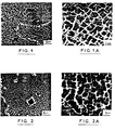
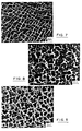
- the first microstructural evolution observed consists in the precipitation of secondary intergranular carbides, around the primary carbides and at the interfaces y-y 'of the eutectics, after 50 h of operation (FIGS. 1 and 1 A).
- the precipitation intensifies to become intragranular.
- phenomena of coalescence of the phase y ' cause the gradual disappearance of the precipitated ends y'.
- the size of the globules reaches 3 to 4 ⁇ m there and can double in the vicinity of eutectics, primary carbides and grain boundaries ( Figures 2 and 2A).
- the microstructure at the leading edge in the middle of the blade has a dendritic appearance.
- the interdendritic spaces are rich in eutectic and consist of precipitates y 'substantially larger than in the heart of the dendrites.
- the geometry of certain foundry pores reveals a beginning of deformation, as already observed after 800 hours; the coalescence of the y 'phase causes the disappearance of the fine precipitates.
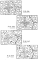
- FIGS. 5A to D give in summary a schematic representation of the process of damage by creep of the alloy subjected to a stress of 130 MPa and a temperature of 1000 ° C., in particular observed on test pieces.
- FIG. 5A shows the state of the structure after aluminization, there are 3 populations of y ′: relatively coarse particles of interdendritic y ′, fine particles of y ′ dendritic and very fine particles uniformly distributed obtained during cooling after aluminization treatment.
- the invention relates to a known type of process in which the alloy is subjected to a creep potential regeneration treatment comprising a thermal cycle erasing the microstructural effects of the deformation and leading to a microstructure approaching that of the alloy before stress.
- the part to be treated as observed, that is to say after 1000 hours of operation, is placed in an oven, preferably under vacuum in order to overcome oxidation problems. It is heated to a chosen temperature to re-dissolve a sufficient volume fraction of the hardening phase. In the present case of IN 100 alloy vanes protected by aluminization, this temperature is also determined as a function of its compatibility with maintaining the protection; in fact a too high temperature would cause the diffusion of aluminum and the dilution of the layer of nickel aluminide.
- this temperature was chosen at 1190 ° C but may vary depending on the case between 1160 ° C and 1220 ° C.
- the choice of temperature is also guided by the need for a sufficient margin with the melting temperature of the eutecti than for industrial application.
- the part was cooled by injecting a flow of inert gas, argon, into the oven. We controlled the flow in order to control the cooling rate of the room.
- the part is cooled by controlling the cooling rate to a temperature below 700 ° C corresponding to the precipitation range of phase y '.
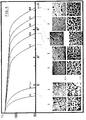
- the set of microstructures obtained is represented in FIG. 6. It is observed that the argon coolings lead to the precipitation of two populations of y ', and that the volume fraction of "large” y' increases while the content of fine constituents decreases , while decreasing the cooling rate. Microstructural observation reveals a complex phenomenon of "germination-growing” and “growth-coalescence", the respective kinetics of which vary according to the local chemical composition of the matrix giving rise to y '. There is therefore a compromise between the volume fractions of large y 'and of fine y' allowing the best mechanical behavior to be obtained as a function of the criteria sought.
- the cooling rate is controlled between 1085 ° C / h and 1145 ° C / h which leads to the microstructure of Figure 9. Under these conditions, it is no longer possible to differentiate a new blade ( Figure 7) of a regenerated blade (FIG. 9) by the sole examination of their microstructure: distribution of ⁇ - ⁇ 'identical in the two cases, absence of secondary carbides, the latter having been dissolved during the treatment.
- Tests were also carried out on test pieces in order to characterize them in creep.
- the IN 100 alloy test pieces underwent: 0.5%, 1% and 3% elongation under a stress of 130 MPa at 1000 ° C; in engine operating equivalent, 1% elongation is equivalent to 800 hours of operation for the above conditions.
- the test pieces are regenerated and then reassembled in creep.
- the test results are shown in FIG. 10. It is observed that, under the test conditions, the alloy present after regeneration of the primary and secondary cloud stages, the smaller the pre-deformation.
- the maximum gain in treatment is obtained after a pre-deformation of 0.5%.
- the time to obtain 1% elongation is 83 ⁇ 10 hours, the time to obtain this same elongation after treatment with 0.5% elongation increases to 103 ⁇ 16 hours, ie a gain of 24% .
- the gain is similar on the break time. It is 145 hours normally and goes to 180 hours after regeneration at 0.5% elongation.
Landscapes
- Chemical & Material Sciences (AREA)
- Mechanical Engineering (AREA)
- Thermal Sciences (AREA)
- Crystallography & Structural Chemistry (AREA)
- Engineering & Computer Science (AREA)
- Materials Engineering (AREA)
- Physics & Mathematics (AREA)
- Metallurgy (AREA)
- Organic Chemistry (AREA)
- Turbine Rotor Nozzle Sealing (AREA)
- Manufacture And Refinement Of Metals (AREA)
- Chemically Coating (AREA)
- Solid-Sorbent Or Filter-Aiding Compositions (AREA)
Description
- L'invention se rapporte à une méthode de traitement thermique pour des pièces arrivant en fin de potentiel de fonctionnement après avoir subi un endommagement par fluage notamment; le but de la méthode est de leur faire récupérer leurs propriétés initiales afin d'en prolonger la durée de vie. Elle concerne les pièces en alliage résistant à chaud à base nickel comportant une phase durcissante y' et s'applique en particulier aux aubes mobiles de turbomachine.
- Les aubes doivent pouvoir résister au fluage à haute température car elles sont montées sur un disque tournant entre 5 000 et 20 000 t/mn tout en étant exposées aux gaz chauds de 900 °C à 1300 °C et oxydants sortant de la chambre de combustion. On s'est donc orienté vers les alliages coulés, permettant l'optimisation de leur composition chimique et susceptible d'un durcissement important par précipitation en vue d'améliorer la résistance à la rupture par fluage. Les superalliages à base nickel utilisés en aéronautique comportent une phase durcissante y' dont la fraction volumique peut atteindre 70 %.
- Cependant en cours de fonctionnement les aubes soumises à de tels efforts mécaniques et thermiques subissent un allongement permanent par fluage qui conduit fatalement à leur mise au rebut systématique après un certain nombre d'heures d'utilisation afin d'éviter les risques de rupture catastrophique. Par exemple les aubes de turbine haute pression d'un certain nombre de moteurs voient actuellement leur potentiel de fonctionnement limité à 800 heures environ par le fluage.
- Ce processus de déformation par fluage se traduisant par une dégradation de la structure microcristalline l'invention a pour objet la réalisation d'une méthode de traitement thermique permettant la restauration de la structure initiale dans des conditions compatibles avec les critères géométriques des pièces.
- Ces alliages conçus pour une utilisation à haute température présentent une mauvaise tenue à la corrosion au-delà de 900 °C, notamment en atmosphère sulfurante ; ils nécessitent donc une protection superficielle qui peut être un revêtement d'aluminiure de nickel obtenu par voie thermochimique. Le problème posé par ce type de protection est qu'un traitement thermique de la pièce au-delà d'une certaine température et d'une certaine durée entraîne une diffusion inter-métallique modifiant sa composition chimique et ses propriétés. Pour éviter ceci, il suffit normalement d'un traitement préalable d'enlèvement de cette couche. Mais cette opération est apparue impossible sur des aubes de turbine pourvues de canaux interries de refroidissement car elle réduirait de façon prohibitive leur épaisseur de parois déjà minces.
- L'invention a donc pour second objectif la réalisation d'un traitement thermique ne nécessitant pas l'opération préalable d'enlèvement de la couche de protection. Conformément à l'invention, la méthode de régénération de pièces en alliage résistant à chaud à base nickel NK15 CAT comportant notamment Co 13 à 17 %, Cr 8 à 11 %, Ai 5 à 6 %, Ti 4 à 5 %, Mo 2 à 4 %, Va 0,7 à 1,7 %, C 0,1 à 0,2 % et formant un eutectique y-y' comportant une phase durcissante y', la pièce ayant consommé une partie au moins de son potentiel de fonctionnement à cause notamment d'un endommagement par fluage à température élevée, consiste à maintenir la pièce à une température comprise entre 1160 °C et 1 220 °C et pendant une durée comprise entre 1 h et 4 h pour remettre en solution au moins 50 % de la phase y', la méthode consiste à refroidir ensuuite la pièce à vitesse contrôlée jusqu'à une température inférieure à 700°C correspondant au domaine de précipitation de la phase y', cette vitesse étant choisie en fonction de la morphologie microatructurale désirée.
- Lors de travaux antérieurs, des traitements de régénération ont déjà été mis au point. Par exemple le brevet FR 2 292 049 décrit un procédé pour prolonger la durée du fluage secondaire de certains alliages ; il consiste en un traitement thermique sans contrainte, mené à une température inférieure à celle de mise en solution des composés. Cette température correspond dans la pratique à la température maximale de fonctionnement de la pièce ; par ailleurs le maintien en température est assez long car il doit permettre, selon l'hypothèse émise, l'annihilation des réseaux lacunaires par un processus de diffusion. Ce traitement, limité en température, est certainement inéfficace pour des pièces ayant fonctionné à de hautes températures, telle que 1100°C, car il ne permet pas la régénération de la structure microcristalline du fait qu'il exclut la remise en solution des composés durcissants. De plus sa durée le rend économiquement inintéressant dans une application industrielle.
- Le document "Rejuvenation of turbine blade material by thermal treatment", Final Report for Air Force Wright Patterson AFB, ohio 4533 de Juillet 1979 prévoit une méthode de régénération d'aubes après fluage comportant un premier traitement thermique à une température inférieure ou égale à 1149°C pendant 2 à 4h suivi d'un revenu à une température inférieure à 927° pendant 10 à 12h puis d'un refroidisaement à l'air.
- Par ailleurs, le document "The Creep and Fracture Behaviour of the Cost, Nickel based Superalloy IN1003, Materials Science and Engineering, 33 (1978) de J.P. Dennisan, P.D Holmes et B. Wilshise, décrit un procédé, sensiblement voisin du précédent, permettant une augmentation de la durée de vie au fluage. Ce procédé comporte quatre étapes :
- - maintien à température de 1220°C pendant une heure
- -refroidissement à vitesse de 0,1°C/S jusqu'à 900°C
- - traitement de revenu à 1100°C pendant 1 heure
- - refroidissement à une vitesse de 4°C/s soit 1400°C/h, c'est à dire un passage à la température ambiante en 270 secondes, soit 4 minutes.
- C'est dernière étape étant en fait une trempe.
- Le brevet FR 2 313 459 porte sur un procédé d'amélioration de la tenue en service de pièces métalliques ayant subi un allongement permanent. Il consiste à soumettre ces pièces, avant l'apparition de criques de surface, à une compression isostatique à chaud, à une température inférieure à celle où se produit un grossissement des grains, puis à appliquer un traitement de remise en solution des phases suivi d'un revenu de durcissement. L'intérêt majeur du compactage réside dans le fait qu'il referme les décohésions de fluage et les pores de fonderie non débou- chants.
- Cette technique est cependant de mise en oeuvre assez lourde, elle ne se justifie pas dans tous les cas. De plus le traitement thermique qui suit ne permet pas de maitriser les mécanismes de précipitation ; il ne tient pas compte non plus d'une détérioration de la couche de protection en surface ; enfin il ne permet pas une application industrielle économique.
- La description qui suit permettra de mieux comprendre l'invention et ses avantages par rapport à l'art antérieur. Elle se réfère à l'alliage de dénomination commerciale IN 100 mais on comprendra que la méthode est plus générale et sa portée ne se limite pas à cet alliage.
- - Les figures 1 et 1A sont des microphotographies réalisées au microscope électronique d'une aube après 50 heures de fonctionnement sur moteur.
- - Les figures 2 et 2A sont des microphotographies analogues aux précédentes pour une aube ayant fonctionné 800 heures.
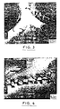
- - Les figures 3 et 4 sont des microphotographies révélant l'aspect des dislocations d'interface y-y' après 800 heures de fonctionnement.
- - Les figures 5A à D donnent une représentation schématique du processus d'endommagement par fluage.
- - La figure 6 montre l'évolution microstructurale de l'alliage en fonction de la vitesse de refroidissement après un maintien à 1190 °C pendant 1 heure sous vide.
- - Les figures 7, 8 et 9 montrent l'effet microstructural du traitement de régénération : la figure 7 est une microphotographie d'une aube neuve, la figure 8 d'une aube ayant fonctionné 1000 heures et la figure 9 d'une aube régénérée après 1000 heures de fonctionnement.
- - la figure 10 représente dans un repère temps- allongement le comportement en fluage d'une éprouvette respectivement sans régénération et avec régénération à 0,5 % d'allongement.
- L'alliage IN 100 de formule NK 15 CAT est un alliage coulé base nickel. Sa composition est la suivante : Cobalt 13 à 17 %, Chrome 8 à 11 %, aluminium 5 à 6 %, titane 4 à 5 %, molybdène 2 à 4 %, vanadium 0,7 à 1,7 %, Carbone 0,1 à 0,2 % etc...
- Coulé sous vide à 1460 °C, l'lN 100 est conçu pour une utilisation longue durée à 1000 °C et 1100 °C en courte durée. Dans tous les cas, sa mauvaise tenue à la corrosion, notamment en atmosphère sulfurante, nécessite une protection, obtenue par exemple par la méthode d'aluminisation en phase vapeur du brevet FR 1 433 497.
- D'un point de vue microstructural, l'lN 100 présente une structure dendritique y-y' décorée par des agrégats eutectiques et des carbures. La taille des dendrites du grain basaltique et la morphologie de la phase durcissante dépendent de la vitesse de refroidissement à la coulée, donc de l'épaisseur locale de matière dans la pièce, et de la teneur en B et Zr. Elle évolue de quelques dixièmes à plusieurs mm pour des épaisseurs allant de 1 à 10 mm.
- La matrice y, durcie par effet de solution solide de Cr et Co dans le Ni cristallise dans le système C.F.C. Le durcissement maximal provient de la précipitation de la phase y', ordonnée, de type L12(Cu3Au) de même système cristallin et en cohérence avec la matrice. Sa fraction volumique est d'environ 70 %. La composition approximative est (Ni, Co)3 (T, AI). La résistance mécanique exceptionnelle à chaud que confère le y' aux superalliages base nickel provient essentiellement de la contrainte d'écoulement de cette phase qui a la propriété remarquable de croitre lorsque la température augmente.
- Lorsque l'on considère les alliages y-y', la variation de la résistance mécanique en fonction de la température dépend évidemment de la fraction volumique de y', mais aussi de la morphologie des précipités, en raison du type d'obstacle au mouvement des dislocations qu'ils représentent.
- Par ailleurs, l'alliage est riche en flots eutectiques y-y', localisés dans les espaces interdendritiques. La température de formation de ces agrégats est liée à leur chimie lors du passage du solidus, et peut varier dans de larges proportions. L'analyse thermique la situe entre 1210 et 1275 °C en fonction notamment de la teneur en carbone.
- Deux types de carbures sont observés dans l'lN 100. Les carbures primaires de type MC, riches en Ti ou Ti-Mo, sans relation d'orientation avec la matrice, apparaissant bien avant la fin de solidification de l'alliage. Les carbures secondaires, de type M 23 C6 riches en Cr et en relation d'orientation avec la matrice, précipitant à plus basse température entre 850 et 1000 °C.
- Des expériences ont été menées sur des aubes aluminisées de turbine haute pression de turbomachine aéronautique en alliage IN 100, comportant des canaux interries pour le passage d'air réfrigérant. On rappelle que le principe de l'aluminisation est de maintenir la pièce à une température supérieure à 1000 °C dans une atmosphère de fluorure d'aluminium ; au contact de la pièce, le gaz se dissocie en aluminium atomique à la surface et en fluor gazeux qui entretient la réaction. AL se combine avec le nickel de la pièce pourformer l'aluminiure qui lui confère ses propriétés de résistance à l'oxydation.
- On a effectué des observations microstructurales sur ces aubes à l'état neuf puis successivement sur des aubes ayant fonctionné 50 h, 800 h et 1000 h. Les conditions de fonctionnement correspondent environ à une contrainte de 130 MPa et une température de 1000 °C.
- L'aube neuve présente au bord d'attaque comme au bord de fuite une structure y-y' riche en eutectiques et carbures primaires. Deux populations de précipités y' co-existent : y' grossier » de taille voisine de 2 f..lm précipitant peu après la solidification de l'alliage, et y' « fin », de taille voisine de 0,2 f..lm précipitant lors du refroidissement consécutif au traitement de protection. Au voisinage immédiat des eutectiques, seul le fin y' est présent. Les carbures primaires précipitant alors que l'alliage n'est pas entièrement solidifié, sont repoussés dans les sites interdendritiques où sont localisés les joints de grains, qui se distinguent essentiellement par la différence d'orientation du y' entre 2 grains contigus.
- Pour des aubes ayant fonctionné de 50 à 800 heures, la première évolution microstructurale observée consiste en la précipitation de carbures secondaires intergranulaires, autour des carbures primaires et aux interfaces y-y' des eutectiques, après 50 h de fonctionnement (figures 1 et 1 A). Pour des temps de fonctionnement croissant, la précipitation s'intensife pour devenir intragranulaire. Parallèlement, des phénomènes de coalescence de la phase y' entraînent la disparition progressive des fins précipités y'.
- Après 800 h de fonctionnement, la taille des globules y' atteint 3 à 4 µm et peut doubler au voisinage des eutectiques, carbures primaires et joints de grains (figures 2 et 2A).
- Les examens sur lame mince montrent un arrangement particulier des dislocations d'interface y-y' et M23 C6-y: tendance à un arrangement soit parallèle à la contrainte d'origine centrifuge (figure 3), soit en polygonisation (figure 4).
- Pour des aubes ayant fonctionné 1000 heures, la microstructure au bord d'attaque en milieu de pale présente un aspect dendritique. Les espaces interdendritiques sont riches en eutectique et constitués de précipités y' sensiblement plus gros qu'au coeur des dendrites. La géométrie de certains pores de fonderie révèle un début de déformation, comme déjà observé après 800 heures ; la coalescence de la phase y' entraîne la disparition des fins précipités.
- Les observations en micrographies électroniques en transmission confirment les observations faites après 800 heures de fonctionnement, à savoir:
- - coalescence du y'
- - orientation des dislocations d'interface y-y' parallèlement à la contrainte centrifuge et polygonisation sur certains globules
- - réseau dense et régulier de dislocations d'interface M23 C6-y' ou M23 C6-y
- - pas d'ancrages des dislocations dans la matrice y.
- Les figures 5A à D donnent en résumé une représentation schématique du processus d'endommagement par fluage de l'alliage soumis à une contrainte de 130 MPa et une température de 1000°C, notamment observé sur des éprouvettes.
- La figure 5A montre l'état de la structure après aluminisation, on distingue 3 populations de y' : des particules relativement grossières de y' interdendritique, des particules fines de y' dendritique et des particules très fines uniformément réparties obtenues lors du refroidissement après le traitement d'aluminisation.
- A la figure 5B après fluage primaire, on constate la disparition du très fin y' et la précipitation de carbures secondaires.
- A la figure 5C après le début du fluage secondaire, on remarque la coalescence orientée du y' dendritique.
- A la figure 5D en fin de fluage secondaire, la coalescence du y' est plus marquée, elle est orientée pour le y' dendritique et non orientée pour le y' interdendritique.
- L'étude de l'endommagement par fluage qui précède a donc révélé un ensemble de processus métallurgique gouvernant la déformation.
- L'invention concerne un procédé du genre connu selon lequel, on fait subir à l'alliage un traitement de régénération du potentiel de fluage comportant un cycle thermique effaçant les effets microstructuraux de la déformation et conduisant à une microstructure se rapprochant de celle de l'alliage avant sollicitation. La pièce à traiter, telle qu'elle a été observée, c'est à dire après 1000 heures de fonctionnement est placée dans un four, de préférence sous vide afin de s'affranchir des problèmes d'oxydation. Elle est chauffée à une température choisie pour remettre en solution une fraction volumique suffisante de la phase durcissante. Dans le cas présent d'aubes en alliage IN 100 protégées par aluminisation, cette température est également déterminée en fonction de sa compatibilité avec le maintien de la protection ; en effet une température trop élevée entraînerait la diffusion de l'aluminium et la dilution de la couche d'aluminiure de nickel. Pour l'application présente, cette température a été choisie à 1190°C mais peut varier suivant les cas entre 1160°C et 1220°C. Le choix de la température est également guidé par le besoin d'une marge suffisante avec la température de fusion de l'eutectique en vue d'une application industrielle.
- Les essais ont montré qu'un maintien inférieur à 4 heures et de préférence de l'ordre d'une heure, suffisait pour remettre en solution une fraction volumique de phase y' d'au moins 50%, ce qui revient à détruire notamment les liaisons entre globules y' qui s'étaient développées au cours de l'endommagement par fluage.
- Après ce maintien à une température de 1190°C pendant une heure sous vide, on a refroid la pièce par injection d'un flux de gaz inerte, l'argon, dans le four. On en a contrôlé le débit afin de piloter la vitesse de refroidissement de la pièce.
- Selon l'invention, la pièce est refroidie en contrôlant la vitesse de refroidissement jusqu'à une température inférieure à 700°C correspondant au domaine de précipitation de la phase y'.
- L'ensemble des microstructures obtenues est représenté à la figure 6. On observe que les refroidissements argon conduisent à la précipitation de deux populations de y', et que la fraction volumique de "gros" y' augmente tandis que diminue la teneur en fins constituants, en même temps que diminue la vitesse de refroidissement. L'observation microstructurale révèle un phénomène complexe de "germination-croissante" et "croissance-coalescence" dont les cinétiques respectives varient en fonction de la composition chimique locale de la matrice donnant naissance au y'. Il existe donc un compromis entre les fractions volumiques de gros y' et de fins y' permettant d'obtenir le meilleur comportement mécanique en fonction des critères recherchés. En effet, une microstructure constitutée uniquement de fins précipités y' est favorable à la tenue en fluage, mais préjudiciable à la ductilité à froid et à chaud de l'alliage. Par opposition, un refroidissement lent, conduisant à une microstructure ne renfermant plus qu'une population de "gros" y' n'apporterait aucun gain à la tenue en fluage. Selon l'invention, la vitesse de refroidissement est pilotée entre 1085°C/h et 1145°C/h qui conduit à la microstructure de la figure 9. Dans ces conditions, il n'est plus possible de différencier une aube neuve (figure 7) d'une aube régénérée (figure 9) au seul examen de leur microstructure : distribution de γ - γ' identique dans les deux cas, absence de carbures secondaires, ces derniers ayant été dissous lors du traitement.
- L'examen de l'effet du traitement sur la protection a permis de constater une augmentation de son épaisseur. Elle est due aux phénomènes de diffusion mis en jeu lors du traitement de mise en solution. Des essais en corrosion sulfurante par balayage par des gaz de combustion enrichis en chlore et en soufre ont été menés afin de comparer des aubes neuves aluminisées avec des aubes aluminisées ayant fonctionné 900 heures et traitées selon la méthode de l'invention. Après 250 heures, les observations permettent de conclure que l'efficacité de la protection n'est pas altérée par le traitement car si la cinétique de corrosion est accrue essentiellement par la diffusion de l'aluminium dans le substrat, elle est compensée par une augmentation de l'épaisseur du dépôt protecteur.
- Des essais ont également été effectués sur des éprouvettes afin de les caractériser en fluage. Les éprouvettes en alliage IN 100 ont subi: 0,5 %, 1 % et 3 % d'allongement sous une contrainte de 130 MPa à 1000 °C ; en équivalent fonctionnement sur moteur, 1 % d'allongement équivaut à 800 heures de fonctionnement pour les conditions précitées. Les éprouvettes sont régénérées puis remontées en fluage. Les résultats d'essai sont présentés figure 10. On observe que, dans les conditions d'essai, l'alliage présente après régénération des stades de Huage primaire et secondaire d'autant réduits que la prédéformation est importante.
- Le gain maximal de traitement est obtenu après une prédéformation de 0,5 %. On constate que si le temps pour obtenir 1 % d'allongement est de 83 ± 10 heures, le temps pour obtenir ce même allongement après un traitement à 0,5 % d'allongement passe à 103 ± 16 heures soit un gain de 24 %.
- Le gain est semblable sur le temps de rupture. Il est de 145 heures normalement et passe à 180 heures après régénération à 0,5 % d'allongement.
- Ces observations permettent d'établir que pour les éprouvettes, la durée du stade stationnaire prend fin peu avant 0,5 % d'allongement et représente la limite de déformation maximale pour entreprendre la régénération. Après 1 % d'allongement, les effets conjugués du développement des cavités et de la coalescence orientée du y' tendent à diminuer l'efficacité du traitement.
- La comparaison des observations microstructu- raies entre éprouvettes et aubes où pour ces premières, des différences de morphologie en y' dendritique et y' interdendritique subsistent après traitement contrairement aux aubes, montrent que l'endommagement d'une aube en fin de potentiel est inférieur à celui d'une éprouvette après 0,5 % d'allongement, ce qui laisse pressentir un gain supérieur à celui déterminé sur éprouvette.
- Il ressort de l'exposé précédent qu'une aube ayant consommé son potentiel de Huage après 800 heures de fonctionnement est régénérée par un traitement thermique selon l'invention. Les examens comparés sur pièces et éprouvettes laissent espérer, compte tenu de leurs processus respectifs d'endommagement, un gain supérieur à 30 % sur la durée de vie en service des aubes.
- Lorsque les pièces ont dépassé le fluage secondaire mais qu'elles ne présentent pas de décohésions débouchantes, il est possible de combiner ce traitement avec un traitement préalable de compactage isostatique à chaud par ailleurs connu en soi et qui consiste en un maintien de 4 heures à 1190 °C sous une pression au moins égale à 1000 bar.
Claims (4)
Applications Claiming Priority (2)
| Application Number | Priority Date | Filing Date | Title |
|---|---|---|---|
| FR8416974A FR2572738B1 (fr) | 1984-11-08 | 1984-11-08 | Methode de regeneration de pieces en superalliage base nickel en fin de potentiel de fonctionnement |
| FR8416974 | 1984-11-08 |
Publications (3)
| Publication Number | Publication Date |
|---|---|
| EP0184949A1 EP0184949A1 (fr) | 1986-06-18 |
| EP0184949B1 EP0184949B1 (fr) | 1989-07-19 |
| EP0184949B2 true EP0184949B2 (fr) | 1992-08-26 |
Family
ID=9309366
Family Applications (1)
| Application Number | Title | Priority Date | Filing Date |
|---|---|---|---|
| EP85402131A Expired - Lifetime EP0184949B2 (fr) | 1984-11-08 | 1985-11-06 | Méthode de régénération de pièces en superalliage base nickel en fin de potentiel de fonctionnement |
Country Status (7)
| Country | Link |
|---|---|
| US (1) | US4753686A (fr) |
| EP (1) | EP0184949B2 (fr) |
| JP (1) | JPS61119661A (fr) |
| CA (1) | CA1275230C (fr) |
| DE (1) | DE3571650D1 (fr) |
| FR (1) | FR2572738B1 (fr) |
| IL (1) | IL76930A (fr) |
Families Citing this family (14)
| Publication number | Priority date | Publication date | Assignee | Title |
|---|---|---|---|---|
| US5498484A (en) * | 1990-05-07 | 1996-03-12 | General Electric Company | Thermal barrier coating system with hardenable bond coat |
| JP3069580B2 (ja) * | 1995-09-08 | 2000-07-24 | 科学技術庁金属材料技術研究所長 | 単結晶材料の再熱処理による余寿命延長方法 |
| JP3722975B2 (ja) * | 1998-02-23 | 2005-11-30 | 三菱重工業株式会社 | Ni基耐熱合金の性能回復処理方法 |
| EP1094131B1 (fr) | 1999-10-23 | 2004-05-06 | ROLLS-ROYCE plc | Revêtement de protection contre la corrosion sur un article métallique et procédé pour produire un revêtement de protection contre la corrosion sur un article métallique |
| RU2171857C2 (ru) * | 2000-11-13 | 2001-08-10 | ООО "Самаратрансгаз" | Способ восстановления циклической прочности деталей газотурбинных двигателей из жаропрочных сплавов на основе никеля |
| EP1398393A1 (fr) * | 2002-09-16 | 2004-03-17 | ALSTOM (Switzerland) Ltd | Méthode de régenération des propriétés |
| RU2230822C1 (ru) * | 2003-04-10 | 2004-06-20 | Федеральное государственное унитарное предприятие "Всероссийский научно-исследовательский институт авиационных материалов" | Способ упрочнения изделия из литейного сплава на никелевой основе |
| RU2258086C1 (ru) * | 2003-12-17 | 2005-08-10 | Круцило Виталий Григорьевич | Способ термопластического упрочнения деталей и установка для его осуществления |
| RU2459885C1 (ru) * | 2011-07-15 | 2012-08-27 | Общество с ограниченной ответственностью "Производственное предприятие Турбинаспецсервис" | Способ восстановительной термической обработки изделий из жаропрочных никелевых сплавов |
| CN105274459A (zh) * | 2014-07-23 | 2016-01-27 | 中国人民解放军第五七一九工厂 | 真空热处理恢复镍基高温合金组织和性能的方法 |
| JPWO2017029856A1 (ja) | 2015-08-18 | 2018-08-09 | 国立研究開発法人物質・材料研究機構 | Ni基超合金部品のリサイクル方法 |
| JP2019112702A (ja) * | 2017-12-26 | 2019-07-11 | 三菱日立パワーシステムズ株式会社 | ニッケル基合金再生部材および該再生部材の製造方法 |
| CN117587341B (zh) * | 2023-11-24 | 2026-04-24 | 北航(四川)西部国际创新港科技有限公司 | 一种高温合金的恢复热处理方法 |
| CN119574336B (zh) * | 2024-12-30 | 2025-10-14 | 北京航空航天大学 | 一种合金蠕变试验测试装置及方法 |
Family Cites Families (8)
| Publication number | Priority date | Publication date | Assignee | Title |
|---|---|---|---|---|
| US3310440A (en) * | 1964-10-21 | 1967-03-21 | United Aircraft Corp | Heat treatment of nickel base alloys |
| US3817796A (en) * | 1970-06-30 | 1974-06-18 | Martin Marietta Corp | Method of increasing the fatigue resistance and creep resistance of metals and metal body formed thereby |
| IL46114A (en) * | 1974-11-25 | 1977-01-31 | Israel Aircraft Ind Ltd | Thermal treatment method to extend the second crawling life of alloys |
| CH594480A5 (fr) * | 1975-06-03 | 1978-01-13 | Bbc Brown Boveri & Cie | |
| JPS52120913A (en) * | 1976-04-06 | 1977-10-11 | Kawasaki Heavy Ind Ltd | Heat treatment for improving high temperature low cycle fatigue strength of nickel base cast alloy |
| US4161412A (en) * | 1977-11-25 | 1979-07-17 | General Electric Company | Method of heat treating γ/γ'-α eutectic nickel-base superalloy body |
| US4328045A (en) * | 1978-12-26 | 1982-05-04 | United Technologies Corporation | Heat treated single crystal articles and process |
| FR2503188A1 (fr) * | 1981-04-03 | 1982-10-08 | Onera (Off Nat Aerospatiale) | Superalliage monocristallin a matrice a matuice a base de nickel, procede d'amelioration de pieces en ce superalliage et pieces obtenues par ce procede |
-
1984
- 1984-11-08 FR FR8416974A patent/FR2572738B1/fr not_active Expired
-
1985
- 1985-11-04 IL IL76930A patent/IL76930A/xx not_active IP Right Cessation
- 1985-11-06 EP EP85402131A patent/EP0184949B2/fr not_active Expired - Lifetime
- 1985-11-06 DE DE8585402131T patent/DE3571650D1/de not_active Expired
- 1985-11-08 JP JP60250579A patent/JPS61119661A/ja active Granted
- 1985-11-08 CA CA000494901A patent/CA1275230C/fr not_active Expired - Lifetime
-
1986
- 1986-11-17 US US06/931,883 patent/US4753686A/en not_active Expired - Lifetime
Also Published As
| Publication number | Publication date |
|---|---|
| JPH046789B2 (fr) | 1992-02-06 |
| JPS61119661A (ja) | 1986-06-06 |
| US4753686A (en) | 1988-06-28 |
| CA1275230C (fr) | 1990-10-16 |
| EP0184949B1 (fr) | 1989-07-19 |
| DE3571650D1 (en) | 1989-08-24 |
| EP0184949A1 (fr) | 1986-06-18 |
| FR2572738B1 (fr) | 1987-02-20 |
| FR2572738A1 (fr) | 1986-05-09 |
| IL76930A (en) | 1988-08-31 |
| IL76930A0 (en) | 1986-04-29 |
Similar Documents
| Publication | Publication Date | Title |
|---|---|---|
| EP0184949B2 (fr) | Méthode de régénération de pièces en superalliage base nickel en fin de potentiel de fonctionnement | |
| CA2583140C (fr) | Alliage a base de nickel | |
| EP0971041B1 (fr) | Superalliage monocristallin à base de nickel à haut solvus phase gamma prime | |
| FR2666379A1 (fr) | Anneau de renforcement de turbine a gaz monocristallin resistant a l'environnement. | |
| EP3710610B1 (fr) | Superalliage a base de nickel, aube monocristalline et turbomachine | |
| EP3710611B1 (fr) | Superalliage a base de nickel, aube monocristalline et turbomachine | |
| WO2018078269A1 (fr) | Superalliage a base de nickel, aube monocristalline et turbomachine. | |
| EP3802895B1 (fr) | Superalliage a base de nickel, aube monocristalline et turbomachine | |
| FR3113255A1 (fr) | Protection contre l’oxydation ou la corrosion d’une pièce creuse en superalliage | |
| JPS6362582B2 (fr) | ||
| EP4314370A1 (fr) | Superalliage a base de nickel, aube monocristalline et turbomachine | |
| EP4367278A1 (fr) | Superalliage à base de nickel, aube monocristalline et turbomachine | |
| EP1211336B1 (fr) | Superalliage à base de nickel pour aubes monocristallines de turbines industrielles ayant une résistance élevée à la corrosion à chaud | |
| EP4359580B1 (fr) | Superalliage a base de nickel, aube monocristalline et turbomachine | |
| EP4581183A1 (fr) | Superalliage a base de nickel, aube monocristalline et turbomachine | |
| WO2022269158A1 (fr) | Superalliage a base de nickel, aube monocristalline et turbomachine | |
| FR3117507A1 (fr) | Procede de fabrication d'une piece en superalliage monocristallin | |
| EP4192635A1 (fr) | Protection contre l'oxydation ou la corrosion d'une piece creuse en superalliage | |
| FR3117506A1 (fr) | Procede de fabrication d'une piece en superalliage monocristallin | |
| FR2729675A1 (fr) | Procede perfectionne d'elaboration et de traitement thermique d'un superalliage polycristallin a base de nickel, resistant a chaud |
Legal Events
| Date | Code | Title | Description |
|---|---|---|---|
| PUAI | Public reference made under article 153(3) epc to a published international application that has entered the european phase |
Free format text: ORIGINAL CODE: 0009012 |
|
| 17P | Request for examination filed |
Effective date: 19851123 |
|
| AK | Designated contracting states |
Kind code of ref document: A1 Designated state(s): BE DE FR GB |
|
| 17Q | First examination report despatched |
Effective date: 19880511 |
|
| GRAA | (expected) grant |
Free format text: ORIGINAL CODE: 0009210 |
|
| AK | Designated contracting states |
Kind code of ref document: B1 Designated state(s): BE DE FR GB |
|
| GBT | Gb: translation of ep patent filed (gb section 77(6)(a)/1977) | ||
| REF | Corresponds to: |
Ref document number: 3571650 Country of ref document: DE Date of ref document: 19890824 |
|
| PLBI | Opposition filed |
Free format text: ORIGINAL CODE: 0009260 |
|
| 26 | Opposition filed |
Opponent name: MTU MOTOREN- UND TURBINEN-UNION MUENCHEN GMBH Effective date: 19900419 |
|
| PUAH | Patent maintained in amended form |
Free format text: ORIGINAL CODE: 0009272 |
|
| STAA | Information on the status of an ep patent application or granted ep patent |
Free format text: STATUS: PATENT MAINTAINED AS AMENDED |
|
| 27A | Patent maintained in amended form |
Effective date: 19920826 |
|
| AK | Designated contracting states |
Kind code of ref document: B2 Designated state(s): BE DE FR GB |
|
| GBTA | Gb: translation of amended ep patent filed (gb section 77(6)(b)/1977) | ||
| REG | Reference to a national code |
Ref country code: GB Ref legal event code: IF02 |
|
| REG | Reference to a national code |
Ref country code: FR Ref legal event code: TP Ref country code: FR Ref legal event code: CD |
|
| PGFP | Annual fee paid to national office [announced via postgrant information from national office to epo] |
Ref country code: FR Payment date: 20031020 Year of fee payment: 19 Ref country code: BE Payment date: 20031020 Year of fee payment: 19 |
|
| PGFP | Annual fee paid to national office [announced via postgrant information from national office to epo] |
Ref country code: GB Payment date: 20031105 Year of fee payment: 19 |
|
| PGFP | Annual fee paid to national office [announced via postgrant information from national office to epo] |
Ref country code: DE Payment date: 20040130 Year of fee payment: 19 |
|
| PG25 | Lapsed in a contracting state [announced via postgrant information from national office to epo] |
Ref country code: GB Free format text: LAPSE BECAUSE OF NON-PAYMENT OF DUE FEES Effective date: 20041106 |
|
| PG25 | Lapsed in a contracting state [announced via postgrant information from national office to epo] |
Ref country code: BE Free format text: LAPSE BECAUSE OF NON-PAYMENT OF DUE FEES Effective date: 20041130 |
|
| BERE | Be: lapsed |
Owner name: SOC. D'ETUDE ET DE CONSTRUCTION DE MOTEURS D'AVIAT Effective date: 20041130 |
|
| PG25 | Lapsed in a contracting state [announced via postgrant information from national office to epo] |
Ref country code: DE Free format text: LAPSE BECAUSE OF NON-PAYMENT OF DUE FEES Effective date: 20050601 |
|
| GBPC | Gb: european patent ceased through non-payment of renewal fee |
Effective date: 20041106 |
|
| PG25 | Lapsed in a contracting state [announced via postgrant information from national office to epo] |
Ref country code: FR Free format text: LAPSE BECAUSE OF NON-PAYMENT OF DUE FEES Effective date: 20050729 |
|
| REG | Reference to a national code |
Ref country code: FR Ref legal event code: ST |
|
| BERE | Be: lapsed |
Owner name: SOC. D'ETUDE ET DE CONSTRUCTION DE MOTEURS D'AVIAT Effective date: 20041130 |