EP0184986B1 - Kabelschacht - Google Patents
Kabelschacht Download PDFInfo
- Publication number
- EP0184986B1 EP0184986B1 EP85810530A EP85810530A EP0184986B1 EP 0184986 B1 EP0184986 B1 EP 0184986B1 EP 85810530 A EP85810530 A EP 85810530A EP 85810530 A EP85810530 A EP 85810530A EP 0184986 B1 EP0184986 B1 EP 0184986B1
- Authority
- EP
- European Patent Office
- Prior art keywords
- casing
- manhole
- cover element
- cable
- openings
- Prior art date
- Legal status (The legal status is an assumption and is not a legal conclusion. Google has not performed a legal analysis and makes no representation as to the accuracy of the status listed.)
- Expired
Links
- 239000002184 metal Substances 0.000 claims 1
- 230000003014 reinforcing effect Effects 0.000 claims 1
- XEEYBQQBJWHFJM-UHFFFAOYSA-N Iron Chemical compound [Fe] XEEYBQQBJWHFJM-UHFFFAOYSA-N 0.000 description 4
- 238000004873 anchoring Methods 0.000 description 2
- 229910052742 iron Inorganic materials 0.000 description 2
- 230000002787 reinforcement Effects 0.000 description 2
- 239000003638 chemical reducing agent Substances 0.000 description 1
- 238000006073 displacement reaction Methods 0.000 description 1
- 238000009434 installation Methods 0.000 description 1
- 235000000396 iron Nutrition 0.000 description 1
- 239000004570 mortar (masonry) Substances 0.000 description 1
- 238000009417 prefabrication Methods 0.000 description 1
Images

Classifications
-
- H—ELECTRICITY
- H02—GENERATION; CONVERSION OR DISTRIBUTION OF ELECTRIC POWER
- H02G—INSTALLATION OF ELECTRIC CABLES OR LINES, OR OF COMBINED OPTICAL AND ELECTRIC CABLES OR LINES
- H02G9/00—Installations of electric cables or lines in or on the ground or water
- H02G9/10—Installations of electric cables or lines in or on the ground or water in cable chambers, e.g. in manhole or in handhole
Definitions
- a cable duct according to the preamble of claim 1 is known from CH-A-640 372.
- This known cable duct has a cuboid trough, the side walls of which have openings which are open at the top and taper towards the bottom at the bottom. The edges of the openings have groove guides for inserting muzzle funnels from above.
- the tub is covered by plates.
- This cable duct is well suited for standard prefabrication. However, it is disadvantageous that for the subsequent connection of a further cable, the entire tub has to be exposed and the cover plates have to be lifted off in order to be able to use an additional mouth funnel. This is very labor intensive and causes longer traffic disruptions if the cable duct is installed in a street.
- the object of the present invention is to eliminate these disadvantages.
- Entry-level cable ducts are known per se from DE-C-490 584 and DE-C-446 058. With these cable ducts, however, the subsequent installation of an additional mouth funnel is still considerably more complex than with the CH-A-640 372.
- the entry-level cable duct is made of concrete and comprises a cuboid-shaped trough 4, a cover plate 2, a top frame 6 and an outlet funnel 7.
- the trough 4 has a rectangular plan.
- On the two transverse walls 2 a rectangular opening 10 is provided adjacent to the one continuous longitudinal wall 13, which extends to the upper edge of the tub 4.
- the other longitudinal wall 14 has two openings 10 of the same shape adjacent to the transverse walls 2.
- the openings 10 have a stepped extension 11 on the inside.
- the tub 4 can also be formed in two pieces, a frame-shaped upper part 4a provided with the openings 10 being placed on a continuous tub-shaped lower part 4b.
- the two parts are centered on one another by a projection 36 of the upper part 4a running along the circumference and a corresponding recess 37 in the lower part 4b. This variant is indicated in FIGS. 1 and 3 by dash-dotted lines.
- Mouth funnels 7 are inserted at least in the two openings 10 of the transverse walls 12.
- the mouth funnel 7 according to FIGS. 1 and 4 is provided for the connection of Zores cable duct profiles. It consists of a half-shell-shaped lower part 8 and a half-shell-shaped upper part 9, which together enclose a funnel-shaped opening 29.
- the opening 29 has an extension 28 for receiving Zores cable duct profiles. This extension is expediently designed for the largest common Zores size.
- a reducer is used in the recess 28.
- the lower part 8 has a nose 31 along its lower edge for abutment on the outer surface of the tub 4.
- Flanges 30 are provided laterally on both the lower part 8 and the upper part 9, which fit into the extensions 11 of the openings 10.
- This design of the mouth funnel 7 makes it possible to use it from the inside through the openings 10 when the cover plate 2 is in place. Subsequent use in one of the openings 10 of the longitudinal wall 14 is therefore possible without great effort in the case of later additional channel outlets.
- the muzzle funnel is held securely by the contact of the nose 31 on the outer surface and the flange 30 in the extension 11.
- the two-part design of the mouth funnel and the openings reaching to the edge of the trough 4 make it possible to use the cable duct in existing cable systems without having to cut the cables.
- a pipe block mouth funnel 7 ' can also be inserted into the openings 10.
- This mouth funnel is formed in one piece and in turn has a funnel-shaped opening 29 ', the nose 31 below and the flanges 30 laterally.
- An end plate 33 with a plurality of stepped bores 32 for inserting plastic pipes is provided at the end of the mouth.
- the height of the mouth funnel 7' can be lower than the height of the openings 10.
- the gap formed at the top when the mouth funnel is inserted can be closed, for example, by a wedge bar.
- the cover plate 2 is dimensioned for driving through heavy goods traffic. It has a rectangular entry opening 5 and is positively centered on the tub 4, so that lateral forces can be safely transmitted from the cover plate 2 to the tub.
- several concave angle profiles 15 with welded-on anchoring irons 16 are cast into the tub 4 along the upper edge of the tub 4.
- Corresponding convex angle profiles 17 with anchoring iron 18 are cast into the cover plate 2.
- a rectangular stacking frame 6 is placed on the cover plate 2.
- a circumferential projection 21 centers the frame 6 by engagement in a corresponding recess 22 in the cover plate 2 and secures it against lateral displacement.
- an iron reinforcement frame 25 is cast into the top frame 6, in which second cover elements 40 are inserted to close the entry opening 5.
- the reinforcement frame 25 protrudes above the stacking frame by the thickness of the street finish provided.
- attachment frames 6 with correspondingly non-parallel base and top surfaces can be provided.
- the fine adjustment can be carried out by driving wedges into the separating surface 23 between the top frame 6 and the cover plate 2, the resulting gap being filled with mortar.
- Blind covers 19 are inserted from the outside into the openings 10 in the longitudinal wall 14 which are not required. They rest with a shoulder 20 on the outer surface of the tub 4. They can be locked watertight as required.
Landscapes
- Laying Of Electric Cables Or Lines Outside (AREA)
- Flexible Shafts (AREA)
Description
- Ein Kabelschacht gemäss Oberbegriff des Anspruchs 1 ist aus CH-A-640 372 bekannt.
- Dieser bekannte Kabelschacht hat eine quaderförmige Wanne, deren Seitenwände nach oben offene, gegen unten keilförmig zulaufende Öffnungen aufweisen. Die Ränder der Öffnungen haben Nutführungen zum Einschieben von Mündungstrichtern von oben her. Die Wanne ist durch Platten abgedeckt. Dieser Kabelschacht eignet sich gut zur serienmässigen Vorfabrikation. Nachteilig ist allerdings, dass zum nachträglichen Anschluss eines weiteren Kabels die ganze Wanne freigelegt werden muss und die Deckplatten abgehoben werden müssen, um einen zusätzlichen Mündungstrichter einsetzen zu können. Dies ist sehr arbeitsaufwendig und verursacht, wenn der Kabelschacht in einer Strasse eingebaut ist, längere Verkehrsstörungen.
- Der vorliegenden Erfindung liegt die Aufgabe zugrunde, diese Nachteile zu beseitigen.
- Diese Aufgabe wird durch die kennzeichnenden Merkmale des Anspruchs 1 gelöst.
- Bei der erfindungsgemässen Ausbildung des Kabelschachtes braucht für den nachträglichen Anschluss eines Kabels bloss eine der noch freien Öffnungen in der Seitenwand der Wanne freigelegt und ein diese Öffnung von aussen verschliessender Blinddeckel entfernt zu werden. Hierauf kann ein zusätzlicher Mündungstrichter durch die Einstiegsöffnung in den Kabelschacht eingebracht und von innen in die freigelegte Öffnung eingesetzt werden. Die Kosten für einen zusätzlichen Anschluss, der Zeitaufwand und Dauer und Umfang der Verkehrsstörungen werden damit erheblich reduziert.
- Einstiegs-Kabelschächte sind zwar an sich aus der DE-C-490 584 und der DE-C-446 058 bekannt. Bei diesen Kabelschächten ist allerdings der nachträgliche Einbau eines zusätzlichen Mündungstrichters noch erheblich aufwendiger als bei der CH-A-640 372.
- Nachfolgend wird ein Ausführungsbeispiel der Erfindung anhand der Zeichnung erläutert.
- Darin zeigt:
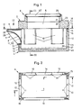
- Fig. 1 einen Längsschnitt durch einen Kabelschacht entlang der Linie I - I in Fig. 2,
- Fig. 2 die Draufsicht auf die Wanne,
- Fig. 3 den Querschnitt längs der Linie 111 - -111 in Fig. 1,
- Fig. 4 die Draufsicht auf einen Mündungstrichter, und
- Fig. 5 bis Fig. 7 eine Variante des Mündungstrichters im Grundriss, in Vorderansicht und im Längsschnitt.
- Der Einstiegs-Kabelschacht wird aus Beton hergestellt und umfasst eine quaderförmige Wanne 4, eine Deckplatte 2, einen Aufsatzrahmen 6 sowie Mündungstrichter 7. Die Wanne 4 hat einen rechteckigen Grundriss. An den beiden Querwänden 2 ist benachbart zur einen, durchgehenden Längswand 13 je eine rechteckige Öffnung 10 vorgesehen, die sich bis zum oberen Rand der Wanne 4 erstreckt. Die andere Längswand 14 weist benachbart zu den Querwänden 2 zwei gleichgeformte Öffnungen 10 auf. Die Öffnungen 10 haben innen seitlich eine stufenförmige Erweiterung 11. Die Wanne 4 kann auch zweistückig ausgebildet werden, wobei auf einen durchgehenden wannenförmigen Unterteil 4b ein mit den Öffnungen 10 versehener rahmenförmiger Oberteil 4a aufgesetzt ist. Durch einen längs des Umfangs verlaufenden Vorsprung 36 des Oberteils 4a und eine entsprechende Ausnehmung 37 im Unterteil 4b sind die beiden Teile zueinander zentriert. Diese Variante ist in den Fig. 1 und 3 durch strichpunktierte Linien angedeutet.
- Mindestens in den beiden Öffnungen 10 der Querwände 12 sind Mündungstrichter 7 eingesetzt. Der Mündungstrichter 7 gemäss Fig. 1 und 4 ist für den Anschluss von Zores-Kabelkanalprofilen vorgesehen. Er besteht aus einem halbschalenförmigen Unterteil 8 und einem halbschalenförmigen Oberteil 9, die zusammen eine trichterförmige Öffnung 29 umschliessen. An der Mündung weist die Öffnung 29 eine Erweiterung 28 zur Aufnahme von Zores-Kabelkanalprofilen auf. Zweckmässig ist diese Erweiterung für die grösste gängige Zores-Grösse ausgelegt. Für den Anschluss kleinerer Zores-Profile wird in die Ausnehmung 28 ein Reduzierstück eingesetzt. Der Unterteil 8 weist längs seines unteren Randes eine Nase 31 zur Anlage an der Aussenfläche der Wanne 4 auf. Seitlich sind sowohl am Unterteil 8, als auch am Oberteil 9 Flansche 30 vorgesehen, die in die Erweiterungen 11 der Öffnungen 10 passen.
- Durch diese Ausbildung des Mündungstrichters 7 ist es möglich, ihn bei aufgesetzter Deckplatte 2 von innen her durch die Öffnungen 10 einzusetzen. Der nachträgliche Einsatz in eine der Öffnungen 10 der Längswand 14 ist deshalb ohne grossen Aufwand bei späteren zusätzlichen Kanalabgängen möglich. Durch Anlage der Nase 31 an der Aussenfläche und des Flansches 30 in der Erweiterung 11 wird der Mündungstrichter sicher gehalten. Durch die zweiteilige Ausbildung des Mündungstrichters und die bis an den Rand der Wanne 4 reichenden Öffnungen ist es möglich, den Kabelschacht in bestehende Kabelanlagen einzusetzen, ohne die Kabel durchtrennen zu müssen.
- Statt des Mündungstrichters 7 für Zores-Profile kann auch ein Rohrblock-Mündungstrichter 7' gemäss Fig. 5 bis 7 in die Öffnungen 10 eingesetzt werden. Dieser Mündungstrichter ist einstückig ausgebildet und weist wiederum eine trichterförmige Öffnung 29', unten die Nase 31 und seitlich die Flansche 30 auf. Am Mündungsende ist eine Endplatte 33 mit mehreren abgestuften Bohrungen 32 zum Einschieben von Kunststoffrohren vorgesehen. Um auch bei dieser Ausführungsform ein Einsetzen des Mündungstrichters 7' bei aufgesetzter Deckplatte 2 zu ermöglichen, kann die Höhe des Mündungstrichters 7' geringer sein als die Höhe der Öffnungen 10. Der bei eingesetztem Mündungstrichter oben entstehende Spalt kann zum Beispiel durch einen Keilstab verschlossen werden.
- Die Deckplatte 2 ist zum Befahren durch Schwerlastverkehr dimensioniert. Sie weist einen rechteckigen Einstiegsöffnung 5 auf und ist auf der Wanne 4 formschlüssig zentriert, damit Seitenkräfte sicher von der Deckplatte 2 auf die Wanne übertragen werden können. Dazu sind längs des oberen Randes der Wanne 4 mehrere konkave Winkelprofile 15 mit angeschweissten Verankerungseisen 16 in die Wanne 4 eingegossen. In die Deckplatte 2 sind entsprechende konvexe Winkelprofile 17 mit Verankerungseisen 18 eingegossen.
- Auf die Deckplatte 2 ist ein rechteckiger Aufsatzrahmen 6 aufgesetzt. Ein umlaufender Vorsprung 21 zentriert den Rahmen 6 durch Eingriff in eine entsprechende Ausnehmung 22 der Deckplatte 2 und sichert ihn gegen seitliche Verschiebung. Am oberen Rand ist in den Aufsatzrahmen 6 ein eiserner Verstärkungsrahmen 25 eingegossen, in welchen zweite Deckelelemente 40 zum Verschliessen der Einstiegsöffnung 5 eingelegt werden. Der Verstärkungsrahmen 25 überragt den Aufsatzrahmen um die Dicke des vorgesehenen Strassen-Endbelages.
- Zur Anpassung an die Quer- und Längsneigung der Strassenoberfläche können Aufsatzrahmen 6 mit entsprechend nicht parallelen Grund- und Deckflächen vorgesehen werden. Die Feinjustierung kann durch Einschlagen von Keilen in die Trennfläche 23 zwischen Aufsatzrahmen 6 und Deckplatte 2 erfolgen, wobei der entstehende Spalt mit Mörtel gefüllt wird.
- In die nicht benötigten Öffnungen 10 in der Längswand 14 sind Blinddeckel 19 von aussen her eingesetzt. Sie liegen mit einer Schulter 20 an der Aussenfläche der Wanne 4 an. Sie sind nach Bedarf wasserdicht abschliessbar.
Claims (9)
Priority Applications (1)
| Application Number | Priority Date | Filing Date | Title |
|---|---|---|---|
| AT85810530T ATE35488T1 (de) | 1984-11-28 | 1985-11-12 | Kabelschacht. |
Applications Claiming Priority (2)
| Application Number | Priority Date | Filing Date | Title |
|---|---|---|---|
| CH5681/84 | 1984-11-28 | ||
| CH568184 | 1984-11-28 |
Publications (2)
| Publication Number | Publication Date |
|---|---|
| EP0184986A1 EP0184986A1 (de) | 1986-06-18 |
| EP0184986B1 true EP0184986B1 (de) | 1988-06-29 |
Family
ID=4297610
Family Applications (1)
| Application Number | Title | Priority Date | Filing Date |
|---|---|---|---|
| EP85810530A Expired EP0184986B1 (de) | 1984-11-28 | 1985-11-12 | Kabelschacht |
Country Status (3)
| Country | Link |
|---|---|
| EP (1) | EP0184986B1 (de) |
| AT (1) | ATE35488T1 (de) |
| DE (1) | DE3563582D1 (de) |
Families Citing this family (1)
| Publication number | Priority date | Publication date | Assignee | Title |
|---|---|---|---|---|
| FR2687024B1 (fr) * | 1992-01-31 | 1994-06-10 | Danis Nathalie | Dispositif destine a apporter ameliorations et securite dans la pose, la fixation et le raccordement de supports devant recevoir une ou plusieurs alimentations electriques. |
Family Cites Families (4)
| Publication number | Priority date | Publication date | Assignee | Title |
|---|---|---|---|---|
| DE446058C (de) * | 1928-05-05 | Edmund Seifert Fa | Kabelbrunnen aus Platten von Eisenbeton oder aehnlichem Baustoff | |
| DE490584C (de) * | 1928-02-15 | 1930-01-30 | Edmund Seifert Fa | Kabelbrunnen aus Platten von Eisenbeton oder aehnlichem Baustoff |
| DE2525285C3 (de) * | 1975-06-06 | 1979-09-27 | Passavant-Werke Michelbacher Huette, 6209 Aarbergen | Kreisrundes Schachtbauteil, insbesondere Ausgleichsring für einen Straßenschacht |
| CH640372A5 (en) * | 1981-01-09 | 1983-12-30 | Beck Rene Sa | Cable chamber |
-
1985
- 1985-11-12 EP EP85810530A patent/EP0184986B1/de not_active Expired
- 1985-11-12 AT AT85810530T patent/ATE35488T1/de active
- 1985-11-12 DE DE8585810530T patent/DE3563582D1/de not_active Expired
Also Published As
| Publication number | Publication date |
|---|---|
| EP0184986A1 (de) | 1986-06-18 |
| ATE35488T1 (de) | 1988-07-15 |
| DE3563582D1 (en) | 1988-08-04 |
Similar Documents
| Publication | Publication Date | Title |
|---|---|---|
| DE2251986C2 (de) | Schalungsbauteil zum Herstellen von mehreren Leitungsdurchführungen in einer Betonwand | |
| EP0225506A1 (de) | Leichtflüssigkeitsabscheider | |
| EP0184986B1 (de) | Kabelschacht | |
| EP1001101B1 (de) | Entwässerungsrinne | |
| DE29605862U1 (de) | Gehäuse eines Elektrizitätszählers | |
| DE19631232C2 (de) | Duschzelle mit Duschplateau | |
| DE8315463U1 (de) | Wasserablaufstein | |
| DE3637063A1 (de) | Abdeckung fuer abflusskanaele | |
| DE69705477T2 (de) | Kabelkanal- und Führungssystem für Flughafenbaken | |
| DE3823664C1 (en) | Separating device for sewage | |
| DE9203276U1 (de) | Schalung | |
| AT387806B (de) | Bausatz fuer eine entwaesserungsrinne | |
| EP0447761B1 (de) | Rechteckige Schachtabdeckung | |
| DE8808937U1 (de) | Abscheidevorrichtung für Abwasser | |
| DE3712340C2 (de) | ||
| DE2900517C2 (de) | Filter mit mehreren Zellen für körnigen Filterstoff | |
| DE20318617U1 (de) | Einlaufgehäuse | |
| DE19508317A1 (de) | Balkontragendes Bauelement | |
| DE2301149C3 (de) | Gehäuse für Transformatorstationen | |
| DE2912131B1 (de) | Garage | |
| DE3347734A1 (de) | Rolladenendstab mit den auslassschlitz im rolladenkasten abdichtender dichtung | |
| DE60214110T2 (de) | Senkgrube mit Verschluss und Verfahren zum Verschliessen | |
| DE9014355U1 (de) | Vorrichtung zum Überbrücken und Abdichten einer Bodendehnungsfuge | |
| DE4415327A1 (de) | Aufsetzbare längsverlaufende Betonfertigrandschalung | |
| DE29702526U1 (de) | Vorichtung zum Befestigen von Pfosten wie Geländer- oder Gerüstpfosten |
Legal Events
| Date | Code | Title | Description |
|---|---|---|---|
| PUAI | Public reference made under article 153(3) epc to a published international application that has entered the european phase |
Free format text: ORIGINAL CODE: 0009012 |
|
| AK | Designated contracting states |
Kind code of ref document: A1 Designated state(s): AT BE CH DE FR GB IT LI LU NL SE |
|
| 17P | Request for examination filed |
Effective date: 19860606 |
|
| 17Q | First examination report despatched |
Effective date: 19870929 |
|
| ITF | It: translation for a ep patent filed | ||
| GRAA | (expected) grant |
Free format text: ORIGINAL CODE: 0009210 |
|
| AK | Designated contracting states |
Kind code of ref document: B1 Designated state(s): AT BE CH DE FR GB IT LI LU NL SE |
|
| REF | Corresponds to: |
Ref document number: 35488 Country of ref document: AT Date of ref document: 19880715 Kind code of ref document: T |
|
| GBT | Gb: translation of ep patent filed (gb section 77(6)(a)/1977) | ||
| REF | Corresponds to: |
Ref document number: 3563582 Country of ref document: DE Date of ref document: 19880804 |
|
| ET | Fr: translation filed | ||
| PLBE | No opposition filed within time limit |
Free format text: ORIGINAL CODE: 0009261 |
|
| STAA | Information on the status of an ep patent application or granted ep patent |
Free format text: STATUS: NO OPPOSITION FILED WITHIN TIME LIMIT |
|
| 26N | No opposition filed | ||
| ITTA | It: last paid annual fee | ||
| EPTA | Lu: last paid annual fee | ||
| EAL | Se: european patent in force in sweden |
Ref document number: 85810530.7 |
|
| PGFP | Annual fee paid to national office [announced via postgrant information from national office to epo] |
Ref country code: NL Payment date: 19990921 Year of fee payment: 15 |
|
| PGFP | Annual fee paid to national office [announced via postgrant information from national office to epo] |
Ref country code: CH Payment date: 19991008 Year of fee payment: 15 |
|
| PGFP | Annual fee paid to national office [announced via postgrant information from national office to epo] |
Ref country code: FR Payment date: 19991011 Year of fee payment: 15 |
|
| PGFP | Annual fee paid to national office [announced via postgrant information from national office to epo] |
Ref country code: AT Payment date: 19991013 Year of fee payment: 15 |
|
| PGFP | Annual fee paid to national office [announced via postgrant information from national office to epo] |
Ref country code: SE Payment date: 19991018 Year of fee payment: 15 |
|
| PGFP | Annual fee paid to national office [announced via postgrant information from national office to epo] |
Ref country code: GB Payment date: 19991020 Year of fee payment: 15 |
|
| PGFP | Annual fee paid to national office [announced via postgrant information from national office to epo] |
Ref country code: DE Payment date: 19991028 Year of fee payment: 15 |
|
| PGFP | Annual fee paid to national office [announced via postgrant information from national office to epo] |
Ref country code: BE Payment date: 19991122 Year of fee payment: 15 |
|
| PGFP | Annual fee paid to national office [announced via postgrant information from national office to epo] |
Ref country code: LU Payment date: 19991126 Year of fee payment: 15 |
|
| PG25 | Lapsed in a contracting state [announced via postgrant information from national office to epo] |
Ref country code: LU Free format text: LAPSE BECAUSE OF NON-PAYMENT OF DUE FEES Effective date: 20001112 Ref country code: GB Free format text: LAPSE BECAUSE OF NON-PAYMENT OF DUE FEES Effective date: 20001112 Ref country code: AT Free format text: LAPSE BECAUSE OF NON-PAYMENT OF DUE FEES Effective date: 20001112 |
|
| PG25 | Lapsed in a contracting state [announced via postgrant information from national office to epo] |
Ref country code: SE Free format text: THE PATENT HAS BEEN ANNULLED BY A DECISION OF A NATIONAL AUTHORITY Effective date: 20001129 |
|
| PG25 | Lapsed in a contracting state [announced via postgrant information from national office to epo] |
Ref country code: LI Free format text: LAPSE BECAUSE OF NON-PAYMENT OF DUE FEES Effective date: 20001130 Ref country code: CH Free format text: LAPSE BECAUSE OF NON-PAYMENT OF DUE FEES Effective date: 20001130 Ref country code: BE Free format text: LAPSE BECAUSE OF NON-PAYMENT OF DUE FEES Effective date: 20001130 |
|
| BERE | Be: lapsed |
Owner name: MARTIN MANNHART HOCH- UND TIEFBAU Effective date: 20001130 |
|
| PG25 | Lapsed in a contracting state [announced via postgrant information from national office to epo] |
Ref country code: NL Free format text: LAPSE BECAUSE OF NON-PAYMENT OF DUE FEES Effective date: 20010601 |
|
| GBPC | Gb: european patent ceased through non-payment of renewal fee |
Effective date: 20001112 |
|
| REG | Reference to a national code |
Ref country code: CH Ref legal event code: PL |
|
| EUG | Se: european patent has lapsed |
Ref document number: 85810530.7 |
|
| PG25 | Lapsed in a contracting state [announced via postgrant information from national office to epo] |
Ref country code: FR Free format text: LAPSE BECAUSE OF NON-PAYMENT OF DUE FEES Effective date: 20010731 |
|
| NLV4 | Nl: lapsed or anulled due to non-payment of the annual fee |
Effective date: 20010601 |
|
| PG25 | Lapsed in a contracting state [announced via postgrant information from national office to epo] |
Ref country code: DE Free format text: LAPSE BECAUSE OF NON-PAYMENT OF DUE FEES Effective date: 20010801 |
|
| REG | Reference to a national code |
Ref country code: FR Ref legal event code: ST |