EP0185189A2 - Antireflex beschichtete, transparente Abdeckung von Zeichen, insbesondere für Anzeigegeräte - Google Patents
Antireflex beschichtete, transparente Abdeckung von Zeichen, insbesondere für Anzeigegeräte Download PDFInfo
- Publication number
- EP0185189A2 EP0185189A2 EP85114236A EP85114236A EP0185189A2 EP 0185189 A2 EP0185189 A2 EP 0185189A2 EP 85114236 A EP85114236 A EP 85114236A EP 85114236 A EP85114236 A EP 85114236A EP 0185189 A2 EP0185189 A2 EP 0185189A2
- Authority
- EP
- European Patent Office
- Prior art keywords
- layer
- coated transparent
- refractive
- transparent cover
- substance
- Prior art date
- Legal status (The legal status is an assumption and is not a legal conclusion. Google has not performed a legal analysis and makes no representation as to the accuracy of the status listed.)
- Withdrawn
Links
Images

Classifications
-
- G—PHYSICS
- G02—OPTICS
- G02B—OPTICAL ELEMENTS, SYSTEMS OR APPARATUS
- G02B5/00—Optical elements other than lenses
- G02B5/20—Filters
- G02B5/28—Interference filters
- G02B5/285—Interference filters comprising deposited thin solid films
-
- G—PHYSICS
- G02—OPTICS
- G02B—OPTICAL ELEMENTS, SYSTEMS OR APPARATUS
- G02B1/00—Optical elements characterised by the material of which they are made; Optical coatings for optical elements
- G02B1/10—Optical coatings produced by application to, or surface treatment of, optical elements
- G02B1/11—Anti-reflection coatings
- G02B1/113—Anti-reflection coatings using inorganic layer materials only
- G02B1/115—Multilayers
Definitions
- the invention relates to an anti-reflective coated transparent cover for characters, in particular for display devices, consisting of a carrier material and an anti-reflective coating.
- Sensitive objects, especially instruments, are covered with transparent panes to prevent dirt and mechanical damage, which often do not allow a perfect reading due to the reflection due to the light.
- the surface of the transparent covers would be matted, for example.
- this roughening can only be used if the characters to be displayed are directly behind the pane, because the sharpness and thus the legibility decrease with the distance of the characters from the cover.
- curved cover disks for example made of polymethylacrylate, are also used. The curvature is designed so that the driver's eye is almost in focus. Due to individual adjustment of the seat, this often does not apply, so that the reading accuracy and thus the safety suffers, particularly in the case of strongly changing light conditions.
- curved cover plates require greater depths, which complicates an often desired compact design.
- the object of the invention is to find a low-reflection, surface-insensitive, closed cover with a shallow depth, which allows sharp-contoured reproduction of the characters and images behind it, even in strongly changing lighting conditions, from a wide range of viewing points.
- the object is achieved according to the invention in that, as an antireflection coating, at least on one side of the carrier material, one layer of a high-index substance with an optical thickness of ⁇ 1 ⁇ 1/8 and one layer of a low-index substance with an optical thickness of /) 1 - 1/8, and a layer of a highly refractive substance having an optical thickness ⁇ 2 ⁇ 1/2 and a layer of a low refractive index material having an optical thickness ⁇ 2 • 1/4 are arranged, is the wavelength ⁇ 1 and ⁇ 2 in Ratio 1: 1.3 to 1: 3, especially 1: 1.5 - 1: 1.9.
- an angle of incidence I 13 + 3 °, that is an angle between the plumb line on the mirror surface and the incident light beam, is selected to optimize the anti-reflective coating. This has the advantage that a satisfactory reflection elimination is achieved even when viewed from the side.
- the cover has only a small overall depth, so that it can still be used even in structurally narrow conditions.
- ⁇ 1 lies in or directly below the short-wave end range and ⁇ 2 in the middle (from 40 to 60%) or long-wave end range of the total spectral range to be taken into account in the anti-reflection treatment.
- the wavelength ⁇ 1 is in the range of 275-450 nm and the wavelength ⁇ 2 is in the range of 500-850 nm.
- antireflection coatings with different wavelengths or wavelength ratios ⁇ 1i / ⁇ 2i or ⁇ 1j / ⁇ 2j are arranged on the opposite sides of the carrier material.
- the anti-reflective coating can be made even more neutral.
- the wavelengths ⁇ 1i and ⁇ 2i or ⁇ 1j and ⁇ 2j can move closer together in order to optimally reflect an especially disturbing, narrow spectral range.
- the high-index dielectric substance consists of TiO 2 and the low-index dielectric substance consists of SiO 2 .
- a polycarbonate film is used as the carrier material.
- This film has great light transmission and high strength.
- Suitable polycarbonates to be stabilized according to the invention are the polycondensates obtainable by reacting diphenols, in particular dihydroxydiarylalkanes, with phosgene or diesters of carbonic acid, and in addition to the unsubstituted dihydroxydiarylalkanes, those whose aryl radicals are in the o- and / or m-position to the hydroxyl group are also suitable Wear methyl groups or halogen atoms.
- Branched polycarbonates are also suitable.
- the polycarbonates to be stabilized have average weight average molecular weights Mw between 10,000 and 100,000, preferably between 20,000 and 40,000, determined by measuring the rel. Viscosity in CH 2 C1 2 at 25 ° C and a concentration of 0.5 g per 100 ml.
- Suitable diphenols are, for example, hydroquinone, resorcinol, 4,4'-dihydroxydiphenyl, bis- (hydroxyphenyl) alkanes such as, for example, C 1 -C 8 -alkylene- or C2-ca-alkylidenebisphenols, bis- (hydroxyphenyl) -cycloalkanes such as C 5 -C 15 cycloalkylene or C 5 -C 15 cycloalkylidene bisphenols, bis (hydroxyphenyl) sulfides, ethers, ketones, sulfoxides or sulfones.
- ⁇ , ⁇ '-bis (hydroxyphenyl) diisopropylbenzene and the corresponding ring-alkylated or ring-halogenated compounds Polycarbonates based on bis- (4-hydroxyphenyl) propane-2.2 (bisphenol A), bis- (4-hydroxy-3,5-dichlorophenyl) propane-2.2 (tetrachlorobisphenol A), bis- (4- hydroxy-3,5-dibromophenyl) propane-2.2 (tetrabromobisphenol A), bis- (4-hydroxy-3,5-dimethylphenyl) propane-2.2 (tetramethylbisphenol A), bis- (4-hydroxy- phenyl) -cyclohexane-1.1 (bisphenol Z) and based on trinuclear bisphenols such as ⁇ , ⁇ '-bis (4-hydroxyphenyl) -p-diisopropylbenzene.
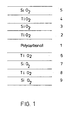
- This anti-reflex system can be with a further A ntireflexsystem on the other side of the foil with layers of TiO supplement 2 16 nm (6), Si0 2 30 nm (7), TiO 2 119 nm (8) and Si0 2 91 nm (9) where maxima of the residual reflection from one side coincide with minima from the other side.
- Curve A shows the reflection on an uncoated film.
- Curve B shows the reflection of a film coated on one side.
- Curve C represents the reflection on a film coated on both sides.
- a 600 ⁇ m thick, clear polycarbonate film is vapor-coated on both sides in accordance with the method according to the invention in such a way that a ⁇ 1 . 1/8 optical layer of TiO 2 , then a ⁇ 1 ⁇ 1/8 optical layer of SiO Z is applied. This is followed by a 1/2 optical layer of TiO 2 and a ⁇ 2 ⁇ 1/4 optical layer of Si0 2 .
- the individual layers are applied, for example, in a strip vapor deposition system with 4 evaporators arranged on either side of the film.
- the film obtained on both sides with an anti-reflective coating is used as a cover for the display instrument of a passenger car, in the housing of which there are four different individual instruments.
- the distance between the film and the hands is 1 cm.
- the film is fixed to the housing in such a way that the outer edge has bores with 3 mm ⁇ which are arranged at a distance of 100 mm.
- the film, which is flush with the outer edge, has corresponding openings in the same place.
- a 10 mm wide frame with a wall thickness of 4 mm is used, which is provided with pins so that they fit into the existing holes in the lower part of the housing.
- a 100 ⁇ m thick polycarbonate film coated on one side in accordance with Example 1 is laminated on a flat sheet of 3 mm thick polymethacrylate in such a way that a UV-curable resin based on acrylate is applied to the sheet of PMMA.
- the film is placed with the uncoated side so that no air is trapped between the film and resin.
- the adhesive is then hardened by irradiation with UV light.
- the self-supporting plate can be cut to the required size and clipped into the housing of a display device.
- Example 3 Corresponding to Example 3, but with the PMMA plate being laminated on both sides with a polycarbonate film coated on one side with an anti-reflective coating.
- a 100 micron thick film made of polycarbonate is coated on one side in accordance with Example 1 in such a way that SiO 2 is used as the low-index substance and Ti0 2 is used as the high-index substance.
- This polycarbonate film coated on one side with an anti-reflective coating is inserted into the mold cavity of an injection molding tool in such a way that the anti-reflective coated side faces the outer wall of the mold.
- the film is covered in a manner known per se with a transparent plastic.
Landscapes
- Physics & Mathematics (AREA)
- General Physics & Mathematics (AREA)
- Optics & Photonics (AREA)
- Chemical & Material Sciences (AREA)
- Inorganic Chemistry (AREA)
- Surface Treatment Of Optical Elements (AREA)
- Laminated Bodies (AREA)
- Organic Low-Molecular-Weight Compounds And Preparation Thereof (AREA)
- Devices For Indicating Variable Information By Combining Individual Elements (AREA)
- Details Of Measuring And Other Instruments (AREA)
- Optical Filters (AREA)
Abstract
Description
- Die Erfindung betrifft eine antireflex beschichtete transparente Abdeckung von Zeichen, insbesondere für Anzeigegeräte, bestehend aus einem Trägermaterial und einem Antireflexbelag.
- Empfindliche Gegenstände, insbesondere Instrumente, werden zur Vermeidung von Verschmutzungen und mechanische Beschädigungen durch transparente Scheiben abgedeckt, die bei bestimmten Lichteinfall infolge der Spiegelung oft eine einwandfreie Ablesung nicht mehr zulassen.
- Um solche störenden Reflexionen zu vermeiden, würde z.B. die Oberfläche der transparenten Abdeckungen mattiert. Diese Aufrauhung ist aber nur dann anwendbar, wenn die anzuzeigenden Zeichen unmittelbar hinter der Scheibe liegen, denn mit dem Abstand der Zeichen von der Abdeckung nimmt die Schärfe und damit die Lesbarkeit ab. Bei Kraftfahrzeug-Anzeigeinstrumenten werden auch gewölbte Abdeckscheiben, beispielsweise aus Polymethylacrylat, verwendet. Die Krümung ist so angelegt, daß das Auge des Fahrers sich annähernd im Brennpunkt befindet. Durch individuelle Einstellung des Sitzes trifft dieses aber oft nicht zu, so daß insbesondere bei stark wechselnden Lichtverhältnissen die Ablesegenauigkeit und damit die Sicherheit leidet. Ferner erfordern gekrümmte Abdeckscheiben größere Bautiefen, was eine oft gewünschte Kompaktbauweise erschwert.
- Aufgabe der Erfindung ist es, eine reflexionsarme, oberflächenunempfindliche, geschlossene Abdeckung mit geringer Bautiefe zu finden, die eine konturenscharfe Wiedergabe der dahinterliegenden Zeichen und Bilder auch bei stark wechselnden Lichtverhältnisse aus einem breiten Spektrum von Betrachtungspunkten erlaubt.
- Die Aufgabe wird erfindungsgemäß dadurch gelöst, daß als Antireflexbelag mindestens auf einer Seite des Trägermaterials nacheinander eine Schicht aus einer hochbrechenden Substanz mit einer optischen Dicke von λ1·1/8 und eine Schicht aus einer niedrigbrechenden Substanz mit einer optischen Dicke von /) 1-1/8, sowie eine Schicht aus einer hochbrechenden Substanz mit einer optischen Dicke λ2·1/2 und eine Schicht aus einer niedrigbrechenden Substanz mit einer optischen Dicke λ2·1/4 angeordnet wird, wobei die Wellenlänge λ1 und λ2 im Verhältnis 1:1,3 bis 1:3, insbesondere 1:1,5 - 1:1,9, stehen.
- Für den Fachmann ist überraschend, daß bei dem Aufbringen der Schichten im Vakuum unter reaktiven, oxidierenden Bedingungen aus z.B. Ti203; Si02 in der obengenannten Reihenfolge, eine weitgehend spiegelfreie, konturenscharfe Sicht auf die Zeichen hinter der transparenten Folie zu erreichen ist.
- Für den Anwendungsfall der Sichtschirmentspiegelung, die sowohl der Kontrastverstärkung als auch der Störreflexbeseitigung dient, wird zur Entspiegelungoptimierung ein Einfallswinkel I = 13 + 3°, das ist ein Winkel zwischen Lot auf Spiegelfläche und einfallendem Lichtstrahl, gewählt. Dies hat den Vorteil, daß auch noch bei seitlicher Aufsicht eine befriedigende Reflexbeseitigung erzielt wird.
- Ein weiterer Vorzug besteht darin, daß die Abdeckung nur eine geringe Bautiefe besitzt, so daß sie auch bei konstruktiv engen Verhältnissen noch eingesetzt werden kann.
- In einer besonderen Ausführungsform liegt λ1 in oder direkt unter dem kurzwelligen Endbereich und λ2 im mittleren (von 40 bis 60 %) bzw. langwelligen Endbereich des bei der Entspiegelung zu berücksichtigenden Gesamtspektralbereiches.
- Gute Ergebnisse werden erzielt, wenn die Wellenlänge λ1 im Bereich von 275-450 nm und die Wellenlänge λ2 im Bereich von 500-850 nm liegt.
- In einer anderen Ausführungsform sind auf den gegenüberliegenden Seiten des Trägermaterials Antireflexbeläge mit unterschiedlichen Wellenlängen bzw. Wellenlängen-Verhältnisse λ1i/λ2i bzw. λ1j/λ2j angeordnet.
- Bei Anordnung von Antireflexbelängen, deren optische Schichtdicken zu beiden Seiten der durchsichtigen Folie unterschiedliche Wellenlängen λ1i und λ2i bzw. λ1j und entsprechen, kann die Entspiegelung noch neutraler gestaltet werden. Gleichzeitig können die Wellenlängen λ1i und λ2i bzw. λ1j und λ2j näher zusammenrücken, um einen besonders störenden, engeren Spektralbereich besonders optimal zu entspiegeln.
- In einer weiteren Ausführungsform besteht die hochbrechende dielektrische Substanz aus TiO2 und die niedrigbrechende dielektrische Substanz aus SiO2.
- Diese Substanzen, die auch durch reaktives Aufdampfen von Ti203 bzw. SiO entstehen können, haben sich bewährt und zeichnen sich durch gute Kratzfestigkeit aus. Denkbar sind aber auch Kombination mit MgF2 und Ta2O5. Bei beidseitiger Entspiegelung können auch unterschiedliche Materialkombinationen an den beiden Seiten des Trägermaterials verwendet werden.
- In einer Ausführungsform wird als Trägermaterial eine Polycarbonat Folie verwendet.
- Diese Folie besitzt eine große Lichtdurchlässigkeit und hohe Festigkeit.
- Als erfindungsgemäß zu stabilisierende Polycarbonate kommen die durch Umsetzung von Diphenolen, insbesondere von Dihydroxydiarylalkanen, mit Phosgen oder Diestern der Kohlensäure erhältlichen Polykondensate in Betracht, wobei außer den unsubstituierten Dihydroxydiarylalkanen auch solche geeignet sind, deren Arylreste in o- und/ oder m-Stellung zur Hydroxylgruppe Methylgruppen oder Halogenatome tragen. Ebenso sind verzweigte Polycarbonate geeignet.
- Die zu stabilisierenden Polycarbonate haben mittlere Gewichtsmittel-Molekulargewichte Mw zwischen 10 000 und 100 000, vorzugsweise zwischen 20 000 und 40 000, ermittelt durch Messungen der rel. Viskosität in CH2C12 bei 25°C und einer Konzentration von 0,5 g pro 100 ml.
- Geeignete Diphenole sind z.B. Hydrochinon, Resorcin, 4,4'-Dihydroxydiphenyl, Bis-(hydroxy-phenyl)alkane wie beispielsweise C1-C8-Alkylen- bzw. C2-ca-Alkylidenbis- phenole, Bis-(hydroxyphenyl)-cycloalkane wie beispielsweise C5-C15-Cycloalkylen- bzw. C5-C15-Cycloalkyliden- bisphenole, Bis-(hydroxy-phenyl)-sulfide, -ether, -ketone, -sulfoxide oder -sulfone. Ferner α, α'-Bis-(hydroxyphenyl)-diisopropylbenzol sowie die entsprechenden kernalkylierten bzw. kernhalogenierten Verbindungen. Bevorzugt sind Polycarbonate auf Basis Bis-(4-hydroxy-phenyl)-propan-2.2 (Bisphenol A), Bis-(4-hydroxy-3,5-dichlorphenyl)-propan-2.2 (Tetrachlorbisphenol A), Bis-(4-hy- droxy-3,5-dibromphenyl)-propan-2.2 (Tetrabrombisphenol A), Bis-(4-hydroxy-3,5-dimethyl-phenyl)-propan-2.2 (Tetramethylbisphenol A), Bis-(4-hydroxy-phenyl)-cyclohexan-1.1 (Bisphenol Z) sowie auf Basis von Dreikernbisphenolen wie α,α'-Bis-(4-hydroxyphenyl)-p-diisopropylbenzol.
- Ein Beispiel der Erfindung ist in den Zeichnungen dargestellt und wird nachstehend näher erläutert
- Fig. 1 Schichtaufbau
- Fig. 2 Diagramm
- In Fig. 1 ist eine Trägerfolie 1 aus Polycarbonat dargestellt auf die durch Bedampfen nacheinander folgende Schichten mit mechanischen Dicken TiO214 nm (2), Si0225 nm (3), TiO2 134 nm (4) und SiO2105 nm (5) aufgetragen sind, wobei als Wellenlängen λ1 = 315 nm und λ2 = 613 nm bzw. als Verhältnis λ1/λ2 = 1,9 gewählt wurden.
- Dieses Antireflexsystem läßt sich mit einem weiteren Antireflexsystem auf der anderen Seite der Folie mit Schichten TiO216 nm (6), Si0230 nm (7), TiO2119 nm (8) und Si0291 nm (9) ergänzen, wobei Maxima der Restreflexion von der einen Seite mit Minima von der anderen Seite zusammenfallen.
- Eine im langwellig-sichtbaren und nahinfraroten Bereich gelegene Entspiegelung ergibt sich mit TiO2 22 nm, Si02 37 nm, TiO2 161 nm und Si02 121 nm mit Wellenlängen λ1 = 435 nm und λ2 = 710 nm.
- In Fig. 2 ist ein Diagramm dargestellt bei dem auf der Abzisse die Wellenlänge λ und auf der Ordinate der Reflexionsgrad R angegeben ist. Die Kurve A zeigt die Reflexion an einer unbeschichteten Folie. Die Kurve B gibt die Reflexion einer einseitig beschichteten Folie wieder. Die Kurve C stellt die Reflexion an einer beidseitig beschichteten Folie dar. Als Ergebnis kann vermerkt werden, daß die Reflexion im sichtbaren Bereich bis zu einer Wellenlänge von 390 nm wesentlich reduziert wird.
- Eine 600 um dicke glasklare Folie aus Polycarbonat wird nach dem erfindungsgemäßen Verfahren beidseitig so bedampft, daß zuerst eine λ1. 1/8 optische Schicht von TiO2, dann eine λ1· 1/8 optische Schicht von SiOZ aufgebracht wird. Im Anschluß daran folgt eine 1/2 optische Schicht von TiO2 und eine λ2· 1/4 optische Schicht von Si02.
- Die Aufbringung der einzelnen Schichten erfolgt zum Beispiel in einer Bandbedampfungsanläge mit je 4 zu beiden Seiten der Folie angeordneten Verdampfern.
- Die so erhaltene beidseitig antireflektiv beschichtete Folie wird als Abdeckung für das Anzeigeinstrument eines Personenkraftwagens, in dessen Gehäuse sich vier verschiedene Einzelinstrumente befinden, verwendet. Der Abstand zwischen Folie und den Zeigern beträgt 1 cm. Die Fixierung der Folie mit dem Gehäuse geschieht in der Weise, daß der äußere Rand Bohrungen mit 3 mm φ die im Abstand von 100 mm angebracht sind, aufweist. Die Folie, die bündig mit dem äußeren Rand abschließt, hat an der gleichen Stelle entsprechende Durchbrüche. Als Abschluß wird ein 10 mm breiter Rahmen mit einer Wanddicke von 4 mm verwendet, der so mit Stiften versehen ist, daß diese in die vorhandenen Bohrungen des Gehäuseunterteils passen. Durch Vernieten des Abdeckrahmens mit dem Gehäuseunterteil ist die antireflektivbeschichtete Folie zwischen Gehäuse und Abdeckrahmen eingeklemmt. Dieses Anzeigeinstrument hat im Vergleich zu der bisherigen Abdeckung mit der gekrümmten Scheibe eine um 100 mm reduzierte Bautiefe.
- Abdeckung eines Kombiinstrumentes eine PKW's entsprechend Beispiel 1, wobei die Folie mit dem Gehäuseunterteil durch Verkleben mit einem Epoxidharz verbunden wird.
- Auf eine plane Platte aus Polymethacrylat der Dicke 3 mm wird eine einseitig gemäß Beispiel 1 antireflektiv beschichtete 100 µm dicke Folie aus Polycarbonat so aufkaschiert, daß auf die Platte aus PMMA ein UV-härtbares Harz auf Acrylatbasis aufgebracht wird. Die Folie wird mit der nicht beschichteten Seite so aufgelegt, daß keine Luft zwischen Folie und Harz eingeschlossen wird. Anschließend wird der Kleber durch Bestrahlung mit UV-Licht angehärtet. Die selbsttragende Platte kann auf das erforderliche Maß zugeschnitten und in das Gehäuse eines Anzeigegerätes eingeklipst werden.
- Entsprechend Beispiel 3, jedoch daß die Platte aus PMMA beidseitig mit einer einseitig antireflektiv beschichteten Folie aus Polycarbonat kaschiert wird.
- Eine 100 µm dicke Folie aus Polycarbonat wird gemäß Beispiel 1 einseitig so beschichtet, daß als niedrigbrechende Substanz SiO2, und als hochbrechende Substanz Ti02 verwendet wird.
- Diese einseitig antireflektiv beschichtete Folie aus Polycarbonat wird in die Formhöhlung eines Spritzgußwerkzeuges so eingelegt, daß die antireflektiv beschichtete Seite zur Formaußenwand zeigt. Die Folie wird in an sich bekannter Weise mit einem transparenten Kunststoff s. B. Polycarbonat hinterspritzt.
Claims (5)
Applications Claiming Priority (2)
| Application Number | Priority Date | Filing Date | Title |
|---|---|---|---|
| DE19843441948 DE3441948A1 (de) | 1984-11-16 | 1984-11-16 | Antireflex beschichtete, transparente abdeckung von zeichen, insbesondere fuer anzeigegeraete |
| DE3441948 | 1984-11-16 |
Publications (2)
| Publication Number | Publication Date |
|---|---|
| EP0185189A2 true EP0185189A2 (de) | 1986-06-25 |
| EP0185189A3 EP0185189A3 (de) | 1988-07-27 |
Family
ID=6250485
Family Applications (1)
| Application Number | Title | Priority Date | Filing Date |
|---|---|---|---|
| EP85114236A Withdrawn EP0185189A3 (de) | 1984-11-16 | 1985-11-08 | Antireflex beschichtete, transparente Abdeckung von Zeichen, insbesondere für Anzeigegeräte |
Country Status (4)
| Country | Link |
|---|---|
| US (1) | US4725109A (de) |
| EP (1) | EP0185189A3 (de) |
| JP (1) | JPS61137840A (de) |
| DE (1) | DE3441948A1 (de) |
Cited By (4)
| Publication number | Priority date | Publication date | Assignee | Title |
|---|---|---|---|---|
| EP0263541A3 (en) * | 1986-09-05 | 1989-11-02 | N.V. Philips' Gloeilampenfabrieken | A method of manufacturing a display device and a display device made by the method |
| EP0502790A1 (de) * | 1991-03-06 | 1992-09-09 | L'air Liquide, Societe Anonyme Pour L'etude Et L'exploitation Des Procedes Georges Claude | Mehrlagiger Überzug für ein Polycarbonatsubstrat |
| EP0445686A3 (en) * | 1990-03-09 | 1992-09-30 | Kabushiki Kaisha Toshiba | Display device |
| WO1997048992A1 (en) * | 1996-06-17 | 1997-12-24 | Yazaki Corporation | Plastic articles having multi-layer antireflection coatings, and sol-gel process for depositing such coatings |
Families Citing this family (17)
| Publication number | Priority date | Publication date | Assignee | Title |
|---|---|---|---|---|
| JP2590136B2 (ja) * | 1987-09-22 | 1997-03-12 | 日本板硝子株式会社 | 導電性反射防止膜の付着透明板 |
| WO1989008278A1 (fr) * | 1988-02-26 | 1989-09-08 | Fujitsu Limited | Dispositif isolant polarisant et isolateur optique l'utilisant |
| US5483378A (en) * | 1988-04-19 | 1996-01-09 | Litton Systems, Inc. | Fault tolerant anti-reflective coatings |
| US5764416A (en) * | 1988-04-19 | 1998-06-09 | Litton Systems, Inc. | Fault tolerant antireflective coatings |
| US4966437A (en) * | 1988-04-19 | 1990-10-30 | Litton Systems, Inc. | Fault-tolerant anti-reflective coatings |
| US5225821A (en) * | 1988-12-22 | 1993-07-06 | Seiko Epson Corporation | Method for driving an active matrix display and active matrix display |
| US5348805A (en) * | 1990-07-05 | 1994-09-20 | Saint-Gobain Vitrage International | Formation of a layer of aluminum and tin or titanium oxides on a glass substrate |
| US5852513A (en) * | 1997-05-14 | 1998-12-22 | Optical Coating Laboratory, Inc. | Television filter |
| US6266193B1 (en) | 1997-07-24 | 2001-07-24 | Cpfilms Inc. | Anti-reflective composite |
| US6583935B1 (en) | 1998-05-28 | 2003-06-24 | Cpfilms Inc. | Low reflection, high transmission, touch-panel membrane |
| DE10139305A1 (de) * | 2001-08-07 | 2003-03-06 | Schott Glas | Verbundmaterial aus einem Substratmaterial und einem Barriereschichtmaterial |
| US20060139757A1 (en) * | 2004-12-29 | 2006-06-29 | Harris Michael D | Anti-reflective coating for optical windows and elements |
| US8619365B2 (en) * | 2004-12-29 | 2013-12-31 | Corning Incorporated | Anti-reflective coating for optical windows and elements |
| EP2785774A1 (de) * | 2011-12-02 | 2014-10-08 | SABIC Innovative Plastics IP B.V. | Beschichtete polymerfolien |
| CN104903756A (zh) * | 2012-09-28 | 2015-09-09 | 株式会社尼康依视路 | 光学元件及其制造方法 |
| JP2017110979A (ja) * | 2015-12-15 | 2017-06-22 | 株式会社ミツトヨ | 測定器 |
| CN105785491A (zh) * | 2016-05-23 | 2016-07-20 | 浙江水晶光电科技股份有限公司 | 反射滤光片及车载平视显示系统 |
Family Cites Families (5)
| Publication number | Priority date | Publication date | Assignee | Title |
|---|---|---|---|---|
| DE2738044C2 (de) * | 1976-09-27 | 1984-11-29 | AO Inc., Southbridge, Mass. | Linse aus einem synthetischen Polymerisat |
| US4265991A (en) * | 1977-12-22 | 1981-05-05 | Canon Kabushiki Kaisha | Electrophotographic photosensitive member and process for production thereof |
| DE2829279A1 (de) * | 1978-07-04 | 1980-01-17 | Rollei Werke Franke Heidecke | Reflexionsvermindernder mehrschichtenbelag (antireflexbelag) fuer durchsichtige mittelhochbrechende unterlagen |
| JPS57195207A (en) * | 1981-05-26 | 1982-11-30 | Olympus Optical Co Ltd | Light absorbing film |
| JPH116003A (ja) * | 1997-06-16 | 1999-01-12 | Sutoudeio Sanae:Kk | 宝飾品の造形方法及び該方法に使用する母型 |
-
1984
- 1984-11-16 DE DE19843441948 patent/DE3441948A1/de not_active Withdrawn
-
1985
- 1985-11-07 US US06/795,864 patent/US4725109A/en not_active Expired - Fee Related
- 1985-11-08 EP EP85114236A patent/EP0185189A3/de not_active Withdrawn
- 1985-11-15 JP JP60255156A patent/JPS61137840A/ja active Pending
Cited By (7)
| Publication number | Priority date | Publication date | Assignee | Title |
|---|---|---|---|---|
| EP0263541A3 (en) * | 1986-09-05 | 1989-11-02 | N.V. Philips' Gloeilampenfabrieken | A method of manufacturing a display device and a display device made by the method |
| EP0445686A3 (en) * | 1990-03-09 | 1992-09-30 | Kabushiki Kaisha Toshiba | Display device |
| EP0502790A1 (de) * | 1991-03-06 | 1992-09-09 | L'air Liquide, Societe Anonyme Pour L'etude Et L'exploitation Des Procedes Georges Claude | Mehrlagiger Überzug für ein Polycarbonatsubstrat |
| FR2673633A1 (fr) * | 1991-03-06 | 1992-09-11 | Air Liquide | Revetement multicouche pour substrat polycarbonate. |
| US5242740A (en) * | 1991-03-06 | 1993-09-07 | L'air Liquide, Societe Anonyme Pour L'etude Et L'exploitation Des Procedes Georges Claude | Multilayer coating for polycarbonate substrate |
| WO1997048992A1 (en) * | 1996-06-17 | 1997-12-24 | Yazaki Corporation | Plastic articles having multi-layer antireflection coatings, and sol-gel process for depositing such coatings |
| AU725068B2 (en) * | 1996-06-17 | 2000-10-05 | Yazaki Corporation | Plastic articles having multi-layer antireflection coatings, and sol-gel process for depositing such coatings |
Also Published As
| Publication number | Publication date |
|---|---|
| US4725109A (en) | 1988-02-16 |
| EP0185189A3 (de) | 1988-07-27 |
| DE3441948A1 (de) | 1986-05-28 |
| JPS61137840A (ja) | 1986-06-25 |
Similar Documents
| Publication | Publication Date | Title |
|---|---|---|
| EP0185189A2 (de) | Antireflex beschichtete, transparente Abdeckung von Zeichen, insbesondere für Anzeigegeräte | |
| EP3994506B1 (de) | Projektionsanordnung für ein head-up-display (hud) mit p-polarisierter strahlung | |
| EP2909040B1 (de) | Optisch variables flächenmuster | |
| DE3587571T2 (de) | Ophthalmische glas-/kunststoffbeschichtete Linse mit photochromen Eigenschaften. | |
| DE69509670T2 (de) | Retroreflektive geneigte prismenstruktur | |
| DE2915847C2 (de) | Elektrooptisch aktivierbare Anzeige | |
| DE69907405T2 (de) | Optischer mehrkomponentenkörper | |
| DE3731501C2 (de) | Vielschichtiger rückseitig reflektierender Rückspiegel | |
| DE112011100943B4 (de) | Head-up-Display-Vorrichtung | |
| EP1998194A2 (de) | Optisches Schutzfilter und Verfahren zu dessen Herstellung | |
| EP0533074A1 (de) | Optischer Wellenleiter mit einem im wesentlichen planaren Substrat und Verfahren zu dessen Herstellung | |
| DE3528718A1 (de) | Lichtstreueinrichtung | |
| EP0140096B1 (de) | Reflexionsvermindernder Belag für ein optisches Element aus organischem Material | |
| EP0619504A1 (de) | Antireflex-Belag | |
| DE102019112889B4 (de) | Fahrzeugscheibe mit Lichtleiterfolie | |
| DE102017206364A1 (de) | Anordnung zur Reflexionsunterdrückung bei einer Frontscheibenanzeigeeinrichtung sowie Frontscheibenanzeigeeinrichtung | |
| EP4058850B1 (de) | Verfahren zum herstellen einer gebogenen substratscheibe mit einem hologramm, resultierende substratscheibe mit hologramm und ein diese enthaltender scheibenverbund, insbesondere fahrzeugscheibe | |
| DE60206291T2 (de) | Verfahren zur Herstellung von einer Brillenlinse oder Maskelinse mit wenigstens einem Einsatz | |
| WO2021245031A1 (de) | Verbundscheibe mit hologrammelement | |
| DE3024104C2 (de) | Verfahren zur Herstellung einer integrierten mikrooptischen Vorrichtung zur Verwendung mit Multimode-Lichtfasern | |
| DE102022104676A1 (de) | Wellenleiter zum Anzeigen eines Bildes sowie holographische Anzeige mit einem solchen Wellenleiter | |
| DE102017206365A1 (de) | Anordnung zur Reflexionsunterdrückung bei einer Frontscheiben-Anzeigeeinrichtung sowie eine Frontscheiben-Anzeigeeinrichtung | |
| WO2024199990A1 (de) | Anordnung zur erzeugung einer optischen anzeige | |
| WO2024104750A1 (de) | Optisches element, optisches system und fahrzeugscheibe und/oder scheibenlaminat | |
| DE102019114989A1 (de) | Verfahren zur Herstellung eines Verbundglases |
Legal Events
| Date | Code | Title | Description |
|---|---|---|---|
| PUAI | Public reference made under article 153(3) epc to a published international application that has entered the european phase |
Free format text: ORIGINAL CODE: 0009012 |
|
| 17P | Request for examination filed |
Effective date: 19851108 |
|
| AK | Designated contracting states |
Kind code of ref document: A2 Designated state(s): DE FR GB IT |
|
| PUAL | Search report despatched |
Free format text: ORIGINAL CODE: 0009013 |
|
| AK | Designated contracting states |
Kind code of ref document: A3 Designated state(s): DE FR GB IT |
|
| STAA | Information on the status of an ep patent application or granted ep patent |
Free format text: STATUS: THE APPLICATION HAS BEEN WITHDRAWN |
|
| 17Q | First examination report despatched |
Effective date: 19900806 |
|
| 18W | Application withdrawn |
Withdrawal date: 19900808 |
|
| R18W | Application withdrawn (corrected) |
Effective date: 19900808 |
|
| RIN1 | Information on inventor provided before grant (corrected) |
Inventor name: WANK, JOACHIM, DIPL.-ING. Inventor name: HELL, AUGUST, DR. |