EP0185212A1 - Regelung eines Umformers zum Antrieb eines Synchronmotors - Google Patents
Regelung eines Umformers zum Antrieb eines Synchronmotors Download PDFInfo
- Publication number
- EP0185212A1 EP0185212A1 EP19850114725 EP85114725A EP0185212A1 EP 0185212 A1 EP0185212 A1 EP 0185212A1 EP 19850114725 EP19850114725 EP 19850114725 EP 85114725 A EP85114725 A EP 85114725A EP 0185212 A1 EP0185212 A1 EP 0185212A1
- Authority
- EP
- European Patent Office
- Prior art keywords
- speed
- detected
- current
- predetermined threshold
- inverter
- Prior art date
- Legal status (The legal status is an assumption and is not a legal conclusion. Google has not performed a legal analysis and makes no representation as to the accuracy of the status listed.)
- Granted
Links
Images

Classifications
-
- H—ELECTRICITY
- H02—GENERATION; CONVERSION OR DISTRIBUTION OF ELECTRIC POWER
- H02P—CONTROL OR REGULATION OF ELECTRIC MOTORS, ELECTRIC GENERATORS OR DYNAMO-ELECTRIC CONVERTERS; CONTROLLING TRANSFORMERS, REACTORS OR CHOKE COILS
- H02P25/00—Arrangements or methods for the control of AC motors characterised by the kind of AC motor or by structural details
- H02P25/02—Arrangements or methods for the control of AC motors characterised by the kind of AC motor or by structural details characterised by the kind of motor
- H02P25/022—Synchronous motors
- H02P25/03—Synchronous motors with brushless excitation
-
- H—ELECTRICITY
- H02—GENERATION; CONVERSION OR DISTRIBUTION OF ELECTRIC POWER
- H02P—CONTROL OR REGULATION OF ELECTRIC MOTORS, ELECTRIC GENERATORS OR DYNAMO-ELECTRIC CONVERTERS; CONTROLLING TRANSFORMERS, REACTORS OR CHOKE COILS
- H02P2207/00—Indexing scheme relating to controlling arrangements characterised by the type of motor
- H02P2207/05—Synchronous machines, e.g. with permanent magnets or DC excitation
-
- Y—GENERAL TAGGING OF NEW TECHNOLOGICAL DEVELOPMENTS; GENERAL TAGGING OF CROSS-SECTIONAL TECHNOLOGIES SPANNING OVER SEVERAL SECTIONS OF THE IPC; TECHNICAL SUBJECTS COVERED BY FORMER USPC CROSS-REFERENCE ART COLLECTIONS [XRACs] AND DIGESTS
- Y10—TECHNICAL SUBJECTS COVERED BY FORMER USPC
- Y10S—TECHNICAL SUBJECTS COVERED BY FORMER USPC CROSS-REFERENCE ART COLLECTIONS [XRACs] AND DIGESTS
- Y10S388/00—Electricity: motor control systems
- Y10S388/90—Specific system operational feature
- Y10S388/906—Proportional-integral system
Definitions
- the back electromotive force is utilized for commutation. But, while the motor speed is low, the back electromotive force is not sufficiently high for the commutation. Accordingly, the commutation is effected by intermission of the current supplied to the inverter. For switching between the intermission commutation and load commutation, as well as phase control of the thyristors, a control system is employed.
- a conventional control system has a disadvantage in that the torque of the synchronous motor varies sharply or rapidly when there occurs a switching from the intermission commutation to the load commutation. This rapid variation in the torque may cause vibration of the mechanical system, which in turn reduces the life time of the machine.
- An object of the invention is to avoid rapid change in the torque at the time of transition from the intermission commutation to the load commutation.
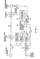
- a control system for a power converter driving a synchronous motor comprising a controllable rectifier converting an AC power into a D C power and an inverter of a load commutation type converting the DC power into an AC power of a variable frequency which is supplied to the synchronous motor, the control system comprising:
- a speed target setter 16 produces a speed target, which is adjustable.
- the speed target represents value to which the motor speed should be varied. For instance, when the motor is started and it is desired to increase the motor speed to the rated speed, the speed target is changed stepwise from zero to the rated speed.
- a variation rate limiter 24 receives the speed target and limits the variation rate to produce a speed reference varied to follow the speed target but within the limited rate. For instance, when the target value is changed stepwise, the speed reference is changed gradually at the limited rate until it reaches the new target value.
- variation rate limiter 24 comprises a comparator 24a comparing the speed target ⁇ t and the speed reference ⁇ r and poducing a signal of a certain level when the former is greater than the latter, a variable resister 24b adjusted to vary the limit rate, an operational amplifier 24c with a capacitor 24d forming an integrator, another comparator 24e comparing the speed reference ⁇ r and the detected speed ⁇ m and prorducing a signal of a certain level if the former is greater than the latter, a switch 24f and a current limiting resistor 24g of a low resistance.
- the comparator 24e is at the above-mentiponed "certain level" and if the switch 24f is closed, the capacitor 24d is rapidly discharged until the reference ⁇ r becomes equal to W m .
- a position detector 17 detects the rotational position of the magnetic field of the synchronous motor 15.
- An example of the position detector produces a set of three-phase logic signals, shown in Fig. 3, 120° apart from each other, the combination of which, a three-bit signal, varies every 60°.
- a speed detector 17A receives the signals from the position detector 17 and determines the speed of the motor 15. The determination of the speed can be made for example by measuring the frequency at which the three-bit signal varies in value.
- a speed controller 18 receives the speed reference W r and the detected speed ⁇ m, from the speed detector 17A and produces a current reference I *.
- FIG. 4 An example of the speed controller 18 is shown in Fig. 4. As illustrated, it comprises an adder 18a determining the difference between the speed reference ⁇ r and the detected speed ⁇ m, an operational amplifier 18b with a first order lag element comprising a series connection of a capacitor 18c and a resistor 18d, and a switch 18e connected across the capapcitor 18c.
- a phase angle controller 22 receives the position- indicating three-bit signal from the position detector 17 and controls the firing angle of the thyristors of the. inverter 14. The phase angle controller 22 also supplies a signal used for intermission commutation in a current controller 19, to be described later.
- An intermission command circuit 23 receives the detected speed ⁇ m from the speed detector .17A and produces intermission signal used for intermission of the current of the rectifier when the detected speed is below a predetermined threshold, which may be set for example at 10% or less of the rated speed.
- a current detector 20 detects the current of the rectifier 12.
- the current controller 19 operates in either of a first and a second modes.
- the current controller 19 is responsive to the curreent reference I * from the speed controller 18 and the detected current I from the current detector 20 and determines a phase reference 0 * , and continuously produces this phase reference ⁇ *.
- the current controller 19 determines the phase reference ⁇ * in a similar manner but intermittently produces this phase reference 0 * .
- a phase angle controller 21 is responsive to the phase reference 0 * for controlling the firing angle of the arms of the rectifier 12 thereby to adjust the DC power outputted from the rectifier 12,
- the rectifier 12 is intermittently made conductive. That is, while the phase reference 0 * is interrupted, the rectifier 12 is kept non-conductive.
- FIG. 5 An example of the current controller 19 is shown in Fig. 5. As illustrated, it comprises an adder 19a determining the difference between the current reference I * and the detected current I, an operational amplifier 19b, and a selector 19c.
- the selector 19c normally selects the output of the amplifier 19b. When the phase reference ⁇ * is to be intermitted, the selector 19c is made to select alternately the output of the amplifier 19b and a preset value for making the phase reference e * zero.
- the operation of the switch 19c is controlled by an intermittent signal from the intermission command circuit 23.
- Increase in the current of the rectifier 12 generally tends to increase the torque and hence the speed of the motor 15.
- Decrease in the current of the rectifier 12 generally tends to decrease the torque and hence of the speed of the motor 15.
- phase angle controller 22 controls the firing phase angle for loadcommutation.
- the current of the rectifier 12 is made to be zero every time the inverter 14 is to be commutated.
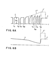
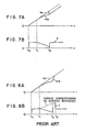
- the motor speed is made to increase rapidly to catch up with the speed reference as shown in Fig. 8A so that there occurs a rapid change in the torque as shown in Fig. 8B. This may cause mechanical vibration of the mechanical system, the coupling and the like. The life time of the mechanical system may therefore be reduced.
- the speed reference ⁇ r is set at the detected actual speed ⁇ m at the time of the switching. But if the actual speed at the time of switching is known, i.e., it is the predetermined threshold, then the arrangement may alternatively be such that the speed reference is set at the known value, e.g., the predetermined threshold.
Landscapes
- Engineering & Computer Science (AREA)
- Power Engineering (AREA)
- Control Of Ac Motors In General (AREA)
- Motor And Converter Starters (AREA)
- Control Of Motors That Do Not Use Commutators (AREA)
Applications Claiming Priority (2)
| Application Number | Priority Date | Filing Date | Title |
|---|---|---|---|
| JP250106/84 | 1984-11-27 | ||
| JP59250106A JPH0612954B2 (ja) | 1984-11-27 | 1984-11-27 | 同期電動機の制御方法 |
Publications (2)
| Publication Number | Publication Date |
|---|---|
| EP0185212A1 true EP0185212A1 (de) | 1986-06-25 |
| EP0185212B1 EP0185212B1 (de) | 1988-11-09 |
Family
ID=17202904
Family Applications (1)
| Application Number | Title | Priority Date | Filing Date |
|---|---|---|---|
| EP85114725A Expired EP0185212B1 (de) | 1984-11-27 | 1985-11-19 | Regelung eines Umformers zum Antrieb eines Synchronmotors |
Country Status (6)
| Country | Link |
|---|---|
| US (1) | US4682094A (de) |
| EP (1) | EP0185212B1 (de) |
| JP (1) | JPH0612954B2 (de) |
| KR (1) | KR900007695B1 (de) |
| CA (1) | CA1259654A (de) |
| DE (1) | DE3566204D1 (de) |
Cited By (2)
| Publication number | Priority date | Publication date | Assignee | Title |
|---|---|---|---|---|
| EP0279428B1 (de) * | 1987-02-17 | 1993-12-29 | Kabushiki Kaisha Toshiba | Regelsystem für einen elektrischen Motor |
| ES2157782A1 (es) * | 1999-04-26 | 2001-08-16 | Jesus Maria Aguirre S A | Dispositivo perfeccionado de sincronismo en generacion de energia electrica. |
Families Citing this family (14)
| Publication number | Priority date | Publication date | Assignee | Title |
|---|---|---|---|---|
| US5281094A (en) * | 1991-05-13 | 1994-01-25 | Alliedsignal Inc | Electromechanical apparatus for varying blade of variable-pitch fan blades |
| US5315225A (en) * | 1991-09-30 | 1994-05-24 | Electric Power Research Institute | Converter for synchronous motor starting |
| EP0661453B1 (de) * | 1993-12-28 | 2003-04-23 | Sanyo Electric Co. Ltd | Klimaanlage und zugehöriger Schaltkreis für den Inverter |
| US6320339B1 (en) * | 2000-09-12 | 2001-11-20 | Universal Scientific Industrial Co., Ltd. | Control device for controlling current passing through a motor |
| US7310287B2 (en) | 2003-05-30 | 2007-12-18 | Fairfield Industries Incorporated | Method and apparatus for seismic data acquisition |
| US7561493B2 (en) * | 2003-05-30 | 2009-07-14 | Fairfield Industries, Inc. | Method and apparatus for land based seismic data acquisition |
| GB0415511D0 (en) * | 2004-07-10 | 2004-08-11 | Trw Ltd | Motor drive voltage-boost control |
| KR101397888B1 (ko) * | 2012-11-19 | 2014-05-20 | 삼성전기주식회사 | 모터 구동 제어 장치, 모터 구동 제어 방법 및 그를 이용한 모터 |
| CA2907864A1 (en) * | 2013-03-27 | 2014-10-02 | Flexenclosure Ab (Publ) | Power supply apparatus with controllable multiple input rectification |
| US10951144B2 (en) | 2017-06-21 | 2021-03-16 | Toshiba Mitsubishi-Electric Industrial Systems Corporation | Thyristor starter |
| EP3644493B1 (de) * | 2017-06-21 | 2023-04-26 | Toshiba Mitsubishi-Electric Industrial Systems Corporation | Thyristorstartvorrichtung |
| WO2018235190A1 (ja) * | 2017-06-21 | 2018-12-27 | 東芝三菱電機産業システム株式会社 | サイリスタ起動装置 |
| US11233466B2 (en) * | 2017-06-21 | 2022-01-25 | Toshiba Mitsubishi-Electric Industrial Systems Corporation | Thyristor starter |
| US11277087B2 (en) * | 2019-01-04 | 2022-03-15 | Toshiba Mitsubishi-Electric Industrial Systems Corporation | Thyristor starter |
Citations (3)
| Publication number | Priority date | Publication date | Assignee | Title |
|---|---|---|---|---|
| DE2711497B2 (de) * | 1976-03-17 | 1979-06-13 | Hitachi, Ltd., Tokio | Anordnung zur Regelung der Drehzahl |
| US4246528A (en) * | 1978-02-27 | 1981-01-20 | Tokyo Shibaura Denki Kabushiki Kaisha | System for controlling alternating current motors |
| EP0107351A2 (de) * | 1982-09-25 | 1984-05-02 | Kabushiki Kaisha Toshiba | Synchronmotor-Steuerung |
Family Cites Families (7)
| Publication number | Priority date | Publication date | Assignee | Title |
|---|---|---|---|---|
| US3372323A (en) * | 1965-03-31 | 1968-03-05 | Reliance Electric & Eng Co | Induction motor slip frequency control system |
| JPS492928B1 (de) * | 1969-11-25 | 1974-01-23 | ||
| US3769564A (en) * | 1972-08-30 | 1973-10-30 | Allis Louis Co | Method and means for limiting the maximum horsepower output of a self-excited alternating current motor |
| JPS5034723A (de) * | 1973-08-02 | 1975-04-03 | ||
| DE2829752A1 (de) * | 1978-07-06 | 1980-01-17 | Siemens Ag | Verfahren zum synchronisieren von synchronmotoren |
| DE3203911A1 (de) * | 1982-02-05 | 1983-08-11 | Siemens AG, 1000 Berlin und 8000 München | Verfahren zur erhoehung der maximaldrehzahl einer synchronmaschine bei vorgegebener erregerfeldstaerke und klemmspannung und schaltungsanordnung zur durchfuehrung des verfahrens |
| US4443747A (en) * | 1982-04-01 | 1984-04-17 | General Electric Company | Transitioning between multiple modes of inverter control in a load commutated inverter motor drive |
-
1984
- 1984-11-27 JP JP59250106A patent/JPH0612954B2/ja not_active Expired - Lifetime
-
1985
- 1985-11-19 EP EP85114725A patent/EP0185212B1/de not_active Expired
- 1985-11-19 DE DE8585114725T patent/DE3566204D1/de not_active Expired
- 1985-11-22 US US06/800,769 patent/US4682094A/en not_active Expired - Lifetime
- 1985-11-26 CA CA000496210A patent/CA1259654A/en not_active Expired
- 1985-11-26 KR KR1019850008832A patent/KR900007695B1/ko not_active Expired
Patent Citations (3)
| Publication number | Priority date | Publication date | Assignee | Title |
|---|---|---|---|---|
| DE2711497B2 (de) * | 1976-03-17 | 1979-06-13 | Hitachi, Ltd., Tokio | Anordnung zur Regelung der Drehzahl |
| US4246528A (en) * | 1978-02-27 | 1981-01-20 | Tokyo Shibaura Denki Kabushiki Kaisha | System for controlling alternating current motors |
| EP0107351A2 (de) * | 1982-09-25 | 1984-05-02 | Kabushiki Kaisha Toshiba | Synchronmotor-Steuerung |
Cited By (2)
| Publication number | Priority date | Publication date | Assignee | Title |
|---|---|---|---|---|
| EP0279428B1 (de) * | 1987-02-17 | 1993-12-29 | Kabushiki Kaisha Toshiba | Regelsystem für einen elektrischen Motor |
| ES2157782A1 (es) * | 1999-04-26 | 2001-08-16 | Jesus Maria Aguirre S A | Dispositivo perfeccionado de sincronismo en generacion de energia electrica. |
Also Published As
| Publication number | Publication date |
|---|---|
| EP0185212B1 (de) | 1988-11-09 |
| KR860004504A (ko) | 1986-06-23 |
| JPH0612954B2 (ja) | 1994-02-16 |
| CA1259654A (en) | 1989-09-19 |
| US4682094A (en) | 1987-07-21 |
| JPS61128788A (ja) | 1986-06-16 |
| DE3566204D1 (en) | 1988-12-15 |
| KR900007695B1 (ko) | 1990-10-18 |
Similar Documents
| Publication | Publication Date | Title |
|---|---|---|
| EP0185212B1 (de) | Regelung eines Umformers zum Antrieb eines Synchronmotors | |
| EP0534761B1 (de) | Regelung einer geschalteten Reluktanzmaschine | |
| US5563488A (en) | Control of switched reluctance machines | |
| US3983463A (en) | Method and apparatus for controlling the speed of induction motors | |
| US4879639A (en) | Power converter for driving an AC motor at a variable speed | |
| SU871746A3 (ru) | Устройство дл регулировани числа оборотов асинхронного двигател | |
| US5319299A (en) | Charging control apparatus for vehicle | |
| US4227138A (en) | Reversible variable frequency oscillator for smooth reversing of AC motor drives | |
| US4375612A (en) | Controlled regenerative d-c power supply | |
| EP0022267A1 (de) | Regelvorrichtung für ein durch einen Induktionsmotor angetriebenes Fahrzeug | |
| JPS623677B2 (de) | ||
| EP0289362A2 (de) | Regulierungssysteme für bürstenlose Motoren | |
| EP0153751B1 (de) | Leistungsumformer für eine Wechselstromlast | |
| EP0107351B1 (de) | Synchronmotor-Steuerung | |
| EP0012539B1 (de) | Schaltung zum Betrieb eines Gleichstrommotors mit Permanentmagneterregung | |
| EP0144161B1 (de) | Steuer- und Regelsystem für einen Wechselstrom-Motor | |
| US6150788A (en) | Load torque detection and drive current optimization determination met | |
| US4488100A (en) | Motor controller | |
| EP0231315A1 (de) | Antriebsanordnung für einen wechselstrommotor | |
| RU2014723C1 (ru) | Двухдвигательный электропривод | |
| EP0127896A2 (de) | Digital gesteuerte Gleichrichteranordnung zum Antrieb eines Motors | |
| GB2085204A (en) | Motor control system | |
| JP2628094B2 (ja) | インバータ装置の制御回路 | |
| US4065704A (en) | Static speed control circuit for polyphase induction motors | |
| JP2521130B2 (ja) | 交流励磁同期機の制御システム |
Legal Events
| Date | Code | Title | Description |
|---|---|---|---|
| PUAI | Public reference made under article 153(3) epc to a published international application that has entered the european phase |
Free format text: ORIGINAL CODE: 0009012 |
|
| 17P | Request for examination filed |
Effective date: 19851218 |
|
| AK | Designated contracting states |
Kind code of ref document: A1 Designated state(s): CH DE FR GB LI SE |
|
| 17Q | First examination report despatched |
Effective date: 19880107 |
|
| GRAA | (expected) grant |
Free format text: ORIGINAL CODE: 0009210 |
|
| AK | Designated contracting states |
Kind code of ref document: B1 Designated state(s): CH DE FR GB LI SE |
|
| REF | Corresponds to: |
Ref document number: 3566204 Country of ref document: DE Date of ref document: 19881215 |
|
| ET | Fr: translation filed | ||
| PLBE | No opposition filed within time limit |
Free format text: ORIGINAL CODE: 0009261 |
|
| STAA | Information on the status of an ep patent application or granted ep patent |
Free format text: STATUS: NO OPPOSITION FILED WITHIN TIME LIMIT |
|
| 26N | No opposition filed | ||
| PGFP | Annual fee paid to national office [announced via postgrant information from national office to epo] |
Ref country code: CH Payment date: 19921125 Year of fee payment: 8 |
|
| PG25 | Lapsed in a contracting state [announced via postgrant information from national office to epo] |
Ref country code: LI Effective date: 19931130 Ref country code: CH Effective date: 19931130 |
|
| REG | Reference to a national code |
Ref country code: CH Ref legal event code: PL |
|
| PGFP | Annual fee paid to national office [announced via postgrant information from national office to epo] |
Ref country code: GB Payment date: 19941109 Year of fee payment: 10 |
|
| EAL | Se: european patent in force in sweden |
Ref document number: 85114725.6 |
|
| PG25 | Lapsed in a contracting state [announced via postgrant information from national office to epo] |
Ref country code: GB Effective date: 19951119 |
|
| GBPC | Gb: european patent ceased through non-payment of renewal fee |
Effective date: 19951119 |
|
| PGFP | Annual fee paid to national office [announced via postgrant information from national office to epo] |
Ref country code: FR Payment date: 19961111 Year of fee payment: 12 |
|
| PGFP | Annual fee paid to national office [announced via postgrant information from national office to epo] |
Ref country code: SE Payment date: 19961118 Year of fee payment: 12 |
|
| PG25 | Lapsed in a contracting state [announced via postgrant information from national office to epo] |
Ref country code: SE Free format text: LAPSE BECAUSE OF NON-PAYMENT OF DUE FEES Effective date: 19971120 |
|
| PG25 | Lapsed in a contracting state [announced via postgrant information from national office to epo] |
Ref country code: FR Free format text: THE PATENT HAS BEEN ANNULLED BY A DECISION OF A NATIONAL AUTHORITY Effective date: 19971130 |
|
| EUG | Se: european patent has lapsed |
Ref document number: 85114725.6 |
|
| REG | Reference to a national code |
Ref country code: FR Ref legal event code: ST |
|
| PGFP | Annual fee paid to national office [announced via postgrant information from national office to epo] |
Ref country code: DE Payment date: 19991119 Year of fee payment: 15 |
|
| PG25 | Lapsed in a contracting state [announced via postgrant information from national office to epo] |
Ref country code: DE Free format text: LAPSE BECAUSE OF NON-PAYMENT OF DUE FEES Effective date: 20010801 |