EP0185222A2 - Châssis écarteur pour un vitrage isolant - Google Patents
Châssis écarteur pour un vitrage isolant Download PDFInfo
- Publication number
- EP0185222A2 EP0185222A2 EP85114901A EP85114901A EP0185222A2 EP 0185222 A2 EP0185222 A2 EP 0185222A2 EP 85114901 A EP85114901 A EP 85114901A EP 85114901 A EP85114901 A EP 85114901A EP 0185222 A2 EP0185222 A2 EP 0185222A2
- Authority
- EP
- European Patent Office
- Prior art keywords
- frame
- perforation
- closure
- profile
- sealing compound
- Prior art date
- Legal status (The legal status is an assumption and is not a legal conclusion. Google has not performed a legal analysis and makes no representation as to the accuracy of the status listed.)
- Granted
Links
Images

Classifications
-
- E—FIXED CONSTRUCTIONS
- E06—DOORS, WINDOWS, SHUTTERS, OR ROLLER BLINDS IN GENERAL; LADDERS
- E06B—FIXED OR MOVABLE CLOSURES FOR OPENINGS IN BUILDINGS, VEHICLES, FENCES OR LIKE ENCLOSURES IN GENERAL, e.g. DOORS, WINDOWS, BLINDS, GATES
- E06B3/00—Window sashes, door leaves, or like elements for closing wall or like openings; Layout of fixed or moving closures, e.g. windows in wall or like openings; Features of rigidly-mounted outer frames relating to the mounting of wing frames
- E06B3/66—Units comprising two or more parallel glass or like panes permanently secured together
- E06B3/677—Evacuating or filling the gap between the panes ; Equilibration of inside and outside pressure; Preventing condensation in the gap between the panes; Cleaning the gap between the panes
Definitions
- the invention relates to a spacing frame for the panes of insulating glazing, which consists of at least one hollow profile formed by webs, which is preferably filled with desiccant, the frame having at least one perforation, preferably a bore, penetrating its webs not acted upon by the panes, for loading and / or has ventilation, which is or is closed in a gas-tight manner in the installed state of the insulating glazing.
- Such a frame is particularly known in the case of insulating glazing which, after its manufacture, is to be filled with a gas other than air, in which case this gas is to be filled in and the air previously present is to be discharged.
- a gas other than air in which case this gas is to be filled in and the air previously present is to be discharged.
- two perforations are provided on the frame, one of which is arranged near the lower edge and the other near the upper edge of this frame. If the gas now flows in through the lower perforation, the air can escape through the upper perforation. Then the perforations must be sealed gas-tight and vapor-tight, which is often due to a on the outside of the frame between the Schei beneath the insulating glazing circumferential sealing covering happens.
- the frame mentioned at the outset is characterized in that the interior of the frame in the immediate vicinity of the perforation is filled with sealing compound, which forms the inner wall of the perforation at least between the perforated webs, and in that a fitting into the perforation and on the sealing compound adjacent closure is provided.
- This sealant fulfills a dual purpose by, on the one hand, closing the interior of the frame against the perforation, so that the frame can be filled with desiccant up to the area of the perforation, and, on the other hand, then creating the desired vapor-tight seal together with the closure .
- the perforation is advantageously sealed vapor-tight within the frame outline, so that the vapor-tightness of this perforation does not depend or hardly depends on an external sealing of the frame between the panes. It is particularly useful if the closure somewhat displaces the sealing compound delimiting the perforation in the position of use. When the closure is introduced, an intimate contact between the closure and the sealing compound is brought about, which is of considerable advantage for the vapor tightness.
- An embodiment of the invention of very considerable Significance can be that a screw with its thread cutting into the inner wall of sealing compound is provided as the closure. This allows a particularly intimate connection to be made between the closure and the sealing compound, the contact surface being additionally enlarged by the contour of the thread, so that a corresponding vapor tightness is achieved.
- the assembly of such a closure is simple. Also, this closure can optionally only be partially screwed in and remain in this position while the outer covering of the frame is carried out with sealing compound, so that the perforation can then be opened again without having to significantly damage this outer covering.
- Perforation enlarged, radially flexible plug is provided in some areas, which can be pressed into the perforation and preferably locked at the edges of the frame profile.
- the closure has a head which, in the closed position, lies against the outside of the frame. In this way, the user receives a stop which ensures that the closure is not inserted too deeply and exits on the inside of the frame.
- the distance between the thickening of the plug and the head can correspond approximately to the thickness of the web of the frame profile and a retraction directly under the head can serve as a catch on the outer web of the frame profile.
- the sealing compound is expediently butyl rubber, which on the one hand has sufficient inherent stability to form the inner wall of the perforation and retain the drying agent from it, and on the other hand remains permanently elastic and can make intimate contact with the entire surface of the closure when it is inserted.
- the length of the closure expediently corresponds to at least the clear width of the frame profile in the longitudinal direction of the perforation. This ensures that the entire clear width of the frame profile is covered by the closure.
- the closure with its end facing the window interior can protrude into the perforated cross section of the inner web of the frame profile delimiting the window interior and preferably be approximately flush with its inner surface facing the window interspace. In this way, the best possible sealing of the perforation and, at the same time, an optically favorable closure on the inside of the frame is achieved. This is especially true then. if the color of the closure corresponds to that of the frame material.
- the closure can be detachable. whereby even after the filling with the gas or the ventilation and / or ventilation, corrections of the internal pressure are still possible.
- a further embodiment of the invention for improving the ventilation can consist in that the closure itself has an opening in its longitudinal direction, at least partially passing through it and / or in the end area, in particular, directly penetrable at the disc space, for temporarily or continuously receiving a cannula or the like. Lead.
- This makes it possible to fix such a cannula to the spacing frame in a vapor-tight manner.
- the double glazing can then be inserted into its holding frame, up to the outside of which the cannula can reach.
- a metal cannula can be inserted into the closure, preferably soldered in, and in turn solderable for closure.
- This cannula has the further advantage that, with its end facing away from the closure on the frame, it can be connected to a pressure compensation system for preferably a plurality of insulating glazings.
- a pressure compensation system for preferably a plurality of insulating glazings.
- the invention also relates to a method for producing a frame from one or more hollow profiles, which is preferably filled with desiccant and is provided with at least one transverse ventilation and / or ventilation hole.
- This method is characterized in that the perforation is first drilled into the frame and, after the drill has been withdrawn, the space between the perforated webs of the frame profile is sprayed with sealing compound around the bore area. This creates a hermetically sealed inner channel, which creates a secure seal with respect to the hollow profile.
- This method can therefore also be used for a hollow profile which is filled with desiccant. Although some desiccant may escape during drilling and this can be sucked off during drilling, this advantageously even creates space for the sealing compound.
- the inner wall of the perforation can be formed approximately flush with the bore edges in the profile webs, which can be done with the aid of a corresponding shaped body that can be inserted into the perforation.
- a device for performing the above-described method is characterized in that it has a drill and a spraying device for you tion mass with a spray nozzle, which spray nozzle fits into the hole made by the drill of the drill. This makes it possible, on the one hand, to drill the hole and then to fill its surrounding area inside the hollow profile with the sealing compound.
- the spray nozzle is a cylindrical body, on the outside of which the outlet openings for the spray material are arranged approximately radially and the end region of which serve as a closure of the bores in the frame webs.
- the spray nozzle itself ensures that the perforations of the two perforated webs are closed, while the sealing compound is sprayed out inside the hollow profile.
- the spray nozzle itself forms the molded body, which forms the inner wall of the perforation formed from sealing compound.
- Drill and spray nozzle can be aligned on a common machine frame or stand but with a distance between them, into which the frame profile fits, so that the drill from one side through the profile and the spray nozzle from the opposite side into the drilled profile are insertable.
- the spraying device can have a metering device for the sprayed material, which, for example, is time-controlled, controlled by the counterpressure at the spraying point, or is supplied with a predetermined amount that takes the bore diameter into account. Any other metering devices can also be provided to ensure that on the one hand enough sealing compound is injected to completely enclose the perforation inside the profile, but not too much sealing compound that could swell out on the webs. Depending on the profile size the amount of sealant must be dosed accordingly.
- a spacing frame for the panes of double glazing can be produced and used, which has one or more perforations penetrating it between the panes, which meet the requirements for vapor tightness due to the inner wall made of sealant Can perform perforation in cooperation with an appropriate closure.
- a problem-free ventilation of such a pane or a gas exchange is thus possible in a simple manner and without risk for the later use of the pane.
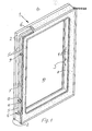
- An insulating glazing designated as a whole by 1, has two glass panes 2 and a frame 3 which keeps them at a distance and which is filled with desiccant. This can be seen from the fine perforations 4 on the inside of this frame 3.
- a frame 3 is provided which is formed from a single hollow profile by means of corresponding bends. However, it would also be possible to use individual frame parts, e.g. are mitred to make such a frame 3 and to implement the invention.
- a seal 5 is provided between the frame 3 and the panes 2 in a known manner.
- the outside of the frame 3 can be covered with sealing compound 6 in the manner shown in FIG. 1.
- the frame 3 has its webs 7 and 8 (FIGS. 2 to 4) which are not acted upon by the panes 2 and which have holes 9 in the exemplary embodiment, bores which provide ventilation and / or ventilation of the interior 10 between the glass panes 2 on the inside of the Allow frame 3.
- these perforations 9 are sealed gas-tight in the manner also indicated in FIG. 1, but above all in FIGS. 2 to 4.
- Fig. 1 is at the top of the two perforations 9 indicates and clearly shown in FIGS. 2 to 4 that the interior of the frame 3 in the immediate vicinity of the perforation 9 is filled with sealant 11, which forms the inner wall of the perforation 9 at least between the perforated webs 7 and 8.
- sealant 11 forms the inner wall of the perforation 9 at least between the perforated webs 7 and 8.
- the frame 3 can be completely filled with desiccant, although it has cross holes 9.
- a fitting 13 is provided in the perforation 9 and is in contact with the sealing compound 11, which can have different embodiments.
- This closure 13 displaces the sealing compound 11 delimiting the perforation 9 in the use position, so that an intimate and vapor-tight contact is produced between this sealant 11 and the closure 13 in the use position.
- a screw that cuts into the inner wall of sealing compound 11 with its thread 14 can be provided as the closure 13.
- 4 can be provided as a closure 13 with its outer contour with respect to the perforation 9, a comparatively enlarged, radially flexible plug which can be pressed into the perforation 9 and locked on the edges of the frame profile, in the exemplary embodiment of the web 7 lying outside in the use position is.
- the closure 13 has a head 15 which, in the closed position, bears against the outside of the frame 3, that is to say the web 7.
- the distance between the thickening 16 of the plug according to FIG. 4 and the head 15 corresponds approximately to that The thickness of the web 7 and a retraction 17 directly under the head 15 serve as a catch on this outer web 7.
- the sealing compound 11 is expediently a permanently tough elastic material such as butyl rubber. This makes it possible for the inner wall of the perforation 9 to have sufficient stability, but nevertheless to displace sealant 11 from the thread 14 or the enlarged diameter 16 of the stopper into the joints between the closure 13 and the outer, possibly also the inner, web of the frame profile is to achieve a hermetic seal and filling, as is indicated above all in FIGS. 2 to 4.
- the length of the closure 13 corresponds at least to the inside width of the frame profile between its two webs 7 and 8 in the longitudinal direction of the perforation 9.
- the closure 13, with its end facing the window interior 10, projects into the perforated cross section of the inner web 8 of the frame profile and in the exemplary embodiment is approximately flush with its inner surface facing the pane space 10. If necessary, a slightly curved end 18 can protrude slightly.
- the closure can be detachable, so that corrections to the internal pressure are possible during manufacture. If the closure 13 is a screw, it can be unscrewed, while the plug can be levered out by reaching under its head 15, since the plug is radially flexible. This is made possible, among other things, by the fact that the sealing compound remains permanently tough and elastic, so that a steam is subsequently added tight closure is possible.
- the closure 13 in turn, has an opening 19 in its longitudinal direction, at least partially passing through it and / or penetrable in the end region, for the temporary or permanent reception of a cannula 20 or the like.
- the opening 19 is continuous and there is also an inserted and soldered cannula 20.
- the stopper according to FIG. 4 shows an only partially through opening 19 which can be pushed through inwards if required. This opening also allows radial compliance.
- the cannula 20 can also be used to perform ventilation and venting even when the insulating glazing 1 is mounted in a holding frame. If necessary, it can also be hermetically and vapor-tightly closed at its outer end by soldering. In addition, it can be connectable to a pressure compensation system with its end facing away from the closure 13 if the insulating glazing 1 is to be able to be exposed to frequently changing pressures.
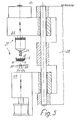
- the device 21 has a drill 22 with a drill 23 and a spray device 24 for the sealing compound 11 with a spray nozzle 25, which spray nozzle 25 fits into the hole 9 made by the drill 23 of the drill 22.
- the spray nozzle 25 is a cylindrical body, on the outside of which the outlet openings 26 for the material to be sprayed, that is to say the sealing compound 11, are arranged approximately radially and on both sides of this outlet Openings 26 located end areas 27 serve as a closure of the holes in the frame webs 7 and 8.
- the drill 23 and the spray nozzle 25 are aligned with one another on a common machine frame 28, but are arranged at a distance between them, into which the profile of the frame 3 - as indicated in FIG. 5 - fits, so that the drill 23 are then insertable from one side through the profile and the spray nozzle 25 from the opposite side into the drilled profile.
- the spraying device 24 has any metering device for the sprayed material, so that the correct amount is injected according to FIGS. 2 to 4.
- transverse holes 9 can be produced so that the holes 9 are first drilled into the frame 3 and, after the drill 23 has been withdrawn, the space between the perforated webs 7 and 8 of the frame profile around the bore area is sprayed with sealant 11.
- the spray nozzle 25 seals the perforations in the webs 7 and 8 itself.
- the sealant 11 is injected, the inner wall of the perforation 9 is formed by the spray nozzle 25 approximately flush with the bore edges in the profile webs 7 and 8.
Landscapes
- Engineering & Computer Science (AREA)
- Civil Engineering (AREA)
- Structural Engineering (AREA)
- Securing Of Glass Panes Or The Like (AREA)
- Refrigerator Housings (AREA)
Priority Applications (1)
| Application Number | Priority Date | Filing Date | Title |
|---|---|---|---|
| AT85114901T ATE51674T1 (de) | 1984-12-15 | 1985-11-25 | Abstandhaltender rahmen fuer eine isolierverglasung. |
Applications Claiming Priority (2)
| Application Number | Priority Date | Filing Date | Title |
|---|---|---|---|
| DE3445838 | 1984-12-15 | ||
| DE3445838A DE3445838C1 (de) | 1984-12-15 | 1984-12-15 | Abstandhalterrahmen fuer die Scheiben einer Isolierverglasung |
Publications (3)
| Publication Number | Publication Date |
|---|---|
| EP0185222A2 true EP0185222A2 (fr) | 1986-06-25 |
| EP0185222A3 EP0185222A3 (en) | 1987-03-25 |
| EP0185222B1 EP0185222B1 (fr) | 1990-04-04 |
Family
ID=6252890
Family Applications (1)
| Application Number | Title | Priority Date | Filing Date |
|---|---|---|---|
| EP85114901A Expired - Lifetime EP0185222B1 (fr) | 1984-12-15 | 1985-11-25 | Châssis écarteur pour un vitrage isolant |
Country Status (5)
| Country | Link |
|---|---|
| US (1) | US4817354A (fr) |
| EP (1) | EP0185222B1 (fr) |
| AT (1) | ATE51674T1 (fr) |
| CA (1) | CA1287272C (fr) |
| DE (2) | DE3445838C1 (fr) |
Cited By (4)
| Publication number | Priority date | Publication date | Assignee | Title |
|---|---|---|---|---|
| EP0266607A1 (fr) * | 1986-10-31 | 1988-05-11 | Schott Glaswerke | Système d'équilibrage des pressions dans des vitrages pare-feu |
| GB2264141A (en) * | 1992-02-11 | 1993-08-18 | Jonathon Milsom | Glazed unit with safety valve |
| EP0615045A1 (fr) * | 1993-03-12 | 1994-09-14 | Peter Lisec | Raccord électrique |
| WO2019025042A1 (fr) | 2017-07-31 | 2019-02-07 | Saint-Gobain Glass France | Procédé de fabrication d'un vitrage isolant |
Families Citing this family (31)
| Publication number | Priority date | Publication date | Assignee | Title |
|---|---|---|---|---|
| DE8707395U1 (de) * | 1987-05-22 | 1987-11-12 | Bischof, Hubert, 8033 Krailling | Isolierglasscheibe |
| DE3806648A1 (de) * | 1988-03-02 | 1989-10-05 | Edmund Trippner | Isolierglasfenster mit lichtschutzvorrichtung |
| US5761946A (en) * | 1992-06-30 | 1998-06-09 | Ppg Industries, Inc. | Method of making spacer stock |
| US5177916A (en) * | 1990-09-04 | 1993-01-12 | Ppg Industries, Inc. | Spacer and spacer frame for an insulating glazing unit and method of making same |
| US5255481A (en) | 1990-09-04 | 1993-10-26 | Ppg Industries, Inc. | Spacer and spacer frame for an insulating glazing unit and method of making same |
| US5675944A (en) * | 1990-09-04 | 1997-10-14 | P.P.G. Industries, Inc. | Low thermal conducting spacer assembly for an insulating glazing unit and method of making same |
| SE501409C2 (sv) * | 1992-01-15 | 1995-02-06 | Rasmussen Kurt Hegelund | Anordning för framställning av gasisolerade fönster |
| GB9218150D0 (en) | 1992-08-26 | 1992-10-14 | Pilkington Glass Ltd | Insulating units |
| IT1266114B1 (it) * | 1993-08-02 | 1996-12-20 | For El Base Di Vianello Fortun | Dispositivo per il riempimento di telai distanziatori per vetro-camera con materiale igroscopico |
| US5855972A (en) * | 1993-11-12 | 1999-01-05 | Kaeding; Konrad H | Sealant strip useful in the fabrication of insulated glass and compositions and methods relating thereto |
| CA2327842A1 (fr) * | 2000-12-07 | 2002-06-07 | Tec-N-Tec Inc. | Dispositif d'etancheite pour assemblage de fenetre a double vitrage |
| US6686002B2 (en) | 2001-01-11 | 2004-02-03 | Seal-Ops, Llc | Sealing strip composition |
| US7244479B2 (en) * | 2001-01-11 | 2007-07-17 | Seal-Ops, Llc | Sealing strip composition |
| US6916392B2 (en) | 2001-06-21 | 2005-07-12 | Cardinal Ig Company | Producing and servicing insulating glass units |
| WO2003024192A2 (fr) * | 2001-09-14 | 2003-03-27 | Darell Wayne Fields | Module de fenetre sans cadre |
| US6804924B2 (en) * | 2001-10-12 | 2004-10-19 | Cardinal Ig Company | Repair of insulating glass units |
| US6868648B2 (en) * | 2002-04-04 | 2005-03-22 | Bowmead Holdings Inc. | Fenestration sealed frame, insulating glazing panels |
| WO2004022872A1 (fr) * | 2002-09-04 | 2004-03-18 | Penn State Research Foundation | Panneau de verre resistant aux avaries et aux dommages |
| USD500863S1 (en) | 2003-11-04 | 2005-01-11 | Arch-It, Incorporated | Radius corner form |
| US7246411B2 (en) * | 2003-12-19 | 2007-07-24 | Jeld-Wen, Inc. | Methods and systems for sliding windows and doors |
| GB2415989B (en) * | 2004-06-29 | 2007-10-17 | Hickman James A A | Double glazed units with reproduction crown glass |
| US20060272171A1 (en) * | 2005-06-07 | 2006-12-07 | David Ferracuti | De-misting system for multi-pane glazing |
| GB2432871B (en) * | 2005-11-21 | 2010-04-07 | Denis Augustine Carey | A Process for Producing Double Glazed Glass Panels |
| GB0610634D0 (en) | 2006-05-30 | 2006-07-05 | Dow Corning | Insulating glass unit |
| GB0714257D0 (en) * | 2007-07-23 | 2007-08-29 | Dow Corning | Sealant for insulating glass unit |
| US20090094932A1 (en) * | 2007-10-05 | 2009-04-16 | Pedersen Mark E | Wall Drying Method and Apparatus |
| US10337235B2 (en) * | 2015-05-29 | 2019-07-02 | Integrated Automation Systems, Llc | Insulating glass unit and a method and apparatus for filling and sealing same |
| KR102119987B1 (ko) * | 2015-10-13 | 2020-06-08 | 쌩-고벵 글래스 프랑스 | 멤브레인을 갖는 2개의 중공-프로파일 스트립을 연결하기 위한 커넥터 |
| PT3393308T (pt) | 2015-12-21 | 2020-11-13 | Saint Gobain | Elemento em vidro isolante para um armário frigorífico |
| PL3440299T3 (pl) | 2016-04-05 | 2021-09-27 | Saint-Gobain Glass France | Szyba zespolona do mebla chłodniczego |
| US20190249486A1 (en) * | 2018-02-13 | 2019-08-15 | Ged Integrated Solutions, Inc. | Insulating glass unit plug and installation method |
Family Cites Families (17)
| Publication number | Priority date | Publication date | Assignee | Title |
|---|---|---|---|---|
| BE546783A (fr) * | 1956-03-20 | |||
| DE1265385B (de) * | 1961-04-19 | 1968-04-04 | Libbey Owens Ford Glass Co | Verfahren zum Anpassen des Innendrucks der zwischen den parallel im Abstand mit an den Raendern umlaufendem Abstandshalter luftdicht gehaltenen Glasscheiben eingeschlossenen, getrockneten Luft von Mehrscheibenisolierglaesern an den Aussendruck, sowie Vorrichtungen zum Durchfuehren des Verfahrens |
| US3835615A (en) * | 1970-04-30 | 1974-09-17 | J King | Fastener joint construction |
| US3646981A (en) * | 1970-06-02 | 1972-03-07 | Amerace Esna Corp | Insert for sandwich panels |
| DE2537017C3 (de) * | 1975-08-20 | 1978-08-17 | Bfg Glassgroup, Paris | Abstandshalterrahmen für Isolierglaseinheiten |
| GB1578030A (en) * | 1976-08-26 | 1980-10-29 | Pilkington Brothers Ltd | Multiple glazing |
| US4137680A (en) * | 1977-06-08 | 1979-02-06 | Doonan R Dean | Hole plug for insulated injection wall holes |
| FR2423621A1 (fr) * | 1978-04-17 | 1979-11-16 | Saint Gobain | Entree de fils electriques a l'interieur d'un vitrage multiple |
| US4332243A (en) * | 1980-04-04 | 1982-06-01 | Morton Gutnick | Devices and methods for the prevention of transmission of venereal disease and non-gonococcal genital infections |
| DE3032825A1 (de) * | 1980-08-30 | 1982-03-25 | DCL Glass Consult GmbH, 8000 München | Verfahren und vorrichtung zum befuellen einer isolierglaseinheit mit einem fuellgas |
| DE8205852U1 (de) * | 1981-03-19 | 1982-12-09 | SPS Glasbau Seraphin Pümpel & Söhne GmbH, 6800 Feldkirch, Vorarlberg | Vorrichtung zum Erzeugen von Unter- bzw.Überdruck in dem Hohlraum zwischen den Scheiben bei der Herstellung von Isolierglasscheiben |
| US4520602A (en) * | 1981-08-03 | 1985-06-04 | Thermetic Glass, Inc. | Multi-pane sealed window and method for forming same |
| DE3143659A1 (de) * | 1981-11-04 | 1983-05-11 | Helmut Lingemann GmbH & Co, 5600 Wuppertal | Trockenmittelapplikation fuer eine isolierverglasung oder dergleichen sowie ein mit der trockenmittelapplikation gefuelltes abstandhalterprofil |
| FR2521630A1 (fr) * | 1982-02-15 | 1983-08-19 | Bordonado Francis | Procede et element en vue de la realisation des cadres intermediaires pour vitrages multiples |
| US4462194A (en) * | 1982-07-30 | 1984-07-31 | Sprinkmann Sons Corporation | Building panel with cantilevered retaining members |
| DE3233399A1 (de) * | 1982-09-09 | 1984-03-15 | Helmut Lingemann GmbH & Co, 5600 Wuppertal | Verbindung zweier abstandhalterrahmenprofile sowie verfahren und vorrichtung zur herstellung der verbindung |
| AT378234B (de) * | 1983-10-24 | 1985-07-10 | Glas Marte Ges M B H & Co Kg | Verschlussstopfen fuer injektionsbohrungen an distanzhalterahmen fuer isolierglasscheiben |
-
1984
- 1984-12-15 DE DE3445838A patent/DE3445838C1/de not_active Expired - Lifetime
-
1985
- 1985-11-25 AT AT85114901T patent/ATE51674T1/de active
- 1985-11-25 EP EP85114901A patent/EP0185222B1/fr not_active Expired - Lifetime
- 1985-11-25 DE DE8585114901T patent/DE3576981D1/de not_active Expired - Fee Related
- 1985-12-13 CA CA000497581A patent/CA1287272C/fr not_active Expired - Lifetime
-
1987
- 1987-04-09 US US07/036,186 patent/US4817354A/en not_active Expired - Fee Related
Cited By (4)
| Publication number | Priority date | Publication date | Assignee | Title |
|---|---|---|---|---|
| EP0266607A1 (fr) * | 1986-10-31 | 1988-05-11 | Schott Glaswerke | Système d'équilibrage des pressions dans des vitrages pare-feu |
| GB2264141A (en) * | 1992-02-11 | 1993-08-18 | Jonathon Milsom | Glazed unit with safety valve |
| EP0615045A1 (fr) * | 1993-03-12 | 1994-09-14 | Peter Lisec | Raccord électrique |
| WO2019025042A1 (fr) | 2017-07-31 | 2019-02-07 | Saint-Gobain Glass France | Procédé de fabrication d'un vitrage isolant |
Also Published As
| Publication number | Publication date |
|---|---|
| EP0185222A3 (en) | 1987-03-25 |
| DE3445838C1 (de) | 1990-01-25 |
| ATE51674T1 (de) | 1990-04-15 |
| CA1287272C (fr) | 1991-08-06 |
| US4817354A (en) | 1989-04-04 |
| DE3576981D1 (de) | 1990-05-10 |
| EP0185222B1 (fr) | 1990-04-04 |
Similar Documents
| Publication | Publication Date | Title |
|---|---|---|
| EP0185222B1 (fr) | Châssis écarteur pour un vitrage isolant | |
| DD154812A5 (de) | Mehrscheiben-isolierglas und verfahren zu seiner herstellung | |
| EP1911925B1 (fr) | Cadre pour fenêtres, portes, éléments de façades ou analogues | |
| EP0114222A2 (fr) | Cadre de porte ou de fenêtre fabriqué en profilés creux, de préférence en profilés composés calorifuges, avec au moins un petit bois | |
| EP1026357B1 (fr) | Profilé d'encadrement pour fenêtres ou portes en bois-métal | |
| DE102012006899A1 (de) | Stoßverbindung vorzugsweise eines Fensterrahmens | |
| DE29620153U1 (de) | Verbindung für winklig aneinanderstoßende Hohlprofilstäbe | |
| DE19544077C2 (de) | Gegen Hitzeeinwirkung widerstandsfähige Verglasung | |
| DE1262550B (de) | Faltprofil-Dichtungsstrang zum Eindruecken in Bauwerksfugen und Verfahren zum Eindruecken desselben | |
| DE8608396U1 (de) | Injektionsschlauch für Betonfugen | |
| EP0110295A2 (fr) | Cadre d'espacement pour vitrage isolant dont les bords sont collés | |
| EP3524103A1 (fr) | Support pour fleurs et produits décoratifs sur les battants de fenêtre et de porte | |
| DE2537017A1 (de) | Abstandshalterrahmen fuer isolierglaseinheiten und dergleichen | |
| DE19940574C1 (de) | Anordnung zur Bildung einer Kreuzverbindung zwischen einem Längspfosten und einem Querpfosten bei einem Fenster oder einer Türe aus Kunststoff oder Leichtmetall | |
| EP0172575A2 (fr) | Dispositif d'assemblage | |
| DE9201532U1 (de) | Geradverbinder für hohle Abstandsprofile von Mehrscheibenisoliergläsern | |
| DE9016592U1 (de) | Geradverbinder, insbesondere aus Kunststoff, zur Verbindung von hohlen Abstandsprofilen und hohlen Sprossenprofilen eines Mehrscheibenisolierglases | |
| DE3041996A1 (de) | Einrichtung zur verbindung eines traegers fuer einen stockbandteil mit einer metallischen zarge | |
| EP0071874A1 (fr) | Battant de fenêtre ou de porte avec des croisillons factices amovibles | |
| DE8400332U1 (de) | Eck- oder stossverbinder fuer bauprofile | |
| EP1787002A1 (fr) | Ensemble d'elements comprenant au moins un meneau et au moins deux pieces d'extremite de meneau a integrer dans une vitre isolante | |
| DE2615746A1 (de) | Eckwinkel fuer abstandshalterprofile von isolierglasscheiben | |
| DE7933613U1 (de) | Von einem rahmen aus kunststoff- profilstaeben umgebene isolierglaseinheit | |
| DE10109718C1 (de) | Eckverbinder | |
| DE7345540U (de) | Eckwinkel zur Verbindung von Abstandshaltern |
Legal Events
| Date | Code | Title | Description |
|---|---|---|---|
| PUAI | Public reference made under article 153(3) epc to a published international application that has entered the european phase |
Free format text: ORIGINAL CODE: 0009012 |
|
| AK | Designated contracting states |
Kind code of ref document: A2 Designated state(s): AT BE CH DE FR GB IT LI LU NL SE |
|
| PUAL | Search report despatched |
Free format text: ORIGINAL CODE: 0009013 |
|
| AK | Designated contracting states |
Kind code of ref document: A3 Designated state(s): AT BE CH DE FR GB IT LI LU NL SE |
|
| 17P | Request for examination filed |
Effective date: 19870209 |
|
| 17Q | First examination report despatched |
Effective date: 19890614 |
|
| ITF | It: translation for a ep patent filed | ||
| GRAA | (expected) grant |
Free format text: ORIGINAL CODE: 0009210 |
|
| AK | Designated contracting states |
Kind code of ref document: B1 Designated state(s): AT BE CH DE FR GB IT LI LU NL SE |
|
| REF | Corresponds to: |
Ref document number: 51674 Country of ref document: AT Date of ref document: 19900415 Kind code of ref document: T |
|
| REF | Corresponds to: |
Ref document number: 3576981 Country of ref document: DE Date of ref document: 19900510 |
|
| ET | Fr: translation filed | ||
| GBT | Gb: translation of ep patent filed (gb section 77(6)(a)/1977) | ||
| PG25 | Lapsed in a contracting state [announced via postgrant information from national office to epo] |
Ref country code: LU Free format text: LAPSE BECAUSE OF NON-PAYMENT OF DUE FEES Effective date: 19901130 |
|
| PLBI | Opposition filed |
Free format text: ORIGINAL CODE: 0009260 |
|
| 26 | Opposition filed |
Opponent name: GLASTECHNISCHE INDUSTRIE PETER LISEC GMBH, Effective date: 19910103 |
|
| NLR1 | Nl: opposition has been filed with the epo |
Opponent name: GLASTECHNISCHE INDUSTRIE PETER LISEC GMBH |
|
| ITTA | It: last paid annual fee | ||
| PGFP | Annual fee paid to national office [announced via postgrant information from national office to epo] |
Ref country code: SE Payment date: 19931020 Year of fee payment: 9 |
|
| PGFP | Annual fee paid to national office [announced via postgrant information from national office to epo] |
Ref country code: FR Payment date: 19931027 Year of fee payment: 9 |
|
| PGFP | Annual fee paid to national office [announced via postgrant information from national office to epo] |
Ref country code: GB Payment date: 19931119 Year of fee payment: 9 |
|
| PGFP | Annual fee paid to national office [announced via postgrant information from national office to epo] |
Ref country code: NL Payment date: 19931130 Year of fee payment: 9 |
|
| PGFP | Annual fee paid to national office [announced via postgrant information from national office to epo] |
Ref country code: BE Payment date: 19931228 Year of fee payment: 9 |
|
| PG25 | Lapsed in a contracting state [announced via postgrant information from national office to epo] |
Ref country code: GB Effective date: 19941125 |
|
| PG25 | Lapsed in a contracting state [announced via postgrant information from national office to epo] |
Ref country code: SE Effective date: 19941126 |
|
| PG25 | Lapsed in a contracting state [announced via postgrant information from national office to epo] |
Ref country code: BE Effective date: 19941130 |
|
| PGFP | Annual fee paid to national office [announced via postgrant information from national office to epo] |
Ref country code: CH Payment date: 19941201 Year of fee payment: 10 |
|
| EAL | Se: european patent in force in sweden |
Ref document number: 85114901.3 |
|
| BERE | Be: lapsed |
Owner name: FRANZ XAVER BAYER ISOLIERGLASFABRIK K.G. Effective date: 19941130 |
|
| PG25 | Lapsed in a contracting state [announced via postgrant information from national office to epo] |
Ref country code: NL Effective date: 19950601 |
|
| NLV4 | Nl: lapsed or anulled due to non-payment of the annual fee | ||
| GBPC | Gb: european patent ceased through non-payment of renewal fee |
Effective date: 19941125 |
|
| PG25 | Lapsed in a contracting state [announced via postgrant information from national office to epo] |
Ref country code: FR Effective date: 19950731 |
|
| EUG | Se: european patent has lapsed |
Ref document number: 85114901.3 |
|
| REG | Reference to a national code |
Ref country code: FR Ref legal event code: ST |
|
| PG25 | Lapsed in a contracting state [announced via postgrant information from national office to epo] |
Ref country code: LI Effective date: 19951130 Ref country code: CH Effective date: 19951130 |
|
| PLBO | Opposition rejected |
Free format text: ORIGINAL CODE: EPIDOS REJO |
|
| PLBN | Opposition rejected |
Free format text: ORIGINAL CODE: 0009273 |
|
| STAA | Information on the status of an ep patent application or granted ep patent |
Free format text: STATUS: OPPOSITION REJECTED |
|
| 27O | Opposition rejected |
Effective date: 19960227 |
|
| REG | Reference to a national code |
Ref country code: CH Ref legal event code: PL |
|
| APAC | Appeal dossier modified |
Free format text: ORIGINAL CODE: EPIDOS NOAPO |
|
| APAC | Appeal dossier modified |
Free format text: ORIGINAL CODE: EPIDOS NOAPO |
|
| PGFP | Annual fee paid to national office [announced via postgrant information from national office to epo] |
Ref country code: DE Payment date: 19971113 Year of fee payment: 13 |
|
| PGFP | Annual fee paid to national office [announced via postgrant information from national office to epo] |
Ref country code: AT Payment date: 19971130 Year of fee payment: 13 |
|
| PG25 | Lapsed in a contracting state [announced via postgrant information from national office to epo] |
Ref country code: AT Free format text: LAPSE BECAUSE OF NON-PAYMENT OF DUE FEES Effective date: 19981125 |
|
| PG25 | Lapsed in a contracting state [announced via postgrant information from national office to epo] |
Ref country code: DE Free format text: LAPSE BECAUSE OF NON-PAYMENT OF DUE FEES Effective date: 19990901 |
|
| APAH | Appeal reference modified |
Free format text: ORIGINAL CODE: EPIDOSCREFNO |