EP0185291B1 - Dispositif de réglage pour minuterie - Google Patents
Dispositif de réglage pour minuterie Download PDFInfo
- Publication number
- EP0185291B1 EP0185291B1 EP19850115675 EP85115675A EP0185291B1 EP 0185291 B1 EP0185291 B1 EP 0185291B1 EP 19850115675 EP19850115675 EP 19850115675 EP 85115675 A EP85115675 A EP 85115675A EP 0185291 B1 EP0185291 B1 EP 0185291B1
- Authority
- EP
- European Patent Office
- Prior art keywords
- disk
- setting device
- timepiece
- casing
- clockwork
- Prior art date
- Legal status (The legal status is an assumption and is not a legal conclusion. Google has not performed a legal analysis and makes no representation as to the accuracy of the status listed.)
- Expired - Lifetime
Links
- 239000006059 cover glass Substances 0.000 claims description 7
- 239000011324 bead Substances 0.000 claims description 6
- 210000004905 finger nail Anatomy 0.000 claims 1
- 230000005764 inhibitory process Effects 0.000 description 5
- 238000000034 method Methods 0.000 description 4
- 230000000903 blocking effect Effects 0.000 description 2
- 239000000428 dust Substances 0.000 description 2
- 238000011109 contamination Methods 0.000 description 1
- 238000010411 cooking Methods 0.000 description 1
- 230000003203 everyday effect Effects 0.000 description 1
- 238000012544 monitoring process Methods 0.000 description 1
- 230000003287 optical effect Effects 0.000 description 1
- 230000035515 penetration Effects 0.000 description 1
- 230000002093 peripheral effect Effects 0.000 description 1
- 239000010453 quartz Substances 0.000 description 1
- VYPSYNLAJGMNEJ-UHFFFAOYSA-N silicon dioxide Inorganic materials O=[Si]=O VYPSYNLAJGMNEJ-UHFFFAOYSA-N 0.000 description 1
- 239000012780 transparent material Substances 0.000 description 1
- 238000004804 winding Methods 0.000 description 1
Images


Classifications
-
- G—PHYSICS
- G04—HOROLOGY
- G04F—TIME-INTERVAL MEASURING
- G04F3/00—Apparatus which can be set and started to measure-off predetermined or adjustably-fixed time intervals with driving mechanisms, e.g. dosimeters with clockwork
Definitions
- the invention relates to an adjusting device for a watch according to the preamble of protection claim 1 or 5.
- Such clocks which have only one hand, are known to almost everyone from everyday life, for example as a so-called short-time meter with an adjustment range of up to 60 minutes for the bathroom, for monitoring cooking or roasting processes in the kitchen and also from their use in the control of procedures in the laboratory. After the set time interval has elapsed, such clocks generally emit an acoustic signal, or, as is known from DE-A 3 315 545, an additional optical signal.
- the adjusting device contains either an outer adjusting ring or an inner adjusting disc with a strongly shaped adjusting knob as an adjusting element.
- short-time meters are carried around by the person responsible for observing a certain time schedule in a pocket of their clothing, for example in order to be able to carry out other work at a different location during the course of the set time interval.
- the previously known short-time meters can be mechanically inhibited when carried around in a pocket of clothing due to the exposed actuating element that moves when the set time interval is passed. This means that the sequence of the timepiece's clockwork is prevented or even blocked, which leads to extremely undesirable timeouts for the respective process to be monitored. This danger is greater the smaller the drive torque of the clockwork and the greater the extension of the actuating element running perpendicular to the drive axis and thus the corresponding braking torque.
- Quartz-controlled short-time meters equipped with an electromechanical converter can only deliver a lower drive torque than mechanically driven movements. Therefore, the former are even more at risk of hindering and locking the retracting movement.
- this known short-time meter has two further disadvantages.
- the actuating device according to the invention also offers significantly greater protection against inadvertent adjustment of the set time interval even in cases where mechanical inhibition can be practically ruled out.
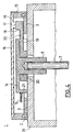
- FIG. 1 shows a timer 1, the housing front 26 of which has an annular bead 2.
- a circular dial 3 which has a minute division from 0 to 60.
- a circular adjusting disc 4 with a pointer 5 formed thereon is rotatably arranged.
- the shim 4 is positively and non-positively connected to the single pointer shaft 7 of the clockwork, which is no longer shown, by means of a bushing 6 which is also molded onto it.
- the circular dial 3 is covered by a likewise circular, transparent cover glass 8, which is snapped on its outer edge into a recess 9 of the bead 2 in a force-fitting and form-fitting manner and which in the area of the adjusting disc 4 has one inwards directed edge surface 11 of the shim 4 overlaps.
- the outer diameter of the dial 4 and the width of the annular cover glass 8 are so closely matched that, due to the small gap 25 that is formed, dust-proof covering of the dial 3 and thus also of the clockwork located below the dial 4 is achieved.
- the outer contour of the cover glass 8 is so far above the top of the shim 4 that both mechanical inhibition of the clockwork and penetration of dirt or dust into it is almost impossible.
- the adjusting disc 4 On its upper side, the adjusting disc 4 has a depression 12 with a molded-on rib 13, which facilitates rotation of the adjusting disc 4 and thus of the pointer, for example, by the user of the short-time meter engaging the tip of a finger.
- the timer is set and started by turning the dial 4 clockwise until the pointer 5 indicates the time interval to be measured, for example 20 minutes.
- the electrical clockwork is started by closing an electrical contact (not shown) or, in the case of mechanical watches, by the associated winding process, which leads to the pointer 5 countering clockwise and will have returned to the zero position after the indicated time interval.
- an alarm signal is generated in an electroacoustic manner or else a mechanically generated signal for a specific time.
- FIGS. 3-5 The embodiment of the actuating device according to the invention described in FIGS. 3-5 can also be used for the short-time meter functioning as described above.
- a driving disk 14 is connected to the pointer shaft 7 of the clockwork in this embodiment.
- the drive plate 14 is in turn a pointer 5 formed.
- the driving disk has on its side surface 21 diametrically opposite the pointer 5 a recess 19 in which an arm 20 mounted around the bushing 6 can be moved over an angular range given by the dimension of the recess 19.
- the arm 20 has a nose 18 at its end facing away from the socket 6.
- Both the dial 3 and the drive plate 14 are completely covered by a cover plate 16, which consists of transparent material.
- the cover plate 16 itself is firmly pressed into a knurled adjusting ring 15, which in turn is secured against a certain resistance on the bead 2 by technical means, not specified.
- the cover disk 16 has a projection 17 on its side facing the dial 3.
- the projection 17 and the nose 18 are dimensioned such that the cover disk 16 which can be rotated clockwise or counterclockwise by the user with the aid of the adjusting ring 15 moves the driving disk 14 in such a way that the projection 17 against the nose 18 from the right or left strikes.
- the adjusting ring 15 engages on the bead 2 by technical means, not shown here, in a certain rotational position.
- the recess 19 on the side surface of the driving disk 14 is important for those cases in which time intervals in the range of almost 60 minutes are to be set.
- the adjusting ring 15 For the setting of 60 minutes, for example, the adjusting ring 15 must first be rotated clockwise through 360 °, the projection 17 being in contact with the nose 18 from the right (see FIG. 3). If you turn the adjusting ring 15 counterclockwise, after a rotation of less than 360 °, the projection 17 is already on the nose 18 from the left again, the adjusting ring 15 is therefore not locked in the starting position again without the set time would be changed. During the last minutes of the movement of the clock mechanism, the nose 18 would then open against the projection 17 from the left if the adjusting ring 15 were not completely reset to run. This would have the consequence that the adjusting ring 15, which is necessarily in the latching position for the complete return of the driving disk 14, cannot be turned back into this position after a few minutes, but only after a few minutes.
- the arm 20 and thus the nose 18 can now be rotated through a certain angular range. If the angular range is selected such that the projection 17 overlaps both when it stops from the right (the arm 20 lies on the left boundary of the recess 19) and when it stops from the left (the arm 20 lies on the right boundary of the recess 19) the same place on the dial 3, the adjusting ring 15 can be brought back into its latching position immediately, even for times to be set of up to 60 minutes.
Landscapes
- Physics & Mathematics (AREA)
- General Physics & Mathematics (AREA)
- Measurement Of Predetermined Time Intervals (AREA)
Claims (7)
Applications Claiming Priority (2)
| Application Number | Priority Date | Filing Date | Title |
|---|---|---|---|
| DE19848436475 DE8436475U1 (de) | 1984-12-13 | 1984-12-13 | Stellvorrichtung für einen Kurzzeitmesser |
| DE8436475U | 1984-12-13 |
Publications (3)
| Publication Number | Publication Date |
|---|---|
| EP0185291A2 EP0185291A2 (fr) | 1986-06-25 |
| EP0185291A3 EP0185291A3 (en) | 1988-07-06 |
| EP0185291B1 true EP0185291B1 (fr) | 1990-01-31 |
Family
ID=6773709
Family Applications (1)
| Application Number | Title | Priority Date | Filing Date |
|---|---|---|---|
| EP19850115675 Expired - Lifetime EP0185291B1 (fr) | 1984-12-13 | 1985-12-10 | Dispositif de réglage pour minuterie |
Country Status (2)
| Country | Link |
|---|---|
| EP (1) | EP0185291B1 (fr) |
| DE (1) | DE8436475U1 (fr) |
Families Citing this family (1)
| Publication number | Priority date | Publication date | Assignee | Title |
|---|---|---|---|---|
| DE69230649T2 (de) * | 1991-05-10 | 2000-09-21 | Omron Corp., Kyoto | Zeitmesser mit Zifferblatt |
Family Cites Families (5)
| Publication number | Priority date | Publication date | Assignee | Title |
|---|---|---|---|---|
| US3146440A (en) * | 1959-11-27 | 1964-08-25 | Raytheon Co | Indicating apparatus |
| US3160719A (en) * | 1962-10-31 | 1964-12-08 | Automatic Timing & Controls | Timing or similar apparatus |
| US3693119A (en) * | 1970-09-25 | 1972-09-19 | Katuhiko Nakama | Electrical timing device |
| JPS5869294U (ja) * | 1981-11-02 | 1983-05-11 | 株式会社精工舎 | 先進セツト機構付タイマ |
| DE3315545A1 (de) * | 1982-04-29 | 1983-11-03 | Erwin 3500 Kassel Olmer | Zeitmessgeraet, insbesondere fuer frisiersalons |
-
1984
- 1984-12-13 DE DE19848436475 patent/DE8436475U1/de not_active Expired
-
1985
- 1985-12-10 EP EP19850115675 patent/EP0185291B1/fr not_active Expired - Lifetime
Also Published As
| Publication number | Publication date |
|---|---|
| EP0185291A3 (en) | 1988-07-06 |
| DE8436475U1 (de) | 1985-03-14 |
| EP0185291A2 (fr) | 1986-06-25 |
Similar Documents
| Publication | Publication Date | Title |
|---|---|---|
| DE69725984T2 (de) | Einstellvorrichtung mit hilfe einer krone für uhren | |
| DE2853786C2 (fr) | ||
| EP0360963B1 (fr) | Montre | |
| DE1123170B (de) | Vorrichtung zum Anzeigen der Winkelstellung und der Anzahl der erfolgten ganzen Umdrehungen einer Welle | |
| DE2518504C3 (de) | Weckerwerk | |
| EP0185291B1 (fr) | Dispositif de réglage pour minuterie | |
| DE2204858B2 (fr) | ||
| DE2514842A1 (de) | Weckerwerk | |
| DE2904744A1 (de) | Elektrische zeigeruhr | |
| EP0513633B1 (fr) | Montre réveil | |
| DE2840690C2 (de) | Elektrische Schaltuhr mit einem Kurzzeit- und einem Langzeitprogrammträger | |
| DE102007011594B4 (de) | Zentrale Datumsvorrichtung | |
| DE2822468A1 (de) | Alarmzeitnachweiseinrichtung | |
| DE3101348C2 (fr) | ||
| DE2653081B2 (de) | Elektronische Uhr, insbesondere quarzgesteuerte Armbanduhr | |
| DE2443614A1 (de) | Zifferblattscheibe fuer schaltuhren | |
| DE2822250C3 (de) | Kalenderuhr mit analoger Anzeige | |
| DE2833802A1 (de) | Zeitmessgeraet mit weckvorrichtung, insbesondere weckeruhr | |
| DE3337575A1 (de) | Elektromechanischer kurzzeitgeber | |
| DE3817284C1 (en) | Wall clock | |
| DE2509884A1 (de) | Weckerwerk | |
| DE60006862T2 (de) | Uhr mit anzeige der wöchentlichen zyklen | |
| EP2874021B1 (fr) | Horloge avec affichage de l'heure analogique | |
| EP0854404A1 (fr) | Interrupteur horaire analogique | |
| DE2001292C3 (de) | Zeitschalter |
Legal Events
| Date | Code | Title | Description |
|---|---|---|---|
| PUAI | Public reference made under article 153(3) epc to a published international application that has entered the european phase |
Free format text: ORIGINAL CODE: 0009012 |
|
| AK | Designated contracting states |
Kind code of ref document: A2 Designated state(s): CH FR GB IT LI |
|
| PUAL | Search report despatched |
Free format text: ORIGINAL CODE: 0009013 |
|
| AK | Designated contracting states |
Kind code of ref document: A3 Designated state(s): CH FR GB IT LI |
|
| 17P | Request for examination filed |
Effective date: 19880723 |
|
| 17Q | First examination report despatched |
Effective date: 19890712 |
|
| ITF | It: translation for a ep patent filed | ||
| GRAA | (expected) grant |
Free format text: ORIGINAL CODE: 0009210 |
|
| AK | Designated contracting states |
Kind code of ref document: B1 Designated state(s): CH FR GB IT LI |
|
| GBT | Gb: translation of ep patent filed (gb section 77(6)(a)/1977) | ||
| ET | Fr: translation filed | ||
| PLBE | No opposition filed within time limit |
Free format text: ORIGINAL CODE: 0009261 |
|
| STAA | Information on the status of an ep patent application or granted ep patent |
Free format text: STATUS: NO OPPOSITION FILED WITHIN TIME LIMIT |
|
| ITTA | It: last paid annual fee | ||
| 26N | No opposition filed | ||
| PGFP | Annual fee paid to national office [announced via postgrant information from national office to epo] |
Ref country code: GB Payment date: 19911121 Year of fee payment: 7 |
|
| PGFP | Annual fee paid to national office [announced via postgrant information from national office to epo] |
Ref country code: FR Payment date: 19911127 Year of fee payment: 7 |
|
| PGFP | Annual fee paid to national office [announced via postgrant information from national office to epo] |
Ref country code: CH Payment date: 19920217 Year of fee payment: 7 |
|
| PG25 | Lapsed in a contracting state [announced via postgrant information from national office to epo] |
Ref country code: GB Effective date: 19921210 |
|
| PG25 | Lapsed in a contracting state [announced via postgrant information from national office to epo] |
Ref country code: LI Effective date: 19921231 Ref country code: CH Effective date: 19921231 |
|
| GBPC | Gb: european patent ceased through non-payment of renewal fee |
Effective date: 19921210 |
|
| PG25 | Lapsed in a contracting state [announced via postgrant information from national office to epo] |
Ref country code: FR Effective date: 19930831 |
|
| REG | Reference to a national code |
Ref country code: CH Ref legal event code: PL |
|
| REG | Reference to a national code |
Ref country code: FR Ref legal event code: ST |