EP0185305A2 - Jonction entre un câble à isolation extrudée et un câble à isolation à fluide diélectrique - Google Patents
Jonction entre un câble à isolation extrudée et un câble à isolation à fluide diélectrique Download PDFInfo
- Publication number
- EP0185305A2 EP0185305A2 EP85115747A EP85115747A EP0185305A2 EP 0185305 A2 EP0185305 A2 EP 0185305A2 EP 85115747 A EP85115747 A EP 85115747A EP 85115747 A EP85115747 A EP 85115747A EP 0185305 A2 EP0185305 A2 EP 0185305A2
- Authority
- EP
- European Patent Office
- Prior art keywords
- insulation
- insulator
- cable
- cross
- linked
- Prior art date
- Legal status (The legal status is an assumption and is not a legal conclusion. Google has not performed a legal analysis and makes no representation as to the accuracy of the status listed.)
- Granted
Links
Images
Classifications
-
- H—ELECTRICITY
- H02—GENERATION; CONVERSION OR DISTRIBUTION OF ELECTRIC POWER
- H02G—INSTALLATION OF ELECTRIC CABLES OR LINES, OR OF COMBINED OPTICAL AND ELECTRIC CABLES OR LINES
- H02G15/00—Cable fittings
- H02G15/20—Cable fittings for cables filled with or surrounded by gas or oil
- H02G15/24—Cable junctions
- H02G15/25—Stop junctions
-
- H—ELECTRICITY
- H02—GENERATION; CONVERSION OR DISTRIBUTION OF ELECTRIC POWER
- H02G—INSTALLATION OF ELECTRIC CABLES OR LINES, OR OF COMBINED OPTICAL AND ELECTRIC CABLES OR LINES
- H02G15/00—Cable fittings
- H02G15/20—Cable fittings for cables filled with or surrounded by gas or oil
- H02G15/24—Cable junctions
Definitions
- the present invention refers to a joint between the cable having an extruded insulation and the cable having an insulation aided by a dielectric fluid as the oil filled cables, the so-called "pipe” type cables, the gas-insulated cables and the compound-insulated cables, both of single-core and multi-core type cables.
- the joints used up to now to connect cables having an extruded insulation and cables having an insulation aided by a dielectric fluid comprise, at each end of the cables, a sealing end of specific type to finish the cable on which said sealing end is mounted, a mechanical and electrical connection between the lugs of the sealing ends and a metal box, filled with an insulating fluid, that tightly encloses the sealing ends.
- the greater encumbrance of the known joints of the type in question with respect to the known ones between cables of the same type is substantially due to the presence of the box filled with a dielectric fluid that encloses the two sealing ends fitted around the ends of the cable.
- the aim of the present invention is a joint between a cable having an extruded insulation and a cable having an insulation aided by a dielectric fluid that has the radial encumbrance smaller than the known ones and in particular an encumbrance in radial direction substantially of the same order of magnitude as that of the known joints by which the connection between cables of the same type is carried out and that has a simple structure and therefore is rapidly carried out and is reliable also when utilizing in the field of high voltages.
- the object of the present invention is a joint between cables having extruded insulation and cables having insulation aided by a dielectric fluid, characterized by the fact of comprising:
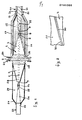
- the joint has a through insulator 1 constituted by a body of a compound based on epoxy resins of type known per se in which a central zone 2 and ends 3 and 4 tapered according to a truncated-cone configuration are noticed.
- the central zone 2 and the roots 18 of the ends 3 and 4 of the insulator are covered with a conductive varnish.
- the body of the through insulator 1 embeddes a metal bar 5, for instance of aluminium, whose ends 6 and 7 project from the ends 3 and 4 of the through insulator body.
- the previously described through insulator of a joint according to the invention has the same structure as that of the through insulators of the stop joints between oil-filled cables.
- the end 6 of the bar 5 of the through insulator 1 is connected, in a way known per se, for instance through a ferrule 8 or a welding and the like, to the conductor 9 of a cable having the insulation aided by a dielectric fluid as for instance an oil-filled cable 10.
- the end of the oil-filled cable 10 present in the joint is prepared by stepwise stripping for a part 12 the solid stratified insulation 11, giving it a truncated-cone tapered shape, the outer semiconductive layer 13 and the metal sheath 14 of the cable itself.
- the insulation 15 can be formed by a plurality of superimposed cylindrical sleeves, each of them is formed in place by winding paper tapes, radiusing each sleeve at the tapered surfaces of the through insulator and of the cable insulation through windings of crepe paper tapes.
- a semiconductive layer 16 encircles the insulation 15 up to overlap the outer semiconductive screen 13 of the oil-filled cable 10 and to the root 18 of the end 3 covered with a conductive varnish.
- a metal box 19 encloses the whole and is tightly connected at one part to the central zone 2 of the body of the through insulator 1 through a flange and counter-flange system 20 and at the other part is tightly connected to the metal sheath 14 of the oil-filled cable 10 by means of a welding 21.
- end 7 of the bar 5 of the through insulator 1 is mechanically and electrically connected to the conductor 22 of a cable having a cross-linked extruded insulation, for instance of compounds based on EPR, EPDM, by means of a ferrule 24 or a welding and the like.
- the end 23 of the cable having the cross-linked extruded insulation is tapered according to a truncated-cone configuration and besides the conductor and the insulator presents also the outer semiconductive screen 25 stepwise stripped.
- the insulation 27 covers also the truncated-cone tapered end of the insulation of the cable 23 and the end 4 of the through insulator 1, except the root 18 of said end that is covered with a conductive varnish.
- the insulation 27 is preferably formed by winding a plurality of cross-linkable material tapes, for instance of cross-linkable EPR that following their cross-linking, carried out under pressure after the formation of the insulation itself, gives rise to the formation of a monolithic and compact body and permits to obtain, with the expedients suggested by the known technique for the elastomer-working, a bond of chemico-physical nature between the end 26 of the extruded insulation cable and the insulation 27 itself.
- the insulation 27 covers also the end 4 of the through insulator 1 and is bonded to this latter through bonds of chemico-physical nature.
- the bond of chemico-physical nature between the insulation 27 and the end 4 of the through insulator 1 is preferably obtained by means of a layer of adhesive material 28 interposed between them which acts as a connecting bridge between the material of the through insulator constituted by a compound based on epoxy resins and the material of the insulation 27 constituted by a cross-linked elastomeric material, for instance of cross-linked EPR.
- the layer 28 can be formed by using an adhesive material which has the following properties:
- the adhesive material for the layer 28 can be that which results from the use of one of the different materials existing on the market to realize a bond between the materials based on epoxy resins and the material based on cross-linked EPR forming the cross-linked insulation.
- materials are the product commercially known as "4400” manufactured by HENKEL, and the product commercially known as "TIXON 508" manufactured by Dayton Chemical Division.
- a layer of semiconductive material 29 constituted for instance by a conductive varnish, covers the insulation 27 overlapping the semiconductive layer 25 of the extruded insulation cable 23 and the root of the end 4 of the through insulator covered with a conductive varnish.
- Figure 2 shows a particular of an alternative embodiment of a joint according to the present invention.
- a joint according to this alternative embodiment differs from the embodiment of figure 1 only in the manner of realizing the chemico-physical bond between the insulating material 27 and the end 4 of the through insulator.
- the bond between the just cited elements is obtained by forming two adhesive layers of different nature doubled together and precisely by a first adhesive layer 30 in direct contact with the surface of the end 4 of the through insulator 1 and by a layer 31 overlapped to the layer 30 and in direct contact with the insulation 27 of vulcanized material.
- the adhesive material forming the layer 30 is of a type suitable for realizing a chemico-physical adhesion particularly efficacious with the material based on epoxy resin of the through insulator 4, while the layer 31 is formed by means of an adhesive material particularly suitable for realizing a chemico-physical bond with the cross-linked elastomeric material, for instance of EPR of the layer 27.
- the adhesive materials forming the layers 30 and 31 are of type suitable for realizing between them a particularly efficacious chemico-physical adhesion.
- the layers 30 and 31 can be formed by means of adhesive materials having the following properties:
- the adhesive material for the layer 30 can be that which results from the use of one of the various materials existing on the market to realize a bond with the materials based on epoxy resins and the adhesives compatible for the bond with cross-linked materials based on EPR.
- the adhesive material for the layer 31 can be that which results from the use of one of the various materials existing on the market to realize a bond with the cross-linked materials based on EPR and the adhesives compatible for the bond with the materials based on epoxy resins.
- Examples of materials for the layer 30 are the product commercially known with “chemosil 211" manufactured by HEN KE L and the product commercially known with “THIXON 508" manufactured by Dayton Chemical Division.
- Examples of materials for the layers 31 are the product commercially known under the trade mark "X2311” manufactured by HENKEL and the product commercially known under the trade mark "P7” manufactured by Dayton Chemical Division.
- the through insulators to be provided will be as many as the cores of the cables to be connected are.
- central zones 2 could be closely connected to each other originating a single monolithic plate of an epoxy resin covered with a conductive varnish.
- said plate can be of metallic material for instance non-magnetic steel and foresee as many holes as the through insulators for tightly receiving these latter are.
- the joints according to the invention are of easy and simple realization since they are obtained by assembling together pre-fabricated elements, as the through insulators and the metal box and their realization involves a tape winding operation according to a known technique for the formation of the insulations.
- the close contact realized through the chemico-physical bonds between the material based on epoxy resins of the through insulator and the insulation encircling the mechanical and electrical connection of said through insulator with the extruded insulation cable permits to overcome those risks of perforations of the joint that could arise especially at high voltages in absence of said close contact owing to the possible presence of small quantities of air in the zone of contact between the above cited elements.
Landscapes
- Cable Accessories (AREA)
- Communication Cables (AREA)
- Processing Of Terminals (AREA)
- Insulated Conductors (AREA)
- Gas Or Oil Filled Cable Accessories (AREA)
- Manufacturing Of Electrical Connectors (AREA)
- Electric Cable Installation (AREA)
- Waveguide Aerials (AREA)
Priority Applications (1)
| Application Number | Priority Date | Filing Date | Title |
|---|---|---|---|
| AT85115747T ATE74236T1 (de) | 1984-12-17 | 1985-12-11 | Verbindung zwischen einem kabel mit extrudierter isolierung und einem kabel mit einer durch ein dielektrisches fluidum unterstuetzten isolierung. |
Applications Claiming Priority (2)
| Application Number | Priority Date | Filing Date | Title |
|---|---|---|---|
| IT24089/84A IT1177429B (it) | 1984-12-17 | 1984-12-17 | Giunto tra cavo ad isolante estruso e cavo con isolante assistito da un dielettrico fluido |
| IT2408984 | 1984-12-17 |
Publications (3)
| Publication Number | Publication Date |
|---|---|
| EP0185305A2 true EP0185305A2 (fr) | 1986-06-25 |
| EP0185305A3 EP0185305A3 (en) | 1989-04-19 |
| EP0185305B1 EP0185305B1 (fr) | 1992-03-25 |
Family
ID=11211925
Family Applications (1)
| Application Number | Title | Priority Date | Filing Date |
|---|---|---|---|
| EP85115747A Expired - Lifetime EP0185305B1 (fr) | 1984-12-17 | 1985-12-11 | Jonction entre un câble à isolation extrudée et un câble à isolation à fluide diélectrique |
Country Status (15)
| Country | Link |
|---|---|
| US (1) | US4642415A (fr) |
| EP (1) | EP0185305B1 (fr) |
| JP (1) | JPS61167325A (fr) |
| CN (1) | CN1004038B (fr) |
| AT (1) | ATE74236T1 (fr) |
| AU (1) | AU575286B2 (fr) |
| BR (1) | BR8506540A (fr) |
| CA (1) | CA1239674A (fr) |
| DE (1) | DE3585727D1 (fr) |
| ES (1) | ES291751Y (fr) |
| GR (1) | GR853019B (fr) |
| IT (1) | IT1177429B (fr) |
| MX (1) | MX159099A (fr) |
| NZ (2) | NZ214568A (fr) |
| SG (1) | SG102392G (fr) |
Cited By (1)
| Publication number | Priority date | Publication date | Assignee | Title |
|---|---|---|---|---|
| GB2201847A (en) * | 1987-02-16 | 1988-09-07 | Pirelli Brasil | Joining extruded cable to impregnated lapped cable |
Families Citing this family (5)
| Publication number | Priority date | Publication date | Assignee | Title |
|---|---|---|---|---|
| EP1222723B1 (fr) | 1999-10-11 | 2007-03-07 | Utilx Corporation | Connexions et terminaisons pour cables |
| CA2557169C (fr) * | 2004-03-01 | 2014-07-15 | Novinium, Inc. | Connexion haute pression pour cable d'alimentation |
| US7538274B2 (en) * | 2006-01-23 | 2009-05-26 | Novinium, Inc. | Swagable high-pressure cable connectors having improved sealing means |
| US10651637B2 (en) | 2014-03-21 | 2020-05-12 | Quanta Associates, L.P. | Flexible electrical isolation device |
| PE20180613A1 (es) * | 2014-03-21 | 2018-04-11 | Quanta Associates Lp | Dispositivo flexible para aislamiento electrico |
Family Cites Families (4)
| Publication number | Priority date | Publication date | Assignee | Title |
|---|---|---|---|---|
| GB782256A (en) * | 1955-06-15 | 1957-09-04 | Pirelli | Improvements in or relating to stop joints or terminals for multi-core high-tension electric cables |
| US4184005A (en) * | 1975-11-04 | 1980-01-15 | Henkel Kommanditgesellschaft Auf Aktien (Henkel Kgaa) | Process of solvent-free lamination using isocyanate/amine adhesives |
| DE2601545C3 (de) * | 1976-01-16 | 1979-08-09 | Felten & Guilleaume Carlswerk Ag, 5000 Koeln | Verbindungsmuffe für den Übergang von Papiermassekabeln auf kunststoffisolierte Kabel |
| US4234758A (en) * | 1978-11-03 | 1980-11-18 | Borg-Warner Corporation | Cable splice |
-
1984
- 1984-12-17 IT IT24089/84A patent/IT1177429B/it active
-
1985
- 1985-12-11 AT AT85115747T patent/ATE74236T1/de not_active IP Right Cessation
- 1985-12-11 DE DE8585115747T patent/DE3585727D1/de not_active Expired - Lifetime
- 1985-12-11 EP EP85115747A patent/EP0185305B1/fr not_active Expired - Lifetime
- 1985-12-14 CN CN85109023.0A patent/CN1004038B/zh not_active Expired
- 1985-12-16 CA CA000497777A patent/CA1239674A/fr not_active Expired
- 1985-12-16 NZ NZ214568A patent/NZ214568A/xx unknown
- 1985-12-16 US US06/809,156 patent/US4642415A/en not_active Expired - Fee Related
- 1985-12-16 AU AU51291/85A patent/AU575286B2/en not_active Ceased
- 1985-12-16 GR GR853019A patent/GR853019B/el not_active IP Right Cessation
- 1985-12-16 MX MX972A patent/MX159099A/es unknown
- 1985-12-17 ES ES1985291751U patent/ES291751Y/es not_active Expired
- 1985-12-17 JP JP60284198A patent/JPS61167325A/ja active Pending
- 1985-12-17 BR BR8506540A patent/BR8506540A/pt not_active IP Right Cessation
- 1985-12-17 NZ NZ214591A patent/NZ214591A/xx unknown
-
1992
- 1992-10-07 SG SG1023/92A patent/SG102392G/en unknown
Cited By (2)
| Publication number | Priority date | Publication date | Assignee | Title |
|---|---|---|---|---|
| GB2201847A (en) * | 1987-02-16 | 1988-09-07 | Pirelli Brasil | Joining extruded cable to impregnated lapped cable |
| GB2201847B (en) * | 1987-02-16 | 1991-02-06 | Pirelli Brasil | Cable jointing |
Also Published As
| Publication number | Publication date |
|---|---|
| SG102392G (en) | 1992-12-04 |
| IT1177429B (it) | 1987-08-26 |
| MX159099A (es) | 1989-04-18 |
| CA1239674A (fr) | 1988-07-26 |
| AU575286B2 (en) | 1988-07-21 |
| US4642415A (en) | 1987-02-10 |
| AU5129185A (en) | 1986-06-26 |
| NZ214591A (en) | 1988-10-28 |
| EP0185305A3 (en) | 1989-04-19 |
| JPS61167325A (ja) | 1986-07-29 |
| CN85109023A (zh) | 1986-10-01 |
| NZ214568A (en) | 1987-08-31 |
| ES291751U (es) | 1986-05-16 |
| IT8424089A0 (it) | 1984-12-17 |
| BR8506540A (pt) | 1986-09-09 |
| DE3585727D1 (de) | 1992-04-30 |
| ATE74236T1 (de) | 1992-04-15 |
| CN1004038B (zh) | 1989-04-26 |
| ES291751Y (es) | 1987-01-16 |
| GR853019B (fr) | 1986-04-15 |
| EP0185305B1 (fr) | 1992-03-25 |
| IT8424089A1 (it) | 1986-06-17 |
Similar Documents
| Publication | Publication Date | Title |
|---|---|---|
| EP0070696B1 (fr) | Connecteur pour jonction de câble et méthode | |
| JP5158754B2 (ja) | 光ケーブルシールド層接続部 | |
| US4348076A (en) | Fibre-optic cable joints | |
| JPS5821488B2 (ja) | ケ−ブル接続装置 | |
| US4518819A (en) | Clamp assembly for power cables | |
| EP0185305B1 (fr) | Jonction entre un câble à isolation extrudée et un câble à isolation à fluide diélectrique | |
| US11536252B2 (en) | Down conductor connection system, wind turbine lightning protection system, and method for arranging a down conductor connection system | |
| US6172304B1 (en) | Device for providing leakproof protection to a splice in a high voltage cable | |
| US4234756A (en) | Preterminated block system and method of installing same | |
| US4855536A (en) | Power cable having sectionalized screen and method of making same | |
| JPS58131610A (ja) | 電気ブツシングとその製造方法 | |
| US4638112A (en) | Stop joint for interconnecting two electrical cables of different types | |
| US2925459A (en) | Branch joint for electric cables | |
| GB2288696A (en) | Cable splice or termination | |
| CA1113558A (fr) | Aboutement de cables electriques a l'aide d'une composition durcissable mecaniquement rigide sous logement | |
| US4504695A (en) | Power cable joint | |
| EP0071482A1 (fr) | Ensemble de connexion et méthode pour câbles de puissance | |
| JP2683574B2 (ja) | 電力ケーブルの接続部 | |
| JPS6015392Y2 (ja) | 遮水層付電力ケ−ブルのソルダレス接続部 | |
| JP2023111882A (ja) | Hvdc電力ケーブル多分岐接合アセンブリ | |
| CN114389061A (zh) | 高压电缆接续方法 | |
| GB2110888A (en) | Oil filled electric cable system | |
| JPS59106813A (ja) | ケ−ブルの接続方法 | |
| KR20000060247A (ko) | 송전케이블용 절연통 보호장치 | |
| JPH08275368A (ja) | Y分岐ジョイント |
Legal Events
| Date | Code | Title | Description |
|---|---|---|---|
| PUAI | Public reference made under article 153(3) epc to a published international application that has entered the european phase |
Free format text: ORIGINAL CODE: 0009012 |
|
| AK | Designated contracting states |
Kind code of ref document: A2 Designated state(s): AT BE CH DE FR GB LI LU NL SE |
|
| PUAL | Search report despatched |
Free format text: ORIGINAL CODE: 0009013 |
|
| AK | Designated contracting states |
Kind code of ref document: A3 Designated state(s): AT BE CH DE FR GB LI LU NL SE |
|
| 17P | Request for examination filed |
Effective date: 19890925 |
|
| 17Q | First examination report despatched |
Effective date: 19901129 |
|
| RAP1 | Party data changed (applicant data changed or rights of an application transferred) |
Owner name: PIRELLI CAVI S.P.A. |
|
| GRAA | (expected) grant |
Free format text: ORIGINAL CODE: 0009210 |
|
| AK | Designated contracting states |
Kind code of ref document: B1 Designated state(s): AT BE CH DE FR GB LI LU NL SE |
|
| REF | Corresponds to: |
Ref document number: 74236 Country of ref document: AT Date of ref document: 19920415 Kind code of ref document: T |
|
| REF | Corresponds to: |
Ref document number: 3585727 Country of ref document: DE Date of ref document: 19920430 |
|
| ET | Fr: translation filed | ||
| PGFP | Annual fee paid to national office [announced via postgrant information from national office to epo] |
Ref country code: AT Payment date: 19921029 Year of fee payment: 8 |
|
| PGFP | Annual fee paid to national office [announced via postgrant information from national office to epo] |
Ref country code: SE Payment date: 19921118 Year of fee payment: 8 |
|
| PGFP | Annual fee paid to national office [announced via postgrant information from national office to epo] |
Ref country code: GB Payment date: 19921127 Year of fee payment: 8 Ref country code: CH Payment date: 19921127 Year of fee payment: 8 |
|
| PGFP | Annual fee paid to national office [announced via postgrant information from national office to epo] |
Ref country code: BE Payment date: 19921210 Year of fee payment: 8 |
|
| PGFP | Annual fee paid to national office [announced via postgrant information from national office to epo] |
Ref country code: LU Payment date: 19921215 Year of fee payment: 8 |
|
| PGFP | Annual fee paid to national office [announced via postgrant information from national office to epo] |
Ref country code: FR Payment date: 19921217 Year of fee payment: 8 |
|
| PLBE | No opposition filed within time limit |
Free format text: ORIGINAL CODE: 0009261 |
|
| STAA | Information on the status of an ep patent application or granted ep patent |
Free format text: STATUS: NO OPPOSITION FILED WITHIN TIME LIMIT |
|
| EPTA | Lu: last paid annual fee | ||
| 26N | No opposition filed | ||
| PG25 | Lapsed in a contracting state [announced via postgrant information from national office to epo] |
Ref country code: NL Effective date: 19930701 |
|
| NLV4 | Nl: lapsed or anulled due to non-payment of the annual fee | ||
| PG25 | Lapsed in a contracting state [announced via postgrant information from national office to epo] |
Ref country code: DE Effective date: 19930901 |
|
| PG25 | Lapsed in a contracting state [announced via postgrant information from national office to epo] |
Ref country code: LU Free format text: LAPSE BECAUSE OF NON-PAYMENT OF DUE FEES Effective date: 19931211 Ref country code: GB Effective date: 19931211 Ref country code: AT Effective date: 19931211 |
|
| PG25 | Lapsed in a contracting state [announced via postgrant information from national office to epo] |
Ref country code: SE Effective date: 19931212 |
|
| PG25 | Lapsed in a contracting state [announced via postgrant information from national office to epo] |
Ref country code: LI Effective date: 19931231 Ref country code: CH Effective date: 19931231 Ref country code: BE Effective date: 19931231 |
|
| BERE | Be: lapsed |
Owner name: PIRELLI CAVI S.P.A. Effective date: 19931231 |
|
| GBPC | Gb: european patent ceased through non-payment of renewal fee |
Effective date: 19931211 |
|
| PG25 | Lapsed in a contracting state [announced via postgrant information from national office to epo] |
Ref country code: FR Effective date: 19940831 |
|
| REG | Reference to a national code |
Ref country code: CH Ref legal event code: PL |
|
| REG | Reference to a national code |
Ref country code: FR Ref legal event code: ST |
|
| EUG | Se: european patent has lapsed |
Ref document number: 85115747.9 Effective date: 19940710 |