EP0185449A1 - Appareil de commande pour un moteur d'une fenêtre d'un véhicule automobile - Google Patents
Appareil de commande pour un moteur d'une fenêtre d'un véhicule automobile Download PDFInfo
- Publication number
- EP0185449A1 EP0185449A1 EP85307776A EP85307776A EP0185449A1 EP 0185449 A1 EP0185449 A1 EP 0185449A1 EP 85307776 A EP85307776 A EP 85307776A EP 85307776 A EP85307776 A EP 85307776A EP 0185449 A1 EP0185449 A1 EP 0185449A1
- Authority
- EP
- European Patent Office
- Prior art keywords
- flip
- flop
- input
- window
- motor
- Prior art date
- Legal status (The legal status is an assumption and is not a legal conclusion. Google has not performed a legal analysis and makes no representation as to the accuracy of the status listed.)
- Withdrawn
Links
- XUIMIQQOPSSXEZ-UHFFFAOYSA-N Silicon Chemical compound [Si] XUIMIQQOPSSXEZ-UHFFFAOYSA-N 0.000 claims abstract description 7
- 230000005669 field effect Effects 0.000 claims abstract description 7
- 229910052710 silicon Inorganic materials 0.000 claims abstract description 7
- 239000010703 silicon Substances 0.000 claims abstract description 7
- 239000003990 capacitor Substances 0.000 claims description 16
- 230000000630 rising effect Effects 0.000 claims description 3
- 238000001514 detection method Methods 0.000 claims description 2
- 230000002401 inhibitory effect Effects 0.000 claims 1
- 230000002441 reversible effect Effects 0.000 abstract description 4
- 239000004065 semiconductor Substances 0.000 abstract description 2
- 239000007787 solid Substances 0.000 description 6
- 230000003213 activating effect Effects 0.000 description 3
- 230000001276 controlling effect Effects 0.000 description 2
- 238000010586 diagram Methods 0.000 description 2
- 230000000694 effects Effects 0.000 description 2
- RYGMFSIKBFXOCR-UHFFFAOYSA-N Copper Chemical compound [Cu] RYGMFSIKBFXOCR-UHFFFAOYSA-N 0.000 description 1
- 230000033228 biological regulation Effects 0.000 description 1
- 238000010276 construction Methods 0.000 description 1
- 229910052802 copper Inorganic materials 0.000 description 1
- 239000010949 copper Substances 0.000 description 1
- 230000001939 inductive effect Effects 0.000 description 1
- 230000001105 regulatory effect Effects 0.000 description 1
Images

Classifications
-
- E—FIXED CONSTRUCTIONS
- E05—LOCKS; KEYS; WINDOW OR DOOR FITTINGS; SAFES
- E05F—DEVICES FOR MOVING WINGS INTO OPEN OR CLOSED POSITION; CHECKS FOR WINGS; WING FITTINGS NOT OTHERWISE PROVIDED FOR, CONCERNED WITH THE FUNCTIONING OF THE WING
- E05F15/00—Power-operated mechanisms for wings
- E05F15/60—Power-operated mechanisms for wings using electrical actuators
- E05F15/603—Power-operated mechanisms for wings using electrical actuators using rotary electromotors
- E05F15/665—Power-operated mechanisms for wings using electrical actuators using rotary electromotors for vertically-sliding wings
- E05F15/689—Power-operated mechanisms for wings using electrical actuators using rotary electromotors for vertically-sliding wings specially adapted for vehicle windows
- E05F15/695—Control circuits therefor
-
- H—ELECTRICITY
- H02—GENERATION; CONVERSION OR DISTRIBUTION OF ELECTRIC POWER
- H02H—EMERGENCY PROTECTIVE CIRCUIT ARRANGEMENTS
- H02H7/00—Emergency protective circuit arrangements specially adapted for specific types of electric machines or apparatus or for sectionalised protection of cable or line systems, and effecting automatic switching in the event of an undesired change from normal working conditions
- H02H7/08—Emergency protective circuit arrangements specially adapted for specific types of electric machines or apparatus or for sectionalised protection of cable or line systems, and effecting automatic switching in the event of an undesired change from normal working conditions for dynamo-electric motors
- H02H7/0833—Emergency protective circuit arrangements specially adapted for specific types of electric machines or apparatus or for sectionalised protection of cable or line systems, and effecting automatic switching in the event of an undesired change from normal working conditions for dynamo-electric motors for electric motors with control arrangements
- H02H7/0838—Emergency protective circuit arrangements specially adapted for specific types of electric machines or apparatus or for sectionalised protection of cable or line systems, and effecting automatic switching in the event of an undesired change from normal working conditions for dynamo-electric motors for electric motors with control arrangements with H-bridge circuit
-
- H—ELECTRICITY
- H02—GENERATION; CONVERSION OR DISTRIBUTION OF ELECTRIC POWER
- H02P—CONTROL OR REGULATION OF ELECTRIC MOTORS, ELECTRIC GENERATORS OR DYNAMO-ELECTRIC CONVERTERS; CONTROLLING TRANSFORMERS, REACTORS OR CHOKE COILS
- H02P7/00—Arrangements for regulating or controlling the speed or torque of electric DC motors
- H02P7/03—Arrangements for regulating or controlling the speed or torque of electric DC motors for controlling the direction of rotation of DC motors
- H02P7/04—Arrangements for regulating or controlling the speed or torque of electric DC motors for controlling the direction of rotation of DC motors by means of a H-bridge circuit
-
- E—FIXED CONSTRUCTIONS
- E05—LOCKS; KEYS; WINDOW OR DOOR FITTINGS; SAFES
- E05F—DEVICES FOR MOVING WINGS INTO OPEN OR CLOSED POSITION; CHECKS FOR WINGS; WING FITTINGS NOT OTHERWISE PROVIDED FOR, CONCERNED WITH THE FUNCTIONING OF THE WING
- E05F15/00—Power-operated mechanisms for wings
- E05F15/40—Safety devices, e.g. detection of obstructions or end positions
- E05F15/41—Detection by monitoring transmitted force or torque; Safety couplings with activation dependent upon torque or force, e.g. slip couplings
-
- E—FIXED CONSTRUCTIONS
- E05—LOCKS; KEYS; WINDOW OR DOOR FITTINGS; SAFES
- E05Y—INDEXING SCHEME ASSOCIATED WITH SUBCLASSES E05D AND E05F, RELATING TO CONSTRUCTION ELEMENTS, ELECTRIC CONTROL, POWER SUPPLY, POWER SIGNAL OR TRANSMISSION, USER INTERFACES, MOUNTING OR COUPLING, DETAILS, ACCESSORIES, AUXILIARY OPERATIONS NOT OTHERWISE PROVIDED FOR, APPLICATION THEREOF
- E05Y2900/00—Application of doors, windows, wings or fittings thereof
- E05Y2900/50—Application of doors, windows, wings or fittings thereof for vehicles
- E05Y2900/53—Type of wing
- E05Y2900/55—Windows
-
- H—ELECTRICITY
- H02—GENERATION; CONVERSION OR DISTRIBUTION OF ELECTRIC POWER
- H02H—EMERGENCY PROTECTIVE CIRCUIT ARRANGEMENTS
- H02H7/00—Emergency protective circuit arrangements specially adapted for specific types of electric machines or apparatus or for sectionalised protection of cable or line systems, and effecting automatic switching in the event of an undesired change from normal working conditions
- H02H7/08—Emergency protective circuit arrangements specially adapted for specific types of electric machines or apparatus or for sectionalised protection of cable or line systems, and effecting automatic switching in the event of an undesired change from normal working conditions for dynamo-electric motors
- H02H7/085—Emergency protective circuit arrangements specially adapted for specific types of electric machines or apparatus or for sectionalised protection of cable or line systems, and effecting automatic switching in the event of an undesired change from normal working conditions for dynamo-electric motors against excessive load
- H02H7/0851—Emergency protective circuit arrangements specially adapted for specific types of electric machines or apparatus or for sectionalised protection of cable or line systems, and effecting automatic switching in the event of an undesired change from normal working conditions for dynamo-electric motors against excessive load for motors actuating a movable member between two end positions, e.g. detecting an end position or obstruction by overload signal
Definitions
- This invention relates to apparatus for controlling a motor for a vehicle window, the apparatus being of the one-touch type, in which window movement in the up or down direction is initiated by a single actuation of an up or down switch, respectively, and continues until either switch is reactuated or until travel limit or an obstruction is sensed.
- one-touch power window controls generally provide operator control logic which might not be considered optimum for all vehicle operators.
- U.S. patent Nos 4,001,661, and 4,394,605 show one-touch actuators in which window movement, once initiated, may be stopped by the operator only by actuating the control in the opposite direction.
- U.S. patent No 4,373,149 shows a power window control having control logic in which window motor actuation, once initiated, is stopped by operator actuation in either direction.
- this control which includes two resettable toggle flip-flops, may achieve a situation in which both flip-flop outputs are in the power activating condition simultaneously. This would occur particularly when the window is being driven in one direction and the operator stops it by pushing the actuating switch into the actuation position for window movement in the opposite direction.
- both flip-flops simultaneously generate activating outputs temporarily before these simultaneous outputs are sensed by the detection circuit which resets both flip-flops. In this system this is no problem because of the specific relay actuated motor drive connections used.
- the object of this invention is to provide a vehicle power window control using solid state, electronic motor actuation circuitry in which the window, once actuated in a first direction, continues moving until the operator actuates the actuating switch in either direction, but in which such actuation cannot produce a situation in the control circuitry potentially damaging thereto.
- apparatus for controlling a motor of a vehicle window is characterised by the features specified in the characterising portion of Claim 1.
- the apparatus provides for a motor vehicle window capable of movement between an open and a closed position comprising a motor in an H-switch semiconductor bridge drive circuit effective to drive the window motor selectively toward the open or closed positions of the window, first and second actuating means, a toggle flip-flop having toggle and reset inputs and an output deactivated when the reset input is activated, an OR logic circuit connecting the first and second actuating means to the toggle input of the toggle flip-flop, a second flip-flop having a set input responsive to the first actuating means and a reset input responsive to the second actuating means and a pair of outputs, each of the outputs activated in a different one of two stable states, a first AND logic circuit having inputs from the output of the toggle flip-flop and one of the outputs of the second flip-flop and an output connected to activate the motor drive circuit in one direction, a second AND logic circuit having inputs from the output of the toggle flip-flop and the other of the outputs of the second flip-flop and an output connected to activate the motor drive circuit
- each of the two AND logic circuits controls whichever transistors or other solid state switches are used in the H-switch arrangement for each motor actuation direction.
- the AND logic circuits each have, as one of their respective inputs, one of the alternative outputs of the second flip-flop, the transistors for opposite motor drive actuation cannot be simultaneously actuated; and the possibility of a short circuit of the power supply is avoided.
- means may be provided to initiate motor operation in the reverse direction when stall current is detected when the window is moving toward, but has not yet reached, its upper travel limit.
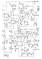
- a source 10 of electric power such as a vehicle battery or generating system with the usual voltage regulation has a grounded terminal as shown and a B+ terminal providing electric current at a predetermined voltage to an up switch 11 and a down switch 12.
- Each of the switches 11 and 12 may be described electrically as a single pole, single throw switch, but mechanically they may take a variety of forms, including two separate open-biased push button switches or a single rocking actuator biased into an open central position but actuable either way to close the separate switches. Other mechanical constructions will accur to those skilled in the art.
- the other side of the up switch 11 is connected through a resistor 14 and consecutive inverters 15, 16, which may be of the Schmitt trigger variety, to one input of a NOR gate 25, with the input of the inverter 15 connected through a capacitor .18 to ground.
- the other side of the down switch 12 is connected through a resistor 20 and consecutive inverters 21, 22 to the other input of the NOR gate 25, with the input of the inverter 2). connected through a capacitor 24 to ground.
- the output of the NOR gate 25 is provided through an inverter 26 to the clock or C input of a flip-flop 27 having grounded S input and a not-Q output connected to a data or D input and to one input of a NOR gate 28.
- the flip-flop 27 is thus connected as a toggle or divide-by-two flip-flop with the C input as the signal input and further includes an R input that is used to reset to a high not-Q output.
- the outputs of the inverters 16 and 22 are also applied to the S and R inputs, respectively, of another flip-flop 29, which has grounded C and D inputs, a not-Q output connected to the other input of the NOR gate 28 and a Q output connected to an input of a NOR gate 30.
- the other input of the NOR gate 30 receives the not-Q output of the flip-flop 27.
- the flip-flop 29 is connected as an R-S flip-flop; and the NOR gates 28, 30 both operate as AND logic circuits in the context of the overall circuit.
- the switches 11, 12 with the following R-C filter and Schmitt trigger debouncing circuitry are actuators for the window in the up and down directions, respectively.
- the NOR gate 25 is an OR logic circuit in the context of the overall circuit.
- closure of the vehicle ignition switch causes power to be applied to the circuit and the flip-flop 27 to be reset to a not-Q output.
- the latter may be assured, if desired, by the inclusion of a power-on-reset circuit described for the embodiment of Figure 2 below. It does not matter which state the flip-flop 29 is in at this point. If the up switch 11 is closed, the flip-flops 27 and 29 both have Q outputs activated high so that the output of the NOR gate 28 is high and the output of the NOR gate 30 is low.
- the NOR gate 28 provides the up driving signal to motor driving circuitry yet to be described, even if the up switch 11 is opened.
- the output of the NOR gate 28 can be sent low again without affecting the output of the NOR gate 30 by providing a high signal to input R of the flip-flop 27 or by activating either of switches 11 or 12. Any of these actions will change the state of the flip-flop 27 to turn off motor actuation by providing a high input to both of the NOR gates 28 and 30.
- the same description applies to the initial actuation of the down switch 12, except that the flip-flop 29 is originally put in a state with a high not-Q output to cause a high output from the NOR gate 30, which is the down signal to the motor driving circuitry.
- the motor 32 itself is a reversible DC motor of either permanent magnet or wound field with the former preferred.
- the armature connections only are shown and described; field connections for a wound field motor are considered well known in the art.
- the motor 32 is connected with its armature terminals in an H-switch bridge arrangement with silicon controlled rectifiers (SCR) 34, 35 and power field effect transistors (FET) 36, 37 between the B+ supply and ground, with the drain of the FET 36 connected to one armature terminal of the motor 32 and to the cathode of the SCR 34 and the drain of the FET 37 connected to the other armature terminal of the motor 32 and the cathode of the SCR 35.
- SCR silicon controlled rectifiers
- FET power field effect transistors
- the anodes/-Of the SCRs 34, 35 are both connected to the B+ supply; and the sources of the FETs 36, 37 are connected together and through a small resistance, high wattage resistor 38 to ground.
- the resistor 38 may comprise, for example, a 5.36 cm (2.11 inch) strip of copper with a width of 0.081 cm (0.032 inches) and a resistance of 0.03 ohms.
- the SCRs 34 and 35 are reverse-bypassed by diodes 40 and 41, respectively, in the normal manner for switched inductive circuits.
- An NPN bipolar transistor 44 has a collector connected to the B+ supply and an emitter connected through a diode 45 and resistor 46 (100 ohms) to the gate of the SCR 34, which gate is also connected through a resistor 47 (1 K) to the drain of the FET 36.
- an NPN bipolar transistor 48 has a collector connected to the B+ supply and an emitter connected through a diode 49 and resistor 50 to the gate of the SCR 35, which gate is connected through a resistor 51 to the drain of the FET 37.
- the base of the NPN bipolar transistor 44 and the gate of the FET 37 are both connected to the output of the NOR gate 28 to drive the motor 32 in the up direction; likewise, the base of the NPN bipolar transistor 48 and the gate of the FET 36 are both connected to the output of the NOR gate 30 to drive the motor 32 in the down direction.
- the B+ supply is connected through the series combination of a diode 53 and three resistors 54 (47 ohm), 55 (10 K) and 56 (499 ohm) to ground. Junction 57 between the resistors 54 and 55 is also connected to ground through a parallel zener diode 58 (12 volt) and capacitor 59 (22 uF) to provide a regulated voltage at the junction 57.
- the resistors 55 and 56 thus form a voltage divider which generates a reference voltage at junction 60 thereof, which is provided to the inverting input of a comparator 62.
- the non-inverting input of the comparator 62 is connected through a resistor 64 (10 K) to junction 65 of the resistor 38 and the sources of the FETs 36 and 37.
- the output of the comparator 62 is connected to the R input of the flip-flop 27.
- the comparator 62 compares the voltage dropped across the resistor 38 by the armature current of the motor 32 to the reference at the junction 60 and switches its output high when the armature current increases due to the stalling of the motor upon full travel of the window or encounter of an obstacle.
- Figure 2 shows a variation of the circuit of Figure 1 which shows how to modify it to reverse automatically if the window encounters an obstruction prior to its upper travel limit while moving upward.
- Elements 10 through 30 of Figure 1 appear in Figure 2 unchanged in form or arrangement except for the inverters 15 and 21, which become, respectively, NAND gate 15' and NOR gate 21' in Figure 2, each of NAND gate 15' and NOR gate 21' having an extra input with connection to be described below.
- the operation of this portion of the circuit of Figure 2 is the same as that of the corresponding portion of the circuit of Figure 1, except for the possibility of actuating flip-flops 27 and 29 through the additional inputs of the NAND gate 15' and the NOR gate 21', which inputs are used to produce automatic reversing in a manner to be described below.
- the elements of the motor driving and stall current sensing circuitry of Figure 2 generally correspond to those of Figure 1, with the following exceptions.
- the gates of the FETs 36 and 37 are connected to the emitters of the NPN bipolar transistors 44 and 48, respectively, rather than directly to the NOR gates 28 and 30 as in Figure 1. They are also connected to ground through resistors 70 and 71, respectively.
- Series resistor 46 and the diode 45 are reversed from the order shown in Figure 1, as are the resistor 50 and the diode 49.
- the resistors 47 and 51 of Figure 1 do not appear in Figure 2.
- the resistor 64 and the capacitor 66 are connected to the non-inverting input of the comparator 62 through a resistor 73 (1 K); and a positive feedback resistor 74 (1 M) is provided around the comparator 62. Finally, a resistor 75 (10 K) is provided between the output of the comparator 62 and the R input of the flip-flop 27.
- a limit switch 77 is provided which is normally open but closes just before the window of the vehicle reaches its fully closed position. No such limit switch is needed for the fully open position, since obstacles are not generally encountered by an opening window.
- the limit switch 77 is electrically connected between ground and the base of a PNP bipolar transistor 78 having an emitter connected through a resistor 79 (10 K) to the junction 57 and a collector connected to the junction 60. Closure of the limit switch 77 turns on the PNP bipolar transistor 78 to put the resistor 79 in parallel with the resistor 55 and thus increase the reference voltage on the junction 60.
- the circuit can be designed to sense a lower motor stall current with the limit switch 77 open, when such stall current is due to an obstruction, rather than when the limit switch 77 is closed, when such stall current is due to the travel limit of the vehicle window.
- a flip-flop 80 has a grounded S input, a D input connected through a diode 81 and the limit switch 77 to ground and also through a resistor 82 (10 K) to the not-Q output of the flip-flop 29, a not-Q output connected to the other input of the NAND gate 15' and a Q output connected to the other input of the NOR gate 21'.
- the flip-flop 80 is normally placed in a state with a high not-Q output to enable the NAND gate 15' for up motor actuation when the up switch 11 is closed; but it may be switched to the opposite state with a high Q output to initiate motor down operation through the NOR gate 21'.
- the output of the comparator 62 is connected through a parallel diode 85 and a resistor 86 (1 M) to the input of an inverter 87, which input is also connected through a capacitor 88 (0.1 pF) to ground.
- the output of the inverter 87 is connected to the C input of the flip-flop 80.
- the output of the comparator 62 also turns off the motor actuation through the R input of the flip-flop 27, but a time delay is needed to allow current to decrease to zero in the SCR 34, which has been conducting in upward window movement, before downward movement is initiated in order to prevent shorting of the power supply through the SCR 34 and the FET 36.
- the decrease of motor current causes the comparator 62 to switch its output low again; and the discharge of the capacitor 88 through the resistor 86 provides this time delay.
- junction 57 is connected through a resistor 90 (1 M) and capacitor 91 (0.1 Y F) to ground.
- Junction 92 of the resistor 90 and the capacitor 91 is connected to the input of an inverter 93 having an output connected to the R input of the flip-flop 80 and, through a diode 83, to the R input of the flip-flop 27.
- These elements provide a power-on-reset function to initially reset both the flip-flops 27 and 80 upon initial closure of the ignition switch, not shown. After this initial reset, the capacitor 91 charges, the inverter 93 switches to a low output, and these elements have no further effect upon the circuit.
- Closure of the up switch 11 initiates upward movement of the window as previously described and causes a high not-Q output from the flip-flop 29 to be applied to the D input of the flip-flop 80.
- an upward edge on the C input of the flip-flop 80 changes its output to a high Q, low not-Q state.
- the voltage at the D input of the flip-flop 80 remains high only as long as the limit switch 77 remains open. If stall current occurs in this condition of the circuit, reversal of the motor 32 will occur as previously described. Once the limit switch 77 closes, however, the voltage at the D input to the flip-flop 80 is pulled low and no motor reversal occurs with stall current.
Landscapes
- Engineering & Computer Science (AREA)
- Power Engineering (AREA)
- Window Of Vehicle (AREA)
- Power-Operated Mechanisms For Wings (AREA)
Applications Claiming Priority (2)
| Application Number | Priority Date | Filing Date | Title |
|---|---|---|---|
| US06/674,689 US4562387A (en) | 1984-11-26 | 1984-11-26 | Vehicle power window control |
| US674689 | 1984-11-26 |
Publications (1)
| Publication Number | Publication Date |
|---|---|
| EP0185449A1 true EP0185449A1 (fr) | 1986-06-25 |
Family
ID=24707554
Family Applications (1)
| Application Number | Title | Priority Date | Filing Date |
|---|---|---|---|
| EP85307776A Withdrawn EP0185449A1 (fr) | 1984-11-26 | 1985-10-28 | Appareil de commande pour un moteur d'une fenêtre d'un véhicule automobile |
Country Status (4)
| Country | Link |
|---|---|
| US (1) | US4562387A (fr) |
| EP (1) | EP0185449A1 (fr) |
| JP (1) | JPS61137984A (fr) |
| CA (1) | CA1222306A (fr) |
Cited By (3)
| Publication number | Priority date | Publication date | Assignee | Title |
|---|---|---|---|---|
| EP0275238A3 (en) * | 1987-01-15 | 1989-02-22 | Cavis Cavetti Isolati S.P.A. | Circuit arrangement for controlling the electric motors circuit arrangement for controlling the electric motors used for raising and lowering glasses in motor vehicles used for raising and lowering glasses in motor vehicles and the like and the like |
| DE9012217U1 (de) * | 1990-08-24 | 1990-10-25 | Siemens AG, 8000 München | Anordnung zum Schließen einzelner motorantreibbarer Fenster eines Fahrzeuges |
| KR20170066337A (ko) * | 2014-10-13 | 2017-06-14 | 필립모리스 프로덕츠 에스.에이. | 전기 가열식 흡연 시스템의 스위치 고장 모니터링 |
Families Citing this family (52)
| Publication number | Priority date | Publication date | Assignee | Title |
|---|---|---|---|---|
| DE3346366C2 (de) * | 1983-12-22 | 1985-12-05 | Helmut Hund KG, 6330 Wetzlar | Sicherheitsschaltung für elektromotorisch angetriebene Fensterheber für Automobile oder ähnliche Fahrzeuge |
| US4678975A (en) * | 1986-01-06 | 1987-07-07 | Ford Motor Company | Motor control circuit for motor driven power windows |
| US4683975A (en) * | 1986-09-30 | 1987-08-04 | General Motors Corporation | Vehicle power window control |
| US4710685A (en) * | 1987-02-17 | 1987-12-01 | General Motors Corporation | Vehicle power window control circuit with reverse battery protection |
| JPH0686783B2 (ja) * | 1987-03-20 | 1994-11-02 | 東進物産株式会社 | 車載用自動扉制御装置 |
| JP2549089Y2 (ja) * | 1987-10-19 | 1997-09-24 | 株式会社ミツバ | 正逆転駆動制御回路 |
| US4962337A (en) * | 1988-03-31 | 1990-10-09 | Eaton Corporation | Express window lift motor shutdown |
| US5023529A (en) * | 1988-08-05 | 1991-06-11 | Therm-O-Disc, Incorporated | Control circuit |
| US4983897A (en) * | 1988-08-05 | 1991-01-08 | Therm-O-Disc, Incorporated | Control circuit |
| US4985666A (en) * | 1988-08-30 | 1991-01-15 | Sony Corporation | Safety device for video cassette recorder |
| US4998049A (en) * | 1989-01-26 | 1991-03-05 | General Motors Corporation | Control apparatus having a remote abort function |
| FR2643172A1 (fr) * | 1989-02-13 | 1990-08-17 | Jaeger | Detecteur d'obstacle de faible encombrement |
| US4897882A (en) * | 1989-03-10 | 1990-01-30 | Caterpillar Industrial Inc. | Motor control apparatus and method |
| US4963802A (en) * | 1989-03-27 | 1990-10-16 | Elantec | Resistor programmable velocity controller |
| JPH0345098U (fr) * | 1989-09-11 | 1991-04-25 | ||
| JPH0354487U (fr) * | 1989-09-27 | 1991-05-27 | ||
| JPH03239174A (ja) * | 1990-02-16 | 1991-10-24 | Jidosha Denki Kogyo Co Ltd | ワイパ制御装置 |
| US5192901A (en) * | 1990-03-16 | 1993-03-09 | Cherry Semiconductor Corporation | Short circuit protection |
| KR930001781Y1 (ko) * | 1990-05-16 | 1993-04-15 | 석윤기 | 직류 전동기의 스위칭 회로 |
| US5723959A (en) * | 1992-08-04 | 1998-03-03 | Tokai-Rika-Denki Seishakusho Kabushiki Kaisha | Power window driving control device |
| JP2897548B2 (ja) * | 1992-09-02 | 1999-05-31 | 住友電装株式会社 | パワーウィンドウの制御装置 |
| US5471122A (en) * | 1993-09-14 | 1995-11-28 | Allegro Microsystems, Inc. | DC-motor bridge driver with end-of-braking detector |
| KR960014382B1 (ko) * | 1993-09-15 | 1996-10-15 | 삼성전자 주식회사 | 자동차의 파워 윈도우 제어 시스템 |
| DE4339553C1 (de) * | 1993-11-19 | 1995-06-22 | Sgs Thomson Microelectronics | Treiberschaltung für einen Schrittmotor |
| DE19506994C2 (de) * | 1994-02-28 | 1999-07-08 | Ohi Seisakusho Co Ltd | Verfahren zum Steuern einer Bewegung eines Fensters |
| DE4440449C2 (de) * | 1994-11-14 | 1997-06-12 | Elero Antrieb Sonnenschutz | Verfahren und Vorrichtung zur Stillstandssteuerung von elektromotorisch betriebenen Rolläden oder dergleichen |
| US5721474A (en) * | 1995-08-11 | 1998-02-24 | Samsung Electronics Co., Ltd. | Method and apparatus for preventing excessive current flow in a motor |
| US6002224A (en) * | 1996-05-29 | 1999-12-14 | Yazaki Corporation | One touch vehicle window operating circuit |
| JP3461432B2 (ja) * | 1997-07-01 | 2003-10-27 | アルプス電気株式会社 | パワーウインド装置 |
| JP3427205B2 (ja) * | 1997-08-18 | 2003-07-14 | 東洋電装株式会社 | パワーウインド装置 |
| DE69822412T2 (de) * | 1997-12-05 | 2005-03-03 | Alps Electric Co., Ltd. | Wasserdichte elektrische Fensterhebevorrichtung |
| JP4287070B2 (ja) * | 2001-04-02 | 2009-07-01 | 矢崎総業株式会社 | パワーウインド挟み込み防止装置 |
| JP2003049586A (ja) * | 2001-08-06 | 2003-02-21 | Asmo Co Ltd | 開閉体制御装置 |
| JP3779917B2 (ja) * | 2001-12-05 | 2006-05-31 | 矢崎総業株式会社 | 電界効果トランジスタ故障検出装置 |
| DE10223169B4 (de) * | 2002-05-24 | 2004-04-15 | Siemens Ag | Schaltungsanordnung zur Frequenzteilung |
| DE10224244A1 (de) * | 2002-05-29 | 2003-12-18 | Siemens Ag | Über eine Vollbrücken-Schaltung mit je Antriebs-Richtung mit unterschiedlicher Belastung betreibbare elektrische Antriebsvorrichtung |
| US6784629B2 (en) * | 2002-08-26 | 2004-08-31 | Sang J. Choi | Dual function solid state relay |
| US6756754B2 (en) | 2002-10-01 | 2004-06-29 | Siemens Vdo Automotive Inc. | Integrated one touch up and down windowlift motor with direct sense for anti-pinch |
| JP4344569B2 (ja) * | 2003-09-08 | 2009-10-14 | 矢崎総業株式会社 | パワーウインドの駆動装置 |
| DE102004007328A1 (de) * | 2004-02-14 | 2005-09-01 | Leopold Kostal Gmbh & Co Kg | Elektrische Schaltungsanordnung |
| US7633252B2 (en) * | 2005-04-14 | 2009-12-15 | Lear Corporation | Bidirectional motor stall protection circuit |
| WO2009120851A2 (fr) * | 2008-03-26 | 2009-10-01 | Enphase Energy, Inc. | Procédé et appareil pour réinitialiser des redresseurs commandés par silicium dans un pont hybride |
| US8125167B1 (en) * | 2008-10-03 | 2012-02-28 | Homerun Holdings Corporation | Motorized barrier adjustment apparatus and method |
| US8659246B2 (en) | 2010-02-23 | 2014-02-25 | Homerun Holdings Corporation | High efficiency roller shade |
| US9249623B2 (en) | 2010-02-23 | 2016-02-02 | Qmotion Incorporated | Low-power architectural covering |
| US9194179B2 (en) | 2010-02-23 | 2015-11-24 | Qmotion Incorporated | Motorized shade with the transmission wire passing through the support shaft |
| US8575872B2 (en) | 2010-02-23 | 2013-11-05 | Homerun Holdings Corporation | High efficiency roller shade and method for setting artificial stops |
| KR101470225B1 (ko) * | 2013-10-22 | 2014-12-05 | 현대자동차주식회사 | 차량용 모터 구동 장치 |
| DE102014214239A1 (de) | 2014-07-22 | 2016-01-28 | Brose Fahrzeugteile Gmbh & Co. Kg, Hallstadt | Verstellvorrichtung mit einer eine Brückenschaltung aufweisenden Steuereinheit |
| CN104533217B (zh) * | 2014-11-28 | 2017-01-25 | 埃泰克汽车电子(芜湖)有限公司 | 车窗控制电路 |
| US10315661B2 (en) | 2016-08-30 | 2019-06-11 | Ford Global Technologies, Llc | Speed-based window control |
| CN109143929B (zh) * | 2018-08-22 | 2024-04-12 | 北京丰隆科技有限公司 | 一种开窗拉幕系统控制电路及智能保护装置 |
Citations (4)
| Publication number | Priority date | Publication date | Assignee | Title |
|---|---|---|---|---|
| US4001661A (en) * | 1975-02-06 | 1977-01-04 | Toyota Jidosha Kogyo Kabushiki Kaisha | One-touch action type power window |
| GB2026723A (en) * | 1978-01-25 | 1980-02-06 | Tekron Patents Ltd | Circuits for Electric Window Winders for Vehicles |
| US4373149A (en) * | 1979-09-13 | 1983-02-08 | Regie National Des Usines Renault | Pulse-controlled electric window raiser |
| US4394605A (en) * | 1980-02-29 | 1983-07-19 | Nippondenso Co., Ltd. | Load drive control system |
Family Cites Families (12)
| Publication number | Priority date | Publication date | Assignee | Title |
|---|---|---|---|---|
| GB2013482A (en) * | 1977-11-07 | 1979-08-15 | Tanner B A | A Storage Rack |
| DE2820330C2 (de) * | 1978-05-10 | 1986-05-28 | SWF Auto-Electric GmbH, 7120 Bietigheim-Bissingen | Schaltanordnung für einen elektrischen Fensterheberantrieb oder dergleichen |
| DE2922197A1 (de) * | 1979-05-31 | 1980-12-04 | Hirschmann Radiotechnik | Selbsttaetige ueberlast-abschalteinrichtung fuer gleichstrom-motorantriebe |
| FR2460383A1 (fr) * | 1979-06-28 | 1981-01-23 | Peugeot Aciers Et Outillage | Dispositif pour la commande electrique des leve-vitres notamment d'un vehicule automobile |
| DE2926938A1 (de) * | 1979-07-04 | 1981-01-22 | Rau Swf Autozubehoer | Schaltanordnung zum antrieb eines beweglichen elementes, insbesondere zum antrieb von scheiben o.dgl. in kraftfahrzeugen |
| JPS56157289A (en) * | 1980-05-01 | 1981-12-04 | Olympus Optical Co Ltd | Braking device for motor |
| FR2484168A1 (fr) * | 1980-06-05 | 1981-12-11 | Peugeot Aciers Et Outillage | Dispositif de commande electrique de panneau ouvrant, notamment pour vehicule automobile |
| FR2499331A1 (fr) * | 1981-01-30 | 1982-08-06 | Peugeot Aciers Et Outillage | Boitier de commande pour moteur d'entrainement de panneau coulissant d'un vehicule, notamment pour leve-glace |
| US4404558A (en) * | 1981-04-15 | 1983-09-13 | Anderson Yen | Electrical control circuit for operating a garage door or similar device |
| FR2534423A1 (fr) * | 1982-10-12 | 1984-04-13 | Peugeot Aciers Et Outillage | Circuit de commande du moteur d'entrainement d'un panneau ouvrant d'un vehicule automobile |
| JPS5986498A (ja) * | 1982-11-09 | 1984-05-18 | Seiko Instr & Electronics Ltd | パルス幅変調直流サ−ボモ−タ駆動回路 |
| US4476416A (en) * | 1983-05-02 | 1984-10-09 | General Motors Corporation | Power window control for motor vehicle window |
-
1984
- 1984-11-26 US US06/674,689 patent/US4562387A/en not_active Expired - Fee Related
-
1985
- 1985-05-29 CA CA000482652A patent/CA1222306A/fr not_active Expired
- 1985-10-28 EP EP85307776A patent/EP0185449A1/fr not_active Withdrawn
- 1985-11-26 JP JP60263931A patent/JPS61137984A/ja active Pending
Patent Citations (4)
| Publication number | Priority date | Publication date | Assignee | Title |
|---|---|---|---|---|
| US4001661A (en) * | 1975-02-06 | 1977-01-04 | Toyota Jidosha Kogyo Kabushiki Kaisha | One-touch action type power window |
| GB2026723A (en) * | 1978-01-25 | 1980-02-06 | Tekron Patents Ltd | Circuits for Electric Window Winders for Vehicles |
| US4373149A (en) * | 1979-09-13 | 1983-02-08 | Regie National Des Usines Renault | Pulse-controlled electric window raiser |
| US4394605A (en) * | 1980-02-29 | 1983-07-19 | Nippondenso Co., Ltd. | Load drive control system |
Non-Patent Citations (1)
| Title |
|---|
| E.D.N. ELECTRICAL DESIGN NEWS, vol. 28, no. 19, 15th September 1983, pages 228,232,233, Boston, Massachusetts, US; R.J. VALENTINE: "FETs improve motor-drive efficiency" * |
Cited By (4)
| Publication number | Priority date | Publication date | Assignee | Title |
|---|---|---|---|---|
| EP0275238A3 (en) * | 1987-01-15 | 1989-02-22 | Cavis Cavetti Isolati S.P.A. | Circuit arrangement for controlling the electric motors circuit arrangement for controlling the electric motors used for raising and lowering glasses in motor vehicles used for raising and lowering glasses in motor vehicles and the like and the like |
| DE9012217U1 (de) * | 1990-08-24 | 1990-10-25 | Siemens AG, 8000 München | Anordnung zum Schließen einzelner motorantreibbarer Fenster eines Fahrzeuges |
| KR20170066337A (ko) * | 2014-10-13 | 2017-06-14 | 필립모리스 프로덕츠 에스.에이. | 전기 가열식 흡연 시스템의 스위치 고장 모니터링 |
| KR102496165B1 (ko) * | 2014-10-13 | 2023-02-06 | 필립모리스 프로덕츠 에스.에이. | 전기 가열식 흡연 시스템의 스위치 고장 모니터링 |
Also Published As
| Publication number | Publication date |
|---|---|
| US4562387A (en) | 1985-12-31 |
| CA1222306A (fr) | 1987-05-26 |
| JPS61137984A (ja) | 1986-06-25 |
Similar Documents
| Publication | Publication Date | Title |
|---|---|---|
| US4562387A (en) | Vehicle power window control | |
| EP0186282B1 (fr) | Appareil pour l'entraînement d'une fenêtre d'un véhicule automobile | |
| EP0124956B1 (fr) | Commande de puissance d'une fenêtre de véhicule à moteur | |
| US4678975A (en) | Motor control circuit for motor driven power windows | |
| EP0573771A1 (fr) | Dispositif de surveillance de l'état d'un contact | |
| GB2049234A (en) | Windscreen wiper installation | |
| US4710685A (en) | Vehicle power window control circuit with reverse battery protection | |
| US3651389A (en) | Safety device for use with automatic automobile window regulator | |
| US4467249A (en) | Remote automobile window control | |
| US4246526A (en) | Control circuit for a motor driven automatic valve | |
| US4104978A (en) | Protective device in a motor-operated sewing machine | |
| US4142137A (en) | Operator motor control | |
| EP0237152A1 (fr) | Commande d'entraînement de vitre avec relâchement de tension d'entraînement à bande | |
| US4972129A (en) | Passive seat belt apparatus | |
| US3708685A (en) | High inductive load energizing circuit | |
| US6876531B2 (en) | Device for detecting failure of field effect transistor | |
| US6002224A (en) | One touch vehicle window operating circuit | |
| US3379949A (en) | Electronic braking circuit for electric motor | |
| US4477758A (en) | Stepping motor overcurrent detection and protection device | |
| JPS6159068B2 (fr) | ||
| JPS5815584Y2 (ja) | 窓ガラス自動昇降制御装置 | |
| JPS6130169B2 (fr) | ||
| JPS6315504Y2 (fr) | ||
| GB2150778A (en) | Electromagnetic relay control circuits | |
| JPS6137748Y2 (fr) |
Legal Events
| Date | Code | Title | Description |
|---|---|---|---|
| PUAI | Public reference made under article 153(3) epc to a published international application that has entered the european phase |
Free format text: ORIGINAL CODE: 0009012 |
|
| 17P | Request for examination filed |
Effective date: 19851105 |
|
| AK | Designated contracting states |
Kind code of ref document: A1 Designated state(s): DE FR GB IT |
|
| 17Q | First examination report despatched |
Effective date: 19870918 |
|
| STAA | Information on the status of an ep patent application or granted ep patent |
Free format text: STATUS: THE APPLICATION IS DEEMED TO BE WITHDRAWN |
|
| 18D | Application deemed to be withdrawn |
Effective date: 19880329 |
|
| RIN1 | Information on inventor provided before grant (corrected) |
Inventor name: LEHNHOFF, RICHARD NICHOLAS |