EP0185563B1 - Verteilungsanordnung für elektrische Energie - Google Patents
Verteilungsanordnung für elektrische Energie Download PDFInfo
- Publication number
- EP0185563B1 EP0185563B1 EP85402190A EP85402190A EP0185563B1 EP 0185563 B1 EP0185563 B1 EP 0185563B1 EP 85402190 A EP85402190 A EP 85402190A EP 85402190 A EP85402190 A EP 85402190A EP 0185563 B1 EP0185563 B1 EP 0185563B1
- Authority
- EP
- European Patent Office
- Prior art keywords
- ribs
- elements
- cylindrical
- support
- conductive strips
- Prior art date
- Legal status (The legal status is an assumption and is not a legal conclusion. Google has not performed a legal analysis and makes no representation as to the accuracy of the status listed.)
- Expired - Lifetime
Links
- 239000002184 metal Substances 0.000 claims abstract description 14
- 230000002093 peripheral effect Effects 0.000 claims 1
- 238000000034 method Methods 0.000 description 2
- 229910000831 Steel Inorganic materials 0.000 description 1
- 239000011810 insulating material Substances 0.000 description 1
- 239000000463 material Substances 0.000 description 1
- 210000005036 nerve Anatomy 0.000 description 1
- 230000035515 penetration Effects 0.000 description 1
- 239000010959 steel Substances 0.000 description 1
Images



Classifications
-
- H—ELECTRICITY
- H01—ELECTRIC ELEMENTS
- H01R—ELECTRICALLY-CONDUCTIVE CONNECTIONS; STRUCTURAL ASSOCIATIONS OF A PLURALITY OF MUTUALLY-INSULATED ELECTRICAL CONNECTING ELEMENTS; COUPLING DEVICES; CURRENT COLLECTORS
- H01R25/00—Coupling parts adapted for simultaneous co-operation with two or more identical counterparts, e.g. for distributing energy to two or more circuits
- H01R25/006—Coupling parts adapted for simultaneous co-operation with two or more identical counterparts, e.g. for distributing energy to two or more circuits the coupling part being secured to apparatus or structure, e.g. duplex wall receptacle
-
- H—ELECTRICITY
- H01—ELECTRIC ELEMENTS
- H01R—ELECTRICALLY-CONDUCTIVE CONNECTIONS; STRUCTURAL ASSOCIATIONS OF A PLURALITY OF MUTUALLY-INSULATED ELECTRICAL CONNECTING ELEMENTS; COUPLING DEVICES; CURRENT COLLECTORS
- H01R13/00—Details of coupling devices of the kinds covered by groups H01R12/70 or H01R24/00 - H01R33/00
- H01R13/02—Contact members
- H01R13/15—Pins, blades or sockets having separate spring member for producing or increasing contact pressure
- H01R13/18—Pins, blades or sockets having separate spring member for producing or increasing contact pressure with the spring member surrounding the socket
Definitions
- the present application relates to an improvement of this device consisting in placing in the support not two conductive blades but cylindrical conductive pads, themselves carried by a blade.
- the device according to document EP-A 0109876 comprises a hollow profile 1, acting as a rail serving as a support for a plurality of sockets 2 of which the supply is controlled by a magneto-thermal circuit breaker 3 among others, also carried by the profile 1.
- the profile 1 is provided with end pieces 4 and fixing lugs 5.
- Said safety and / or control member 3 is not described in detail since it is a double fuse, a switch, a magneto-thermal circuit breaker or the like, it is a known material which is not part of the present invention.
- the attachment of this device 3 in the profile 1 is done, in a manner also known, by means of a piece of omega rail, placed across the profile, on the side wings of which are taken a recess and a pawl arranged on the bottom wall of said device 3.
- the modular blocks which are threaded inside the U-shaped profile consist of stacking, nesting and assembling of four elements: A, B, C, D; element A being a support for conductive strips (FIGS. 3 and 4); element B being an insulating bridge covering element A (FIGS. 5, 6, 7); element C being an earth conductive strip (FIG. 8), embedded in ribs on the upper face of trigger guard B, this strip being able to receive the earthing contact terminal according to the NF standard; the element D being a socket outlet which comes into contact on the conductive blade C, this base can be adapted to the different standards in force in the different countries.
- the elements A, B, C are stacked and fitted together, then this stack is threaded into the profile 1, then the element D is put in place and by means of a screw 7, the four elements A, B, C, D are secured to each other, this screwing also causing the assembly to be tightened on the section 1 (FIG. 9).
- the central rib 16 which separates the two grooves 8 and 9 has a blind hole 17 intended to receive the previously mentioned clamping screw 7.
- the two grooves 8 and 9 are offset by 45 ° and have at their ends tenons 18 and mortises 19; each groove comprises two vertical volumes 12a, 13a, for receiving the male plugs of a socket so that each element A comprises two pairs of vertical volumes 12a, 13a.
- Each element A thus constitutes a modular element which can be joined by tenons and mortises 18,19 to another identical element.
- the element B is constituted so as to correspond to the shape of the element A.
- This element B is a kind of plate made of insulating material intended to come on element A.
- Element B has on each of its sides a hollow shoulder 20 which is intended to be fitted into a corresponding projecting shoulder 21 formed on the two upper lateral edges of the profile 1.
- the element comprises on its upper face a groove 22 of shallow depth, delimited by two small ribs 23 and 24.
- This groove 22 is intended to receive the conductive strip C which will be described below -after and which is indicated in dotted lines in FIG. 5.
- the trigger guard B has hollow cylindrical projections of revolution 25 and 26. These hollow cylindrical projections 25 and 26 are intended to allow passage to the plugs of an electrical outlet. At locations corresponding to those of the blind holes 17 of the element A, the trigger guard B is crossed by orifices 27 intended to give passage to the clamping screw 7. There is therefore an orifice 27 between each pair of projections 25 and 26.
- a blind hole 28 of shallow depth is placed in the groove 22 at the location which the earth terminal must occupy according to the NF standard with respect to the two holes of the contact plugs which must pass through the hollow cylindrical projections 25 and 26. The purpose of this blind hole 28 is to leave room for the fastening rivet of the earth terminal.
- each element B having the same dimensions as an element A constitutes with the latter a modular element.
- an element B placed on an element A.
- a correct position of the element B is obtained on the element A before tightening.
- the earth conductive strip, which constitutes the element C is shown in Figures 8 and 9.
- This strip has a thickness slightly less than the depth of the groove 22. It has at regular intervals notches 32 intended to allow passage to the cylindrical projections 25, notches 33 intended for the projections 26, orifices 34 intended to receive the base of the earth terminals and orifices 37 which correspond to the orifices 27 of the elements B and to the blind holes 17 of the elements A.
- the correct positioning of the element C on the element B is made by pressing the notches 32 and 33 against the edges of the projections 25 and 26.
- the rivet heads used for fixing the plugs 39 in the orifices 34 are housed in the blind holes 28 described above.
- This strip 47 makes it possible to provide a volume 48 with an undercut, somewhat similar to a mortise intended to make it possible to fix the profile 1 to a wall or a cabinet wall by the usual method of countersunk head nut; but if this method of attachment is not necessary, the strip 47 can be an integral part of the bottom 49 of the profile, shown in dotted lines.
- the assembly is then firmly held in place by tightening on the profile 1.
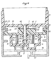
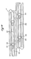
- FIGS. 10, 11 and 12 represent the improvement to the device previously described in relation to FIGS. 1 to 9.
- the support A has two pairs of longitudinal ribs 101 and 102 which have at regular intervals bosses 103 for the ribs 101 and 104 for the ribs 102.
- These bosses 103 and 104 define housings cylindrical hollows in which metal studs 105, hollow, and cylindrical, fit together, the internal diameter of which is very slightly greater than the external diameter of the plugs.
- each stud 105 is pierced with a lateral opening 107 in which a metal ball 108 partially protruded pushed by a spring 109, placed in a tube cylindrical 110 fixed against the stud 105, the axis of the cylindrical tube 110 being perpendicular to that of the metallic stud 105.
- the cylindrical tube 110 has an outside diameter less than the distance separating two nerves vures 101 (or 102) so as to fit into the respective groove defined by each pair of respective ribs (101, resp. 102).
- the metal ball 108 exerts, by means of the spring 109, a constant pressure on said plug which ensures an electrical contact of excellent quality and practically eliminates all false contacts, which is very important when the device is used to power a set of measuring devices or a set of electronic devices such as television monitors.
- FIG. 12 represents an alternative embodiment of FIG. 11, in which the spring 109 is replaced by an elastic belt 111, made of steel for example, which, similar to a circlip, is engaged in a groove 112 hollowed out in the periphery of the metal stud 105.
- This belt 111 includes a boss 113 for holding the metal ball 108.
Landscapes
- Coupling Device And Connection With Printed Circuit (AREA)
- Electrical Discharge Machining, Electrochemical Machining, And Combined Machining (AREA)
- Fixed Capacitors And Capacitor Manufacturing Machines (AREA)
- Inorganic Insulating Materials (AREA)
- Springs (AREA)
- Thermistors And Varistors (AREA)
- Connector Housings Or Holding Contact Members (AREA)
- Details Of Connecting Devices For Male And Female Coupling (AREA)
Claims (7)
Priority Applications (1)
| Application Number | Priority Date | Filing Date | Title |
|---|---|---|---|
| AT85402190T ATE50089T1 (de) | 1984-11-14 | 1985-11-13 | Verteilungsanordnung fuer elektrische energie. |
Applications Claiming Priority (2)
| Application Number | Priority Date | Filing Date | Title |
|---|---|---|---|
| FR8417369A FR2573274B2 (fr) | 1984-11-14 | 1984-11-14 | Dispositif modulaire de distribution d'energie electrique |
| FR8417369 | 1984-11-14 |
Publications (2)
| Publication Number | Publication Date |
|---|---|
| EP0185563A1 EP0185563A1 (de) | 1986-06-25 |
| EP0185563B1 true EP0185563B1 (de) | 1990-01-31 |
Family
ID=9309590
Family Applications (1)
| Application Number | Title | Priority Date | Filing Date |
|---|---|---|---|
| EP85402190A Expired - Lifetime EP0185563B1 (de) | 1984-11-14 | 1985-11-13 | Verteilungsanordnung für elektrische Energie |
Country Status (4)
| Country | Link |
|---|---|
| EP (1) | EP0185563B1 (de) |
| AT (1) | ATE50089T1 (de) |
| DE (1) | DE3575820D1 (de) |
| FR (1) | FR2573274B2 (de) |
Families Citing this family (2)
| Publication number | Priority date | Publication date | Assignee | Title |
|---|---|---|---|---|
| FR2638313A1 (fr) * | 1988-10-24 | 1990-04-27 | Bahier Francis | Tiroir de prises de courant pour armoire electronique normalisee |
| US10524377B2 (en) | 2018-01-31 | 2019-12-31 | Eaton Intelligent Power Limited | Power distribution unit with interior busbars |
Family Cites Families (9)
| Publication number | Priority date | Publication date | Assignee | Title |
|---|---|---|---|---|
| US1481278A (en) * | 1919-12-23 | 1924-01-22 | Chas Cory & Son Inc | Multiple-socket receptacle strip |
| GB262907A (en) * | 1925-11-19 | 1926-12-23 | Robert Franklin Baerman | Improvements in sockets for holding electric lamps or the like |
| US1965181A (en) * | 1928-06-15 | 1934-07-03 | Carl A Gerlach | System of electrical distribution |
| US2143131A (en) * | 1936-05-26 | 1939-01-10 | Henry E Piltz | Electrical connecter |
| BE468105A (de) * | 1945-09-21 | |||
| FR1010446A (fr) * | 1948-08-18 | 1952-06-11 | Alvéole rigide à serrage élastique pour organes de connexion électrique | |
| FR1412563A (fr) * | 1964-08-21 | 1965-10-01 | Cie Generale Entpr Elec | Dispositif de raccordement électrique |
| DE3023341A1 (de) * | 1980-06-21 | 1982-01-14 | Daimler-Benz Ag, 7000 Stuttgart | Stromleiter, insbesondere isolierter stromleiter fuer grossraumfahrzeuge |
| DE3370906D1 (en) * | 1982-10-26 | 1987-05-14 | Professional General Elect | Modular device for the distribution of electrical energy |
-
1984
- 1984-11-14 FR FR8417369A patent/FR2573274B2/fr not_active Expired
-
1985
- 1985-11-13 DE DE8585402190T patent/DE3575820D1/de not_active Expired - Lifetime
- 1985-11-13 AT AT85402190T patent/ATE50089T1/de not_active IP Right Cessation
- 1985-11-13 EP EP85402190A patent/EP0185563B1/de not_active Expired - Lifetime
Also Published As
| Publication number | Publication date |
|---|---|
| DE3575820D1 (de) | 1990-03-08 |
| FR2573274B2 (fr) | 1987-01-23 |
| ATE50089T1 (de) | 1990-02-15 |
| EP0185563A1 (de) | 1986-06-25 |
| FR2573274A2 (fr) | 1986-05-16 |
Similar Documents
| Publication | Publication Date | Title |
|---|---|---|
| FR3036857A1 (fr) | Clip metallique de connexion electrique d'un fil conducteur a un element metallique | |
| EP2564450B1 (de) | Akkumulatoranordnung für eine batterie eines elektro- oder hybridfahrzeuges mit verformbarer verbinderstütze | |
| EP0109876B1 (de) | Modulartige Verteilungsanordnung für elektrische Energie | |
| EP1714161B1 (de) | Hilfselement zum fixieren eines stromsensors an einem elektrischen leiter | |
| EP2859631B1 (de) | Endmaskenplatte mit zentrierungsmitteln für ein innenelement von einem elektrischen apparat | |
| FR2578361A1 (fr) | Distributeur electrique de forme modulaire, destine en particulier aux applications aeronautiques et aerospatiales | |
| EP3583825A1 (de) | Elektrische verbindungsschnittstelle einer elektrischen heizvorrichtung für ein kraftfahrzeug | |
| EP3707779B1 (de) | Elektrische verbindungsvorrichtung für ein elektrisches gerät und verbindungsverfahren mit dieser vorrichtung | |
| FR2926930A1 (fr) | Socle d'appareil electrique et ensembles le comportant | |
| EP0375654B1 (de) | Zusammenbau einer Stecklampenfassung und einer Lichtleiste | |
| FR2529033A1 (de) | ||
| EP1934996B1 (de) | Elektrisches schaltgerät mit schmelzsicherung | |
| CA2286416C (fr) | Montage de resistance de fermeture pour appareillage electrique a haute tension | |
| FR2535144A1 (fr) | Dispositif modulaire de distribution d'energie electrique | |
| EP0076183B1 (de) | Elektrische Verteilungsvorrichtung | |
| EP0259199B1 (de) | Elektrische Verbindungsanordnung für einen Lautsprechermotor | |
| WO2006048530A1 (fr) | Element de bornier et connecteur sans vis | |
| EP0172779B1 (de) | Mehrpoliger elektrischer Verbinder | |
| FR2917906A1 (fr) | Connecteur multicontacts. | |
| FR2634097A1 (fr) | Boitier pour le logement etanche en particulier de composants electriques ou electroniques | |
| FR2860346A1 (fr) | Appareil electrique comportant un boitier isolant et une borne a connexion automatique disposee dans ledit boitier | |
| FR2597269A1 (fr) | Connecteur electrique, notamment pour plot de batterie et procede de fabrication d'un tel connecteur | |
| FR2931590A1 (fr) | Mecanisme d'appareillage de prise de courant comportant une borne de connexion electrique d'accueil d'une broche plate de fiche electrique | |
| FR2811812A1 (fr) | Connecteur de raccordement et ensemble de raccordement electrique entre un jeu de barres et au moins un cable conducteur | |
| FR2547694A2 (fr) | Dispositif modulaire de distribution d'energie electrique |
Legal Events
| Date | Code | Title | Description |
|---|---|---|---|
| PUAI | Public reference made under article 153(3) epc to a published international application that has entered the european phase |
Free format text: ORIGINAL CODE: 0009012 |
|
| AK | Designated contracting states |
Kind code of ref document: A1 Designated state(s): AT BE CH DE GB IT LI NL SE |
|
| 17P | Request for examination filed |
Effective date: 19861229 |
|
| 17Q | First examination report despatched |
Effective date: 19880622 |
|
| GRAA | (expected) grant |
Free format text: ORIGINAL CODE: 0009210 |
|
| AK | Designated contracting states |
Kind code of ref document: B1 Designated state(s): AT BE CH DE GB IT LI NL SE |
|
| REF | Corresponds to: |
Ref document number: 50089 Country of ref document: AT Date of ref document: 19900215 Kind code of ref document: T |
|
| GBT | Gb: translation of ep patent filed (gb section 77(6)(a)/1977) | ||
| REF | Corresponds to: |
Ref document number: 3575820 Country of ref document: DE Date of ref document: 19900308 |
|
| ITF | It: translation for a ep patent filed | ||
| PLBE | No opposition filed within time limit |
Free format text: ORIGINAL CODE: 0009261 |
|
| STAA | Information on the status of an ep patent application or granted ep patent |
Free format text: STATUS: NO OPPOSITION FILED WITHIN TIME LIMIT |
|
| 26N | No opposition filed | ||
| ITTA | It: last paid annual fee | ||
| EAL | Se: european patent in force in sweden |
Ref document number: 85402190.4 |
|
| PGFP | Annual fee paid to national office [announced via postgrant information from national office to epo] |
Ref country code: SE Payment date: 20011116 Year of fee payment: 17 |
|
| PGFP | Annual fee paid to national office [announced via postgrant information from national office to epo] |
Ref country code: NL Payment date: 20011123 Year of fee payment: 17 |
|
| PGFP | Annual fee paid to national office [announced via postgrant information from national office to epo] |
Ref country code: AT Payment date: 20011129 Year of fee payment: 17 |
|
| REG | Reference to a national code |
Ref country code: GB Ref legal event code: IF02 |
|
| PG25 | Lapsed in a contracting state [announced via postgrant information from national office to epo] |
Ref country code: AT Free format text: LAPSE BECAUSE OF NON-PAYMENT OF DUE FEES Effective date: 20021113 |
|
| PG25 | Lapsed in a contracting state [announced via postgrant information from national office to epo] |
Ref country code: SE Free format text: LAPSE BECAUSE OF NON-PAYMENT OF DUE FEES Effective date: 20021114 |
|
| PG25 | Lapsed in a contracting state [announced via postgrant information from national office to epo] |
Ref country code: NL Free format text: LAPSE BECAUSE OF NON-PAYMENT OF DUE FEES Effective date: 20030601 |
|
| EUG | Se: european patent has lapsed | ||
| NLV4 | Nl: lapsed or anulled due to non-payment of the annual fee |
Effective date: 20030601 |
|
| PGFP | Annual fee paid to national office [announced via postgrant information from national office to epo] |
Ref country code: GB Payment date: 20031119 Year of fee payment: 19 |
|
| PGFP | Annual fee paid to national office [announced via postgrant information from national office to epo] |
Ref country code: BE Payment date: 20031218 Year of fee payment: 19 |
|
| PGFP | Annual fee paid to national office [announced via postgrant information from national office to epo] |
Ref country code: CH Payment date: 20040226 Year of fee payment: 19 |
|
| PG25 | Lapsed in a contracting state [announced via postgrant information from national office to epo] |
Ref country code: GB Free format text: LAPSE BECAUSE OF NON-PAYMENT OF DUE FEES Effective date: 20041113 |
|
| PG25 | Lapsed in a contracting state [announced via postgrant information from national office to epo] |
Ref country code: LI Free format text: LAPSE BECAUSE OF NON-PAYMENT OF DUE FEES Effective date: 20041130 Ref country code: CH Free format text: LAPSE BECAUSE OF NON-PAYMENT OF DUE FEES Effective date: 20041130 Ref country code: BE Free format text: LAPSE BECAUSE OF NON-PAYMENT OF DUE FEES Effective date: 20041130 |
|
| PGFP | Annual fee paid to national office [announced via postgrant information from national office to epo] |
Ref country code: DE Payment date: 20041231 Year of fee payment: 20 |
|
| BERE | Be: lapsed |
Owner name: S.A. *PGEP PROFESSIONAL GENERAL ELECTRONIC PRODUCT Effective date: 20041130 |
|
| GBPC | Gb: european patent ceased through non-payment of renewal fee |
Effective date: 20041113 |
|
| REG | Reference to a national code |
Ref country code: CH Ref legal event code: PL |
|
| BERE | Be: lapsed |
Owner name: S.A. *PGEP PROFESSIONAL GENERAL ELECTRONIC PRODUCT Effective date: 20041130 |