EP0185566A1 - Lötmaschine - Google Patents
Lötmaschine Download PDFInfo
- Publication number
- EP0185566A1 EP0185566A1 EP85402212A EP85402212A EP0185566A1 EP 0185566 A1 EP0185566 A1 EP 0185566A1 EP 85402212 A EP85402212 A EP 85402212A EP 85402212 A EP85402212 A EP 85402212A EP 0185566 A1 EP0185566 A1 EP 0185566A1
- Authority
- EP
- European Patent Office
- Prior art keywords
- path
- machine according
- solder pot
- frame
- pot
- Prior art date
- Legal status (The legal status is an assumption and is not a legal conclusion. Google has not performed a legal analysis and makes no representation as to the accuracy of the status listed.)
- Granted
Links
Images


Classifications
-
- B—PERFORMING OPERATIONS; TRANSPORTING
- B23—MACHINE TOOLS; METAL-WORKING NOT OTHERWISE PROVIDED FOR
- B23K—SOLDERING OR UNSOLDERING; WELDING; CLADDING OR PLATING BY SOLDERING OR WELDING; CUTTING BY APPLYING HEAT LOCALLY, e.g. FLAME CUTTING; WORKING BY LASER BEAM
- B23K3/00—Tools, devices or special appurtenances for soldering, e.g. brazing, or unsoldering, not specially adapted for particular methods
- B23K3/06—Solder feeding devices; Solder melting pans
- B23K3/0646—Solder baths
- B23K3/0669—Solder baths with dipping means
- B23K3/0676—Conveyors therefor
Definitions
- the cards are driven on a conveyor in horizontal displacement or in slightly ascending or descending slope and come to lick during this displacement the top of a wave of molten solder alloy created by a nozzle.
- these welding machines also include a flux distributor and a preheating unit, which must both be subject to precise vertical adjustment relative to the cards moving on the conveyor.
- the present invention provides a wave welding machine comprising a frame, at least one solder pot mounted on said frame and comprising a nozzle intended to produce said wave, a conveyor mounted on said frame and intended to drive printed circuit boards along a substantially linear path, and a device for adjusting the height of said solder pot, so as to allow the height adjustment of said wave relative to said path, characterized in that said frame comprises a displacement path, of the same general orientation as said conveyor, on which is mounted said solder pot, said path and said path forming between them a predetermined angle of low value and said path having as small an inclination as possible with respect to the 'horizontal, and a device for adjusting the position of said solder pot along said displacement path.
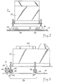
- the welding machine 10 illustrated in FIG. 1 comprises a frame 12, of elongated shape, on the upper face of which is fixed a sheet 14 defining an installation plan.
- the machine also comprises a conveyor 26, arranged above the devices mentioned above and intended to drive printed circuit boards (not shown) arranged flat, following a straight rectilinear path, or with a slightly upward or downward slope.
- Each printed circuit board is placed on the conveyor in such a way that its face on which the welds are to be made is oriented downwards, and the path of the cards on the conveyor ensures the passage of their lower faces successively opposite the dispenser. flux, of the preheating assembly then of the solder pot, so that the underside of the card is licked by the solder wave created by the nozzle of the solder pot.
- the conveyor 26 is on a slightly rising slope and the installation plane 14, -this the path of movement 28- is horizontal. In this way, when the solder pot is moved along the travel path, the relative vertical distance between the solder pot nozzle and the conveyor is varied, and this variation can be controlled extremely precisely and reliably despite the high weight of the solder pot since the force required to move the solder pot along the travel path is very low.
- the advantage of providing that only one of the tracks consists of a rail is that one can do without adjusting the spacing between the bearings 38 and / or the tracks 30, 32.
- the solder pot may be mounted on its path of travel by means of slides, preferably lined with material with a low coefficient of friction, for example PTFE ( polytetrafluoroethylene).
- the bearings are produced in the form of cages and / or ball shoes.
- the machine comprises a device 41 for adjusting the position of the solder pot along its path of movement.
- This device of the type commonly called screw-nut, comprises a screw 42 rotatably mounted on the solder pot but without the possibility of moving longitudinally relative to the latter, and a nut 44 fixedly mounted on the sheet 14, 'preferably in a ball joint or via a universal joint so as to allow mutual alignment of the screw and the nut.
- the rotation of the screw causes its displacement relative to the nut and therefore the displacement of the solder pot relative to its path of movement.
- the reduction provided by the screw-nut cooperation makes it possible to very precisely adjust the position of the solder pot. It also makes it possible to motorize the adjustment device, by means of a low power motor 46 whose shaft is directly coupled to the screw 42.
- Another advantage lies in the non-reversibility of this adjustment device which provides a reliable brake and stop for the solder pot.
- the flow distributor and / or the preheating assembly are also mounted on the movement path 28.
Landscapes
- Engineering & Computer Science (AREA)
- Mechanical Engineering (AREA)
- Electric Connection Of Electric Components To Printed Circuits (AREA)
- Molten Solder (AREA)
- Die Bonding (AREA)
- Nonmetallic Welding Materials (AREA)
Priority Applications (1)
| Application Number | Priority Date | Filing Date | Title |
|---|---|---|---|
| AT85402212T ATE44254T1 (de) | 1984-11-15 | 1985-11-15 | Loetmaschine. |
Applications Claiming Priority (2)
| Application Number | Priority Date | Filing Date | Title |
|---|---|---|---|
| FR8417451A FR2572972B1 (fr) | 1984-11-15 | 1984-11-15 | Machine de soudage. |
| FR8417451 | 1984-11-15 |
Publications (2)
| Publication Number | Publication Date |
|---|---|
| EP0185566A1 true EP0185566A1 (de) | 1986-06-25 |
| EP0185566B1 EP0185566B1 (de) | 1989-06-28 |
Family
ID=9309631
Family Applications (1)
| Application Number | Title | Priority Date | Filing Date |
|---|---|---|---|
| EP85402212A Expired EP0185566B1 (de) | 1984-11-15 | 1985-11-15 | Lötmaschine |
Country Status (7)
| Country | Link |
|---|---|
| US (1) | US4616775A (de) |
| EP (1) | EP0185566B1 (de) |
| JP (1) | JPS61126963A (de) |
| AT (1) | ATE44254T1 (de) |
| CA (1) | CA1271669A (de) |
| DE (2) | DE3571216D1 (de) |
| FR (1) | FR2572972B1 (de) |
Families Citing this family (10)
| Publication number | Priority date | Publication date | Assignee | Title |
|---|---|---|---|---|
| US5439158A (en) * | 1994-02-22 | 1995-08-08 | Sund; William | Atmosphere controlled soldering apparatus with incorporated solder pump |
| JP3740041B2 (ja) * | 2001-08-31 | 2006-01-25 | 千住金属工業株式会社 | プリント基板の部分はんだ付け方法 |
| US6581818B1 (en) * | 2001-12-27 | 2003-06-24 | Yu-Chen Tu | Trough device in a soldering furnace |
| GB0411573D0 (en) * | 2004-05-24 | 2004-06-23 | Pillarhouse Int Ltd | Selective soldering apparatus |
| US7392926B2 (en) * | 2004-09-15 | 2008-07-01 | Hakko Corporation | Electrically-controlled soldering pot apparatus |
| DE102014110720B4 (de) * | 2014-07-29 | 2025-12-31 | Illinois Tool Works Inc. | Lötmodul |
| CN104759729A (zh) * | 2015-04-14 | 2015-07-08 | 李理 | 一种电磁熔锡炉锡块运送滑轨 |
| CN108581118B (zh) * | 2017-03-17 | 2022-01-11 | 泰科电子(上海)有限公司 | 焊膏自动供应系统 |
| US12214447B2 (en) * | 2017-11-28 | 2025-02-04 | Nordson Corporation | Synchronous motion selective soldering apparatus and method |
| CN112276287A (zh) * | 2020-09-10 | 2021-01-29 | 渠广波 | 一种pcb板回流焊设备传输机构 |
Citations (2)
| Publication number | Priority date | Publication date | Assignee | Title |
|---|---|---|---|---|
| FR2502525A1 (fr) * | 1981-03-25 | 1982-10-01 | Zevatron Gmbh Fertigungseinric | Procede et appareil pour le soudage de pieces a la machine, en particulier de plaquettes de circuits imprimes |
| EP0118091A1 (de) * | 1983-02-28 | 1984-09-12 | Electrovert Ltd. | Automatische Lötwellenmaschine |
Family Cites Families (3)
| Publication number | Priority date | Publication date | Assignee | Title |
|---|---|---|---|---|
| GB1102621A (en) * | 1965-04-07 | 1968-02-07 | Electrovert Mfg Company Ltd | Method and apparatus for fluxing and soldering connections on printed circuit boards |
| JPS58209471A (ja) * | 1982-05-31 | 1983-12-06 | Nippon Radiator Co Ltd | 自動半田付け装置 |
| JPS5976660A (ja) * | 1982-10-25 | 1984-05-01 | Tamura Seisakusho Co Ltd | はんだ付け装置 |
-
1984
- 1984-11-15 FR FR8417451A patent/FR2572972B1/fr not_active Expired
-
1985
- 1985-11-14 US US06/798,170 patent/US4616775A/en not_active Expired - Fee Related
- 1985-11-14 CA CA000495280A patent/CA1271669A/fr not_active Expired - Fee Related
- 1985-11-15 DE DE8585402212T patent/DE3571216D1/de not_active Expired
- 1985-11-15 JP JP60256509A patent/JPS61126963A/ja active Pending
- 1985-11-15 EP EP85402212A patent/EP0185566B1/de not_active Expired
- 1985-11-15 AT AT85402212T patent/ATE44254T1/de not_active IP Right Cessation
- 1985-11-15 DE DE198585402212T patent/DE185566T1/de active Pending
Patent Citations (2)
| Publication number | Priority date | Publication date | Assignee | Title |
|---|---|---|---|---|
| FR2502525A1 (fr) * | 1981-03-25 | 1982-10-01 | Zevatron Gmbh Fertigungseinric | Procede et appareil pour le soudage de pieces a la machine, en particulier de plaquettes de circuits imprimes |
| EP0118091A1 (de) * | 1983-02-28 | 1984-09-12 | Electrovert Ltd. | Automatische Lötwellenmaschine |
Also Published As
| Publication number | Publication date |
|---|---|
| EP0185566B1 (de) | 1989-06-28 |
| JPS61126963A (ja) | 1986-06-14 |
| ATE44254T1 (de) | 1989-07-15 |
| CA1271669A (fr) | 1990-07-17 |
| DE185566T1 (de) | 1987-04-09 |
| FR2572972A1 (fr) | 1986-05-16 |
| DE3571216D1 (en) | 1989-08-03 |
| FR2572972B1 (fr) | 1987-02-13 |
| US4616775A (en) | 1986-10-14 |
Similar Documents
| Publication | Publication Date | Title |
|---|---|---|
| EP0185566B1 (de) | Lötmaschine | |
| EP0367670B1 (de) | Vorrichtung zur Einstellung von Glastafeln | |
| FR2547756A1 (fr) | Procede et installation de soudage par point a faisceau laser | |
| FR2608955A1 (fr) | Appareil et procede pour fabriquer des poutres a ame pleine | |
| EP0186538A2 (de) | Wellenlötmaschine | |
| CN1070306A (zh) | 用于检测焊料波形面的装置 | |
| KR830007365A (ko) | 깊이가 각각 다른 박스에 물품층을 선택적으로 패킹하는 장치 | |
| FR2510082A1 (fr) | Appareil a alimenter des grilles mobiles en boulettes vertes | |
| FR2634416A1 (fr) | Assemblage oscillant a fil metallique de soudage pour thermosoudage d'un film thermoplastique et machine a empaqueter horizontale pour empaqueter des objets dans un film thermoplastique comportant un tel assemblage oscillant | |
| DE68915526T2 (de) | Ein automatisches Lötverfahren und Apparat dafür. | |
| US6717111B2 (en) | Grilling component | |
| KR960007162B1 (ko) | 플랜지 용접장치 | |
| FR2572971A1 (fr) | Machine de soudage. | |
| EP0187555A1 (de) | Wellenlötmaschine | |
| EP1885633B1 (de) | Pilgerförderer mit verringerter wärmeleitung | |
| EP0278885A1 (de) | Vorrichtung zum Löten von gedruckten Schaltungen auf einen Träger | |
| CA2153772C (fr) | Procede et installation de fabrication de rubans metalliques amorphes par hypertrempe | |
| FR2486725A1 (fr) | Procede et appareil de presoudage de billes de soudure sur des pattes de connexion | |
| JPS5976660A (ja) | はんだ付け装置 | |
| FR2661351A1 (fr) | Machine et installation de decoupe de produits en plaque, notamment pour la realisation de canapes. | |
| EP3774610A1 (de) | Verbesserte förderanordnung | |
| FR2545398A1 (fr) | Installation pour l'assemblage et/ou l'usinage de pieces portees par des palettes circulantes et immobilisables | |
| EP0812663A1 (de) | Schlitz- und Schneidmaschine für Schaumstoffplatten | |
| CA1228174A (en) | Wave soldering machine | |
| FR2512723A1 (fr) | Installation pour l'assemblage et/ou l'usinage de pieces portees par des palettes circulantes et immobilisables |
Legal Events
| Date | Code | Title | Description |
|---|---|---|---|
| PUAI | Public reference made under article 153(3) epc to a published international application that has entered the european phase |
Free format text: ORIGINAL CODE: 0009012 |
|
| AK | Designated contracting states |
Kind code of ref document: A1 Designated state(s): AT BE CH DE GB IT LI LU NL SE |
|
| ITCL | It: translation for ep claims filed |
Representative=s name: JACOBACCI CASETTA & PERANI S.P.A. |
|
| 17P | Request for examination filed |
Effective date: 19861208 |
|
| TCAT | At: translation of patent claims filed | ||
| TCNL | Nl: translation of patent claims filed | ||
| DET | De: translation of patent claims | ||
| 17Q | First examination report despatched |
Effective date: 19880810 |
|
| GRAA | (expected) grant |
Free format text: ORIGINAL CODE: 0009210 |
|
| AK | Designated contracting states |
Kind code of ref document: B1 Designated state(s): AT BE CH DE GB IT LI LU NL SE |
|
| REF | Corresponds to: |
Ref document number: 44254 Country of ref document: AT Date of ref document: 19890715 Kind code of ref document: T |
|
| REF | Corresponds to: |
Ref document number: 3571216 Country of ref document: DE Date of ref document: 19890803 |
|
| GBT | Gb: translation of ep patent filed (gb section 77(6)(a)/1977) | ||
| ITF | It: translation for a ep patent filed | ||
| PGFP | Annual fee paid to national office [announced via postgrant information from national office to epo] |
Ref country code: AT Payment date: 19891020 Year of fee payment: 5 |
|
| PGFP | Annual fee paid to national office [announced via postgrant information from national office to epo] |
Ref country code: GB Payment date: 19891130 Year of fee payment: 5 |
|
| PLBE | No opposition filed within time limit |
Free format text: ORIGINAL CODE: 0009261 |
|
| STAA | Information on the status of an ep patent application or granted ep patent |
Free format text: STATUS: NO OPPOSITION FILED WITHIN TIME LIMIT |
|
| 26N | No opposition filed | ||
| PG25 | Lapsed in a contracting state [announced via postgrant information from national office to epo] |
Ref country code: GB Effective date: 19901115 Ref country code: AT Effective date: 19901115 |
|
| BERE | Be: lapsed |
Owner name: S.A. OUTILLAGES SCIENTIFIQUES ET DE LABORATOIRES Effective date: 19901130 |
|
| GBPC | Gb: european patent ceased through non-payment of renewal fee | ||
| PGFP | Annual fee paid to national office [announced via postgrant information from national office to epo] |
Ref country code: LU Payment date: 19911118 Year of fee payment: 7 Ref country code: CH Payment date: 19911118 Year of fee payment: 7 |
|
| PGFP | Annual fee paid to national office [announced via postgrant information from national office to epo] |
Ref country code: DE Payment date: 19911122 Year of fee payment: 7 |
|
| PGFP | Annual fee paid to national office [announced via postgrant information from national office to epo] |
Ref country code: SE Payment date: 19911125 Year of fee payment: 7 |
|
| ITTA | It: last paid annual fee | ||
| PGFP | Annual fee paid to national office [announced via postgrant information from national office to epo] |
Ref country code: NL Payment date: 19911130 Year of fee payment: 7 |
|
| PGFP | Annual fee paid to national office [announced via postgrant information from national office to epo] |
Ref country code: BE Payment date: 19911217 Year of fee payment: 7 |
|
| EPTA | Lu: last paid annual fee | ||
| PG25 | Lapsed in a contracting state [announced via postgrant information from national office to epo] |
Ref country code: LU Free format text: LAPSE BECAUSE OF NON-PAYMENT OF DUE FEES Effective date: 19921115 |
|
| PG25 | Lapsed in a contracting state [announced via postgrant information from national office to epo] |
Ref country code: SE Effective date: 19921116 |
|
| PG25 | Lapsed in a contracting state [announced via postgrant information from national office to epo] |
Ref country code: LI Effective date: 19921130 Ref country code: CH Effective date: 19921130 Ref country code: BE Effective date: 19921130 |
|
| BERE | Be: lapsed |
Owner name: S.A. OUTILLAGES SCIENTIFIQUES ET DE LABORATOIRES Effective date: 19921130 |
|
| PG25 | Lapsed in a contracting state [announced via postgrant information from national office to epo] |
Ref country code: NL Effective date: 19930601 |
|
| NLV4 | Nl: lapsed or anulled due to non-payment of the annual fee | ||
| REG | Reference to a national code |
Ref country code: CH Ref legal event code: PL |
|
| PG25 | Lapsed in a contracting state [announced via postgrant information from national office to epo] |
Ref country code: DE Effective date: 19930803 |
|
| EUG | Se: european patent has lapsed |
Ref document number: 85402212.6 Effective date: 19930610 |