EP0185571A1 - Sektorenbedüsungseinrichtung bei der Kohlengewinnung - Google Patents
Sektorenbedüsungseinrichtung bei der Kohlengewinnung Download PDFInfo
- Publication number
- EP0185571A1 EP0185571A1 EP85402237A EP85402237A EP0185571A1 EP 0185571 A1 EP0185571 A1 EP 0185571A1 EP 85402237 A EP85402237 A EP 85402237A EP 85402237 A EP85402237 A EP 85402237A EP 0185571 A1 EP0185571 A1 EP 0185571A1
- Authority
- EP
- European Patent Office
- Prior art keywords
- drum
- peaks
- disc
- cylindrical
- channels
- Prior art date
- Legal status (The legal status is an assumption and is not a legal conclusion. Google has not performed a legal analysis and makes no representation as to the accuracy of the status listed.)
- Granted
Links
- 239000003245 coal Substances 0.000 title description 7
- 238000005065 mining Methods 0.000 title description 3
- 238000005507 spraying Methods 0.000 title 1
- XLYOFNOQVPJJNP-UHFFFAOYSA-N water Substances O XLYOFNOQVPJJNP-UHFFFAOYSA-N 0.000 claims abstract description 17
- 241001417494 Sciaenidae Species 0.000 description 4
- OKTJSMMVPCPJKN-UHFFFAOYSA-N Carbon Chemical compound [C] OKTJSMMVPCPJKN-UHFFFAOYSA-N 0.000 description 1
- 229910052799 carbon Inorganic materials 0.000 description 1
- 239000000428 dust Substances 0.000 description 1
- 238000004880 explosion Methods 0.000 description 1
- 230000012447 hatching Effects 0.000 description 1
- JEIPFZHSYJVQDO-UHFFFAOYSA-N iron(III) oxide Inorganic materials O=[Fe]O[Fe]=O JEIPFZHSYJVQDO-UHFFFAOYSA-N 0.000 description 1
- 238000004519 manufacturing process Methods 0.000 description 1
- 238000003307 slaughter Methods 0.000 description 1
- 239000007787 solid Substances 0.000 description 1
- 239000007921 spray Substances 0.000 description 1
- 239000008400 supply water Substances 0.000 description 1
Images




Classifications
-
- E—FIXED CONSTRUCTIONS
- E21—EARTH OR ROCK DRILLING; MINING
- E21C—MINING OR QUARRYING
- E21C35/00—Details of, or accessories for, machines for slitting or completely freeing the mineral from the seam, not provided for in groups E21C25/00 - E21C33/00, E21C37/00 or E21C39/00
- E21C35/22—Equipment for preventing the formation of, or for removal of, dust
- E21C35/23—Distribution of spraying-fluids in rotating cutter-heads
Definitions
- the subject of the invention is a sectoral sprinkler device which can be used for coal mining in order to reduce the production of dust and cool the tools in order to minimize the risk of explosion in gassy atmospheres.
- Coal mining is carried out in particular using integral cutters, which are provided with one or more movable arms carrying a drum armed with picks and whose axis is perpendicular to the face.
- the picks are placed on the one hand on the cylindrical surface of the drum, on the other hand on its flat face located on the side of the cutting face, which is often called rusting disc.
- the peaks of the rusting disc permanently attack the massif, while only part of the peaks of the cylindrical surface is, at a given moment, in contact with the coal. Relative to the shearer, the position of these peaks corresponds to a cylindrical sector of the drum.
- the lifting arm is likely to occupy either a high position (felling on the roof), or a low position (felling on the wall).
- a high position (felling on the roof), or a low position (felling on the wall).
- a cylindrical drum sector To each of these positions corresponds, for the peaks in contact with the coal at a given instant, a cylindrical drum sector, these two sectors generally overlapping in part.
- the cutters often have two cutting arms, one of which, placed at the front of the machine, is in the high position, while the other, placed at the rear, is in the low position.
- the position of the arms is reversed before changing its direction of movement
- the main object of the invention is, therefore, to achieve a device for distributing sprinkling water mounted in the central part of a slaughter drum and comprising three supply circuits which provide permanent supply rust disk peaks and selective feeding of the peaks of two lateral cylindrical sectors as a function of the direction of horizontal movement of the drum.
- a cutting drum having an end face provided with peaks, called a rusting disc, a cylindrical surface provided with peaks in which there are two opposite cylindrical sectors having two diametrically opposite parts and capable of having a common part, this drum also having an area central by which it is mounted on a fixed shaft which has at least one free end face, according to the invention, there are provided in the shaft and in the central zone of the drum three concentric pipes to the shaft and to the drum in which there is a first cylindrical inner pipe, a second annular intermediate pipe and a third annular outside pipe which are each connected by one of their ends to a water inlet comprising a stop valve; these pipes each individually lead either to channels leading to the peaks of the rusting disc, or to suitable annular sectoral chambers formed on the shaft, to which correspond channels which are distributed circumferentially on the drum and which are each joined, for example, by a hose at a corresponding peak
- the first cylindrical inner pipe leads to the peaks of the rusting disc.
- the second intermediate pipe is longer by its end end portion than the third external pipe and several radial channels join these pipes to the corresponding annular sectoral chambers which are located in transverse planes spaced in the axial direction.
- these supply channels are connected by their outer ends to water inlet tubes; their inner ends are extended by internal passages up to the ends of the pipes.
- FIG. 1 schematically shows a first cutting drum 1 and a second cutting drum 2 which equip a cutting machine moving horizontally from right to left, as indicated by an arrow F ,.
- the first drum 1 is in the high position and the second drum 2 is in the low position.
- the cutter moves in the opposite direction F, after tilting of the drums 1, 2 as indicated by arrows F "so that the first drum 1 moves to the low position and the second drum 2 moves to the high position.
- FIG. 2 shows more clearly the change in the active sectors by which the coal is attacked, which results from a change in the high or low position of the drum 1 following its tilting along F ,, around a center 0.
- the entire left cylindrical sector G of the lateral surface of the drum 1 is active over 180 °.
- the right cylindrical sector D is active over 120 °. Due to tilting the two sectors G and D have a common part C indicated by tight hatching which is always active.
- the sectoral sprinkler device of the invention provides this result. In addition, it ensures the permanent supply of water to the rusting disc peaks which attack the carbon in the two drum positions 1.
- a cutting drum 1 being well known to those skilled in the art and, as it is not generally concerned with the invention, it will not be described in detail.
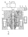
- This drum 1 has a central part 2 which is rotatably mounted on a shaft 3 which is stationary in rotation (FIG. 5).
- This tree 3 is hollow; it is dug with longitudinal holes with stepped diameters which contain three tubes 4,5,6 concentric with each other and concentric with the axis of the shaft 3, thus making appear a first cylindrical inner pipe 7, a second annular intermediate pipe 8 and a third annular external pipe 9, also concentric.
- the first cylindrical interior pipe 7 is extended by a channel 7A up to a central connection piece 10 from which flexible hoses 10A leave which lead to the peaks of the rusty disc.
- the second intermediate pipe 8 of the third external pipe 9 ends in end portions situated in transverse planes IV-IV and III-III respectively, spaced in axial direction from the shaft 3, in which radial channels 11 are formed, 12 respectively.
- the radial channels 12 end, in the thickness of the shaft 3, in an annular sectoral chamber 13, contained in this plane III-III, hollowed out on the surface of the shaft 3, and developing over 180 °.
- radial channels 14 are provided in the central part 2 of the drum 1; their number corresponds to that of the peaks of the lateral face of the drum 1 and they are regularly spaced in the circumferential direction. They are each extended in the drum 1 by longitudinal channels 15 and then by terminal radial channels 16 (FIG. 5) which lead to connection end pieces 17 from which flexible hoses 18. These last each extend respectively to peaks of the lateral surface of the drum.
- the two annular sectoral chambers 13 and 19 are arranged, in circumferential direction, in correspondence with the active sectors G and D of the drum 1 (FIG. 1) and they overlap in accordance with the common part C.
- the peaks which are joined to the radial channels 14 and 20 are supplied with water only when these channels pass, in rotation, opposite the sectoral chambers 13 and 19.
- the latter are supplied with water by the third annular external pipe 9 or by the second annular intermediate pipe 8 according to the high or low position of the drum 1.
- Das non-return valves 22, 23 are provided on the longitudinal channels 15, 21 (FIG. 5) to prevent the water sent by one circuit from flowing back through the other circuit
- the concentric pipes 7, 8, 9 are supplied with water, continuously for the pipe 7, alternately for the pipes 8, 9 at the end of the shaft 3 remote from the rusting disc of the drum, preferably from the as will now be described with reference to FIGS. 6 and 7.
- each pipe opens into a volume supply 24, 25, 26 respectively located in its extension.
- These volumes 24, 25, 26 and the end parts of the tubes 4,5, 6 are located in a fixed part 27 ending in a disc 28 arranged in a plane transverse to the axis of the cutting drum.
- This disc 28 has the thickness Just sufficient to allow the digging of radial supply channels 29,30,31,32. The latter are therefore spaced in circumferential direction; at their outer ends, they are connected to water inlet tubes 33, 34, 35, 36 respectively.
- the radial supply channel 29 opens directly into the supply volume 26 of the first cylindrical inner pipe 7.
- the radial supply channel 30 is connected by internal passages (a longitudinal passage 37 then a radial passage 38 hollowed out in the fixed part 27) to the supply volume 25 of the second intermediate annular pipe 8.
- the two supply channels 31, 32 both terminate in the supply volume 24 of the third external annular pipe 9 via internal passages longitudinal 39 and radial 40.
- the extent in the circumferential direction of the sectorial chambers 13: 1 9 is selected in correspondence with the active inventory cylindrical sectors G, D A cutting drum.
- the extent of the active sector G in the high position of the drum is generally 180 °, although it may be desired to sprinkle over a greater extent capable of reaching approximately 210 °.
- the angular extent of the active sector D in the lower position of the drum is variable depending on the height of the cutting face; it can be in practice between 60 and 180 °.
Landscapes
- Engineering & Computer Science (AREA)
- Mining & Mineral Resources (AREA)
- Mechanical Engineering (AREA)
- Life Sciences & Earth Sciences (AREA)
- General Life Sciences & Earth Sciences (AREA)
- Geochemistry & Mineralogy (AREA)
- Geology (AREA)
- Discharge Of Articles From Conveyors (AREA)
- Drilling And Exploitation, And Mining Machines And Methods (AREA)
- Nozzles (AREA)
- Perforating, Stamping-Out Or Severing By Means Other Than Cutting (AREA)
- Processing Of Stones Or Stones Resemblance Materials (AREA)
- Confectionery (AREA)
- Control Of Steam Boilers And Waste-Gas Boilers (AREA)
- Auxiliary Methods And Devices For Loading And Unloading (AREA)
- Solid Fuels And Fuel-Associated Substances (AREA)
- Shearing Machines (AREA)
- Details Or Accessories Of Spraying Plant Or Apparatus (AREA)
- Intermediate Stations On Conveyors (AREA)
- Apparatuses For Bulk Treatment Of Fruits And Vegetables And Apparatuses For Preparing Feeds (AREA)
Priority Applications (1)
| Application Number | Priority Date | Filing Date | Title |
|---|---|---|---|
| AT85402237T ATE37070T1 (de) | 1984-11-20 | 1985-11-19 | Sektorenbeduesungseinrichtung bei der kohlengewinnung. |
Applications Claiming Priority (2)
| Application Number | Priority Date | Filing Date | Title |
|---|---|---|---|
| FR8417654A FR2573474B1 (fr) | 1984-11-20 | 1984-11-20 | Dispositif d'arrosage sectoriel pour l'abattage du charbon |
| FR8417654 | 1984-11-20 |
Publications (2)
| Publication Number | Publication Date |
|---|---|
| EP0185571A1 true EP0185571A1 (de) | 1986-06-25 |
| EP0185571B1 EP0185571B1 (de) | 1988-09-07 |
Family
ID=9309752
Family Applications (1)
| Application Number | Title | Priority Date | Filing Date |
|---|---|---|---|
| EP85402237A Expired EP0185571B1 (de) | 1984-11-20 | 1985-11-19 | Sektorenbedüsungseinrichtung bei der Kohlengewinnung |
Country Status (12)
| Country | Link |
|---|---|
| US (1) | US4660892A (de) |
| EP (1) | EP0185571B1 (de) |
| JP (1) | JPS61165489A (de) |
| CN (1) | CN1004365B (de) |
| AT (1) | ATE37070T1 (de) |
| AU (1) | AU581945B2 (de) |
| DE (1) | DE3564846D1 (de) |
| ES (1) | ES8609580A1 (de) |
| FR (1) | FR2573474B1 (de) |
| IN (1) | IN165786B (de) |
| PL (1) | PL149309B1 (de) |
| ZA (1) | ZA858856B (de) |
Families Citing this family (6)
| Publication number | Priority date | Publication date | Assignee | Title |
|---|---|---|---|---|
| GB8612968D0 (en) * | 1986-05-28 | 1986-07-02 | Presswell Eng Ltd | Operating head |
| US5507565A (en) * | 1994-12-19 | 1996-04-16 | Eimco Coal Machinery, Inc. | Method and apparatus for suppressing dust and frictional ignition on a continuous mining machine |
| US6070944A (en) * | 1997-08-11 | 2000-06-06 | Eimco Llc | Phasing valve assembly for supplying water to a mining machine cutter drum |
| GB2333548B (en) * | 1997-08-11 | 2001-12-12 | Eimco Coal Machinery Inc | A method and apparatus for supplying water to a mining machine cutter drum |
| GB0200880D0 (en) * | 2002-01-16 | 2002-03-06 | Hydra Mining Tools Internat Lt | Rotary cutting head for a mining etc machine |
| CN106837327A (zh) * | 2017-04-07 | 2017-06-13 | 中国矿业大学 | 一种节水增效自控水力截割头 |
Citations (5)
| Publication number | Priority date | Publication date | Assignee | Title |
|---|---|---|---|---|
| FR1455734A (fr) * | 1964-12-05 | 1966-10-14 | Eickhoff Geb | Dispositif pour l'adduction d'un liquide à des buses d'arrosage réparties sur le pourtour d'un outil d'abatage en rotation, en particulier d'un tambour de havage |
| US3374033A (en) * | 1966-02-21 | 1968-03-19 | Lee Norse Co | Cutter head having fluid supply means |
| GB1110763A (en) * | 1963-10-29 | 1968-04-24 | Coal Industry Patents Ltd | Dust suppression means for use with mining machines |
| FR2370850A1 (fr) * | 1976-11-16 | 1978-06-09 | Coal Industry Patents Ltd | Machine d'abattage comportant un plateau de havage rotatif |
| GB2089869A (en) * | 1980-12-24 | 1982-06-30 | Paurat F | A mining machine for cutting coal and/or rock |
Family Cites Families (7)
| Publication number | Priority date | Publication date | Assignee | Title |
|---|---|---|---|---|
| GB1378456A (en) * | 1972-05-19 | 1974-12-27 | Coal Industry Patents Ltd | Apparatus for ventilating cutter-heads of mineral mining machines |
| DE2808915C2 (de) * | 1978-03-02 | 1982-07-29 | Gebr. Eickhoff, Maschinenfabrik U. Eisengiesserei Mbh, 4630 Bochum | Walzenschrämmaschine für den Untertagebergbau |
| DE3139012C2 (de) * | 1981-10-01 | 1985-02-21 | Gebr. Eickhoff Maschinenfabrik U. Eisengiesserei Mbh, 4630 Bochum | Walzenschrämmaschine für den Untertagebergbau |
| US4516807A (en) * | 1981-10-13 | 1985-05-14 | Coal Industry (Patents) Limited | Fluid supply systems for rotary cutter heads for mining machines and rotary cutter heads comprising fluid supply systems |
| AT378037B (de) * | 1982-09-09 | 1985-06-10 | Voest Alpine Ag | Vorrichtung fuer die zufuehrung einer unter druck stehenden fluessigkeit zu einem rotierenden maschinenteil |
| DE3246991A1 (de) * | 1982-12-18 | 1984-06-20 | Gebr. Eickhoff Maschinenfabrik U. Eisengiesserei Mbh, 4630 Bochum | Vorrichtung zum steuern von hochdruckfluessigkeit |
| AT378036B (de) * | 1983-04-11 | 1985-06-10 | Voest Alpine Ag | Verfahren zum bespruehen der meissel und/oder der ortsbrust mit druckfluessigkeit sowie vorrichtung zur durchfuehrung dieses verfahrens |
-
1984
- 1984-11-20 FR FR8417654A patent/FR2573474B1/fr not_active Expired
-
1985
- 1985-11-15 AU AU50026/85A patent/AU581945B2/en not_active Ceased
- 1985-11-15 PL PL1985256284A patent/PL149309B1/pl unknown
- 1985-11-16 CN CN85108377.3A patent/CN1004365B/zh not_active Expired
- 1985-11-18 ES ES549006A patent/ES8609580A1/es not_active Expired
- 1985-11-19 EP EP85402237A patent/EP0185571B1/de not_active Expired
- 1985-11-19 IN IN930/MAS/85A patent/IN165786B/en unknown
- 1985-11-19 JP JP60257896A patent/JPS61165489A/ja active Granted
- 1985-11-19 DE DE8585402237T patent/DE3564846D1/de not_active Expired
- 1985-11-19 ZA ZA858856A patent/ZA858856B/xx unknown
- 1985-11-19 AT AT85402237T patent/ATE37070T1/de not_active IP Right Cessation
- 1985-11-20 US US06/799,862 patent/US4660892A/en not_active Expired - Fee Related
Patent Citations (5)
| Publication number | Priority date | Publication date | Assignee | Title |
|---|---|---|---|---|
| GB1110763A (en) * | 1963-10-29 | 1968-04-24 | Coal Industry Patents Ltd | Dust suppression means for use with mining machines |
| FR1455734A (fr) * | 1964-12-05 | 1966-10-14 | Eickhoff Geb | Dispositif pour l'adduction d'un liquide à des buses d'arrosage réparties sur le pourtour d'un outil d'abatage en rotation, en particulier d'un tambour de havage |
| US3374033A (en) * | 1966-02-21 | 1968-03-19 | Lee Norse Co | Cutter head having fluid supply means |
| FR2370850A1 (fr) * | 1976-11-16 | 1978-06-09 | Coal Industry Patents Ltd | Machine d'abattage comportant un plateau de havage rotatif |
| GB2089869A (en) * | 1980-12-24 | 1982-06-30 | Paurat F | A mining machine for cutting coal and/or rock |
Also Published As
| Publication number | Publication date |
|---|---|
| EP0185571B1 (de) | 1988-09-07 |
| PL149309B1 (en) | 1990-01-31 |
| US4660892A (en) | 1987-04-28 |
| CN85108377A (zh) | 1986-10-01 |
| ES8609580A1 (es) | 1986-07-16 |
| ZA858856B (en) | 1986-08-27 |
| ES549006A0 (es) | 1986-07-16 |
| IN165786B (de) | 1990-01-13 |
| AU581945B2 (en) | 1989-03-09 |
| CN1004365B (zh) | 1989-05-31 |
| FR2573474A1 (fr) | 1986-05-23 |
| FR2573474B1 (fr) | 1986-12-26 |
| AU5002685A (en) | 1986-05-29 |
| DE3564846D1 (en) | 1988-10-13 |
| PL256284A1 (en) | 1986-09-23 |
| JPS61165489A (ja) | 1986-07-26 |
| JPH0327720B2 (de) | 1991-04-16 |
| ATE37070T1 (de) | 1988-09-15 |
Similar Documents
| Publication | Publication Date | Title |
|---|---|---|
| CA1091220A (fr) | Outil de forage a jet d'aspiration | |
| BE1011390A3 (fr) | Outil de forage a lames avec taillants de reserve et canaux d'evacuation des deblais generes par les taillants. | |
| FR2582473A1 (fr) | Systeme, appareillage et procede pour l'arrosage de champs de geometrie differente | |
| FR2526681A1 (fr) | Appareil rotatif d'arrosage d'eau | |
| EP0185571B1 (de) | Sektorenbedüsungseinrichtung bei der Kohlengewinnung | |
| FR2556810A1 (fr) | Distributeur de commande a inversion du sens de circulation de fluide hydraulique ou pneumatique | |
| EP0161169B2 (de) | Stumpfrodegerät | |
| FR2525066A1 (fr) | Rouleau de travail du sol | |
| FR2798405A1 (fr) | Groupe de fraisage pour le damage de pistes enneigees | |
| US3130794A (en) | Earth shaping implement | |
| FR2681264A1 (fr) | Poussoir a jet avec tete centrifuge pour le nettoyage des conduites. | |
| EP0296208B1 (de) | Bohrmeissel mit gerichtetem spülflüssigkeitsstrahl | |
| FR2513309A1 (fr) | Machine a bouclier pour forer des tunnels | |
| FR2724411A1 (fr) | Excavateur de tunnel principal-ancillaire et son procede de percage de tunnel | |
| FR2521389A1 (fr) | Dispositif de coupe pour faucheuse | |
| FR2720219A1 (fr) | Dispositif de coupe annexe pour moisonneuse-batteuse. | |
| FR2514603A1 (fr) | Versoir de charrue perfectionne | |
| FR2552841A1 (fr) | Joint tournant a distribution sectorielle | |
| EP0063089A1 (de) | Tropfenbewässerungsvorrichtungen | |
| FR2461806A1 (fr) | Machine de creusement comportant un bras muni d'un outil d'abattage et orientable | |
| EP0211128B1 (de) | Werkzeugsupport einer automatischen Drehmaschine mit Kühleinrichtung für diese Werkzeuge | |
| FR2732380A1 (fr) | Procede et dispositif pour maintenir en service un drainage d'evacuation pendant une construction de canalisation | |
| FR2548864A1 (fr) | Dispositif de coupe pour tondeuse ou faucheuse | |
| WO1999001340A1 (fr) | Dispositif de stabilisation pour bateau a voile | |
| EP0511276B1 (de) | Wendekörper |
Legal Events
| Date | Code | Title | Description |
|---|---|---|---|
| PUAI | Public reference made under article 153(3) epc to a published international application that has entered the european phase |
Free format text: ORIGINAL CODE: 0009012 |
|
| AK | Designated contracting states |
Kind code of ref document: A1 Designated state(s): AT BE DE GB SE |
|
| 17P | Request for examination filed |
Effective date: 19861127 |
|
| RAP1 | Party data changed (applicant data changed or rights of an application transferred) |
Owner name: CHARBONNAGES DE FRANCE, ETABLISSEMENT PUBLIC DITE: |
|
| RAP1 | Party data changed (applicant data changed or rights of an application transferred) |
Owner name: CHARBONNAGES DE FRANCE, ETABLISSEMENT PUBLIC DIT: |
|
| 17Q | First examination report despatched |
Effective date: 19870722 |
|
| GRAA | (expected) grant |
Free format text: ORIGINAL CODE: 0009210 |
|
| AK | Designated contracting states |
Kind code of ref document: B1 Designated state(s): AT BE DE GB SE |
|
| REF | Corresponds to: |
Ref document number: 37070 Country of ref document: AT Date of ref document: 19880915 Kind code of ref document: T |
|
| GBT | Gb: translation of ep patent filed (gb section 77(6)(a)/1977) | ||
| REF | Corresponds to: |
Ref document number: 3564846 Country of ref document: DE Date of ref document: 19881013 |
|
| PLBE | No opposition filed within time limit |
Free format text: ORIGINAL CODE: 0009261 |
|
| STAA | Information on the status of an ep patent application or granted ep patent |
Free format text: STATUS: NO OPPOSITION FILED WITHIN TIME LIMIT |
|
| 26N | No opposition filed | ||
| PGFP | Annual fee paid to national office [announced via postgrant information from national office to epo] |
Ref country code: SE Payment date: 19891019 Year of fee payment: 5 |
|
| PGFP | Annual fee paid to national office [announced via postgrant information from national office to epo] |
Ref country code: BE Payment date: 19891128 Year of fee payment: 5 |
|
| PGFP | Annual fee paid to national office [announced via postgrant information from national office to epo] |
Ref country code: GB Payment date: 19901005 Year of fee payment: 6 |
|
| PG25 | Lapsed in a contracting state [announced via postgrant information from national office to epo] |
Ref country code: SE Effective date: 19901120 |
|
| PGFP | Annual fee paid to national office [announced via postgrant information from national office to epo] |
Ref country code: AT Payment date: 19901126 Year of fee payment: 6 |
|
| PG25 | Lapsed in a contracting state [announced via postgrant information from national office to epo] |
Ref country code: BE Effective date: 19901130 |
|
| PGFP | Annual fee paid to national office [announced via postgrant information from national office to epo] |
Ref country code: DE Payment date: 19910130 Year of fee payment: 6 |
|
| BERE | Be: lapsed |
Owner name: CHARBONNAGES DE FRANCE Effective date: 19901130 |
|
| PG25 | Lapsed in a contracting state [announced via postgrant information from national office to epo] |
Ref country code: GB Effective date: 19911119 Ref country code: AT Effective date: 19911119 |
|
| GBPC | Gb: european patent ceased through non-payment of renewal fee | ||
| PG25 | Lapsed in a contracting state [announced via postgrant information from national office to epo] |
Ref country code: DE Effective date: 19920801 |
|
| EUG | Se: european patent has lapsed |
Ref document number: 85402237.3 Effective date: 19910705 |