EP0185579B1 - Verfahren zur Verschiebung eines beweglichen Systems, das durch einen elektrischen Motor in einer gegebenen Bahn angetrieben wird - Google Patents
Verfahren zur Verschiebung eines beweglichen Systems, das durch einen elektrischen Motor in einer gegebenen Bahn angetrieben wird Download PDFInfo
- Publication number
- EP0185579B1 EP0185579B1 EP85402324A EP85402324A EP0185579B1 EP 0185579 B1 EP0185579 B1 EP 0185579B1 EP 85402324 A EP85402324 A EP 85402324A EP 85402324 A EP85402324 A EP 85402324A EP 0185579 B1 EP0185579 B1 EP 0185579B1
- Authority
- EP
- European Patent Office
- Prior art keywords
- point
- current
- mobile
- motor
- mobile system
- Prior art date
- Legal status (The legal status is an assumption and is not a legal conclusion. Google has not performed a legal analysis and makes no representation as to the accuracy of the status listed.)
- Expired
Links
Images


Classifications
-
- G—PHYSICS
- G11—INFORMATION STORAGE
- G11B—INFORMATION STORAGE BASED ON RELATIVE MOVEMENT BETWEEN RECORD CARRIER AND TRANSDUCER
- G11B5/00—Recording by magnetisation or demagnetisation of a record carrier; Reproducing by magnetic means; Record carriers therefor
- G11B5/48—Disposition or mounting of heads or head supports relative to record carriers ; arrangements of heads, e.g. for scanning the record carrier to increase the relative speed
- G11B5/54—Disposition or mounting of heads or head supports relative to record carriers ; arrangements of heads, e.g. for scanning the record carrier to increase the relative speed with provision for moving the head into or out of its operative position or across tracks
- G11B5/55—Track change, selection or acquisition by displacement of the head
- G11B5/5521—Track change, selection or acquisition by displacement of the head across disk tracks
- G11B5/5526—Control therefor; circuits, track configurations or relative disposition of servo-information transducers and servo-information tracks for control thereof
- G11B5/553—Details
- G11B5/5547—"Seek" control and circuits therefor
-
- G—PHYSICS
- G08—SIGNALLING
- G08B—SIGNALLING SYSTEMS, e.g. PERSONAL CALLING SYSTEMS; ORDER TELEGRAPHS; ALARM SYSTEMS
- G08B1/00—Systems for signalling characterised solely by the form of transmission of the signal
- G08B1/08—Systems for signalling characterised solely by the form of transmission of the signal using electric transmission ; transformation of alarm signals to electrical signals from a different medium, e.g. transmission of an electric alarm signal upon detection of an audible alarm signal
-
- G—PHYSICS
- G11—INFORMATION STORAGE
- G11B—INFORMATION STORAGE BASED ON RELATIVE MOVEMENT BETWEEN RECORD CARRIER AND TRANSDUCER
- G11B5/00—Recording by magnetisation or demagnetisation of a record carrier; Reproducing by magnetic means; Record carriers therefor
- G11B5/48—Disposition or mounting of heads or head supports relative to record carriers ; arrangements of heads, e.g. for scanning the record carrier to increase the relative speed
- G11B5/54—Disposition or mounting of heads or head supports relative to record carriers ; arrangements of heads, e.g. for scanning the record carrier to increase the relative speed with provision for moving the head into or out of its operative position or across tracks
-
- Y—GENERAL TAGGING OF NEW TECHNOLOGICAL DEVELOPMENTS; GENERAL TAGGING OF CROSS-SECTIONAL TECHNOLOGIES SPANNING OVER SEVERAL SECTIONS OF THE IPC; TECHNICAL SUBJECTS COVERED BY FORMER USPC CROSS-REFERENCE ART COLLECTIONS [XRACs] AND DIGESTS
- Y10—TECHNICAL SUBJECTS COVERED BY FORMER USPC
- Y10S—TECHNICAL SUBJECTS COVERED BY FORMER USPC CROSS-REFERENCE ART COLLECTIONS [XRACs] AND DIGESTS
- Y10S388/00—Electricity: motor control systems
- Y10S388/907—Specific control circuit element or device
- Y10S388/915—Sawtooth or ramp waveform generator
Definitions
- the invention relates to a method for moving a mobile system driven by an electric motor along a given trajectory and its implementation device. It is more particularly applicable to systems for moving and loading heads comprising the transducers for reading and writing magnetic disks of a disk memory.
- Each side of a magnetic disc is associated, most often a single write / read transducer. So that this transducer can write or read any information contained on the face which is associated with it, it is placed on a platform which is moved parallel to the face of the disc by means of a linear or rotary electrodynamic motor.
- the platform itself is made up of two essential parts, namely on the one hand, a part called the head which comprises the transducers and on the other hand a suspension device of which one end is integral with the head and the other end secured to a rigid arm secured to the movable part of the electrodynamic motor.
- the head comprising the transducer (s) for reading / writing one face of a disc has the shape of a relatively flat rectangular parallelepiped whose underside disposed facing the disc comprises the transducer.
- the large upper face parallel to the previous one contains the ends of the electrical wires entering and / or leaving the transducer and the means making it possible to connect these wires to the electronic circuits for reading and / or writing from the disk memory.
- the rotation of the disc causes the existence between the underside of the head of the platform and the face of the disc associated with the transducer thereof, a compressed air cushion which prevents the head from touching the disc and as a result of deteriorating it. It is said that the head flies above the face of the disc associated with it. Under these conditions, the distance between the face of the disc and the underside of the head is called “flight height h. It should be noted that the head is also called flight pad in current practice.
- the dynamic balance of the platform in flight is obtained by opposing the pressure force created by the air cushion on the surface of the underside of the platform a force called "charge directed in opposite direction, applied on the upper face of the head and of modulus equal to that of the pressing force.
- the load is relatively low, of the order of 10 to 15 grams. It is provided by a load blade secured to the rigid removable arm.
- a delicate problem to solve is that of the flight of the head.
- the head is in a position located in the vicinity of the periphery of the disk outside of it, called the "rest position" for which the distance H between the face bottom of the head and the plane containing the face of the disc associated with the head, is of the order of a few tenths of a millimeter.
- the rest position for which the distance H between the face bottom of the head and the plane containing the face of the disc associated with the head, is of the order of a few tenths of a millimeter.
- To allow the flight of the head it is therefore necessary to move it from its rest position outside the disc to the position where it is lowered towards the disc in stable flight position, at a height h of a few tenths of a micron above the surface of the disc.
- the flight is delicate mainly because of the air turbulence near the surface of the disc.
- putting the head in flight consists of moving it from a position where its distance from the disc is H, to a position where it is loaded so that it flies so stable above the surface of the disk, its distance from the latter being h less than H.
- the positioner is mounted on ball bearings.
- the load of each head is supplied, as mentioned above, by a load blade articulated by one of its ends to an arm secured to the rotary positioner and carrying at its other end a suspension device of the head.
- This blade is itself mechanically connected to a wire on which a pusher mounted on the end of an articulated leaf spring rests. on the arm integral with the positioner.
- the pusher is in contact with the profile of a fixed cam.
- the profile of this cam comprises two slope breaking points thus dividing it into three distinct parts.
- the head displacement and loading system can be likened to a mobile system which moves along a given trajectory formed by the three parts of the profile of the cam.
- the mobile system constituted by the displacement and head loading system to a mobile constituted by the pusher moving along the profile of the cam and having the same mass and the same inertia. than the head moving and loading system.
- the present invention relates to a first method for moving the mobile system constituted by the system for moving and loading heads along the second part of the profile of the cam between the two break-off points, so that the mobile crosses the second break point with a speed between two predetermined values, the friction forces to which the mobile is subjected being constant for the same journey, but may vary from one journey to another and from a disk memory to the other.
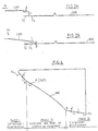
- the ACRO rotary actuator has a rotation axis ⁇ .
- the POSROT rotary positioner comprises on the one hand an ARMOB metal frame made of a light metal, and on the other hand the support arm BS (which is seen in more detail shown in perspective in FIG. 3) which carries the DISAD device.
- the DISAD device is controlled by a fixed CAM cam with which it is in contact via the pusher P.
- the cam CAM has a profile which can be seen in more detail in FIG. 4.
- This profile comprises three parts, namely two straight lines S 1 and S 2 separated by an arc of a circle AB centered on the axis of rotation ( ⁇ ) of the rotary actuator.
- the line segment S 1 is separated from the arc of circle AB by a first break point of slope A while the arc of circle AB and the second line segment S 2 are separated by a second break point of slope B.
- the pusher P which is in contact with the profile of the cam, as shown in FIG. 4, moves along the latter between the points A 'and C.
- the push-button P will move successively on the profile parts A'A, AB and BC.
- the SCT system is immobilized (locked).
- the SCT system is unlocked by sending a current to the ACRO rotary electrodynamic motor.
- the pusher P then moves on the segment Si between the points A 'and A.
- the head T is disposed outside the disc DISC, at a height H above the plane of the disc DISC.
- the pusher P has reached the first break point A begins the second phase described below.
- Phase 2 Approaching the heads in the loading position.
- the pusher P moves from the first slope break point A to the second slope break point B by borrowing the second part of the profile of the cam CAM, namely the arc of a circle AB.
- the head T is brought from the position it occupied outside the disc during the locking phase to a position located above the disc, opposite the circle Ci (see FIGS. 1 A, 1 B and 2) located at the periphery of the DISC disc.
- the head T moves parallel to the plane of the disc DISC, that is to say that it remains at a distance H from the plane of the disc.
- the position of the pusher P is such that the leaf spring LRS exerts a thrust on the wire F which in turn exerts a tensile force F T (see FIG. 2A) on the blade loading LAM which thus maintains the head T at a height H from the plane of the disc DISC.
- phase 3 is approached.
- Phase 3 Actual loading.
- the pusher moves from the second breaking point B to point C on the second line segment S 2 .
- the leaf spring LRS moves away from the edge of the support arm BS, so that the wire F releases its tensile force F T on the load blade LAM, which causes the lowering of the latter towards the disc DISC.
- This causes the loading of the head T on the disc DISC, the distance between the underside of the head T and the disc DISC then being equal to h, flight height of the order of a few tenths of a micron (FIG. 2B), the pusher P having left the surface S 2 of the cam.
- the head is then opposite the circle C 2 ( Figures 1A, 1B).
- the SCT system is a mobile system moving along a trajectory A'ABC.
- This mobile system is subjected, during the course of the trajectory A'ABC, to resistant forces which, as was said above, remain constant for the same course of the trajectory A'ABC and can vary from one course of the trajectory to another (whether for the same disk memory or for different memories).
- the SCT system by moving the SCT system by means of a control current in the rotary electrodynamic motor having a given intensity and duration, ensuring that this system has correct displacement conditions (i.e. displacement in the minimum time, loading the head T with a speed between two predetermined values given allowing it to be at the required flight altitude without touching the disc), in given environmental conditions, it may be that the same control current, in other environmental conditions, does not allow correct movement of the heads.
- the displacement time may then be too short, the heads being liable to strike the disc, or else the displacement system may fail to cross the second break point B, and then the head T cannot be loaded.
- the first object of the invention relates to a first method for moving a mobile system secured to an electric motor along a given trajectory (AB) overcoming the above drawbacks by moving the mobile according to phase 2 of the movement under the best conditions ( minimum time, assurance that the end point is reached with a speed between two predetermined values), whatever the environmental conditions.
- the second object of the invention also relates to a second method for moving a system for moving and loading heads secured to an electric motor along a given trajectory A'ABC (at two break point gradient) overcoming the drawbacks mentioned above above, by moving the system according to all of the three phases 1, 2, 3 mentioned above.
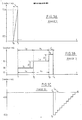
- Phase 1 (illustrated by FIG. 5A): One sends in the armature of the rotary electrodynamic motor a current in the form of a ramp, the intensity of which increases linearly as a function of time. During this phase, it is constantly checked whether the mobile system constituted by the SCT system passes to point A. A preferred mode of detection of the passage from the mobile system to point A will be described later. This detection mode is identical to the detection mode for the passage of the mobile system at point B. The current ramp begins at time T o and ends at time T 1 where the passage of the mobile system has been detected. at point A.
- the time interval T 1 - T o is for example of the order of 25 to 30 milliseconds, whereas between the instants T o and T 1 , the current intensity varies linearly from 0 to a few hundreds of milliamps (700 milliamps in Figure 5A).
- T 1 we pass to the second phase corresponding to the implementation of the method according to the invention.
- i 2 is the intensity of the pulse 1 2 and i 1 the intensity of the pulse 1 1
- V 1 and V 2 are determined experimentally.
- ⁇ i The value of ⁇ i is established experimentally and depends on the maximum speed V 2 . (If ⁇ i is too large, the speed of the mobile system may exceed V 2 at the point of slope break B).
- phase 2 where the method according to the invention is implemented, a succession of pulses of increasing intensity and of the same duration is applied to the armature of the motor, and during the application of each pulse if the mobile passes to the destination point B.
- the current is incremented by successive steps of a validation duration t v , which amounts to saying that the speed of the mobile system is incremented by successive steps of the same validation duration t v .
- the current pulses have been arbitrarily assumed to be positive.
- a current pulse is sent at time T ' 4 in the armature of the motor, in the opposite direction to the pulses I 1 , 1 2 , 1 3 , that is to say negative in the example.
- This time t 4 is of the order of a few tens of milliseconds.
- I F be this braking pulse. Its intensity has been calculated so that it allows immobilization of the mobile system, when the latter has maximum acceleration at point B due to the reaction of the cam on the pusher. This maximum acceleration is determined experimentally.
- the duration t 4 was chosen so that, the acceleration at point B being assumed to be maximum (i.e. the driving force due to the reaction of the cam on the pusher being assumed to be maximum), the intensity being chosen equal to that determined previously (for example of the order of 500 milliamps), the SCT system is immobilized without residual oscillations.
- the duration t 4 corresponds to the duration of the transient regime during which the angular speed w of the head loading system T passes from the value it had just before the application of the braking pulse, to a zero value (see Figure 6).
- the mobile system is immobilized, it is in equilibrium under the action of, on the one hand, the driving force due to the reaction of the cam on the pusher, and, on the other hand, the resistive torque exerted by the motor and the forces of friction.
- a current decreasing linearly as a function of time is applied to the armature of the motor as indicated for example in FIGS. 5C and 6, the duration of this decreasing current ramp being of the order of 200 at 300 milliseconds.
- This ramp can be obtained, for example, in the form of a succession of ten steps, the duration of each step being of the order of 20 milliseconds.
- the shape of the angular speed is then that indicated in FIG. 6. After a certain time the speed stabilizes and remains substantially constant until the mobile reaches point C. After the last level where the current is zero in the armature of the motor, a short duration positive current pulse is sent so that the displacement and head loading system reaches a predetermined position, the limit point of its trajectory beyond which it cannot move (by construction).
- the variation in acceleration of the mobile system is measured. This is obtained by measuring and then differentiating the counterelectromotive force of the linear electrodynamic motor.
- the threshold value is determined experimentally, so that it is significantly greater than the average acceleration calculated both on the path A'A (to detect the passage at point A) and on the path AB (to detect the go to point B).
- the values of the thresholds for detecting the passage of the mobile system at points A and B are generally different.
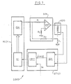
- FIG. 7 An example of a device for implementing the second method for moving the SCT movement and loading system according to phases 1, 2 and 3 according to the invention is shown in FIG. 7.
- the resistor R 3 connects the positive input of the amplifier to ground, while the resistor R I connects the output of the control means MCOM to the negative input of the amplifier AMP, the resistor R 2 connects the input of the generator GEN to one of the terminals of the armature of the ACRO motor, this same terminal being connected via a resistor R 4 to ground.
- the output of AMP is located at the other terminal of the armature of ACRO.
- This generator GEN transforms the voltage pulses it receives from the control means MCOM into current pulses such as those shown in FIGS. 5A, 5B and 5C.
- the control means MCOM include, an instruction generator GI delivering instructions in binary form to a digital analog converter CDA.
- the instruction generator Gl in a preferred embodiment of the invention is a microprocessor containing a microprogram delivering a sequence of binary instructions to the digital analog converter CDA, according to an algorithm which is represented in figure 8.
- To each binary value sent by the instruction generator GI to the digital analog converter CDA corresponds, to the output of the latter, a voltage pulse, transformed into a current pulse by the generator GEN.
- the DIF differentiation means differentiate the electromotive force e taken across the armature of the ACRO motor.
- This comparator sends a linear value 0 to the instruction generator GI, as long as the acceleration remains below the threshold SA, and sends a binary value equal to 1 when the acceleration has exceeded this threshold SA, that is to say when the mobile system has passed either to point A or to point B.
Landscapes
- Physics & Mathematics (AREA)
- General Physics & Mathematics (AREA)
- Supporting Of Heads In Record-Carrier Devices (AREA)
- Control Of Position Or Direction (AREA)
- Control Of Electric Motors In General (AREA)
- Moving Of Heads (AREA)
- Control Of Linear Motors (AREA)
Claims (5)
Applications Claiming Priority (2)
| Application Number | Priority Date | Filing Date | Title |
|---|---|---|---|
| FR8418157A FR2573904B1 (fr) | 1984-11-29 | 1984-11-29 | Procede pour deplacer un systeme mobile mu par un moteur electrique suivant une trajectoire donnee |
| FR8418157 | 1984-11-29 |
Publications (2)
| Publication Number | Publication Date |
|---|---|
| EP0185579A1 EP0185579A1 (de) | 1986-06-25 |
| EP0185579B1 true EP0185579B1 (de) | 1989-11-02 |
Family
ID=9310040
Family Applications (1)
| Application Number | Title | Priority Date | Filing Date |
|---|---|---|---|
| EP85402324A Expired EP0185579B1 (de) | 1984-11-29 | 1985-11-27 | Verfahren zur Verschiebung eines beweglichen Systems, das durch einen elektrischen Motor in einer gegebenen Bahn angetrieben wird |
Country Status (5)
| Country | Link |
|---|---|
| US (1) | US4755892A (de) |
| EP (1) | EP0185579B1 (de) |
| JP (1) | JPS61139293A (de) |
| DE (1) | DE3574066D1 (de) |
| FR (1) | FR2573904B1 (de) |
Families Citing this family (27)
| Publication number | Priority date | Publication date | Assignee | Title |
|---|---|---|---|---|
| US4864437A (en) * | 1988-03-07 | 1989-09-05 | Syquest Technology | Head loading velocity control |
| US5027239A (en) * | 1989-12-22 | 1991-06-25 | Seagate Technology, Inc. | Routing a sleeve and conductors in a head-gimbal assembly |
| JPH04289568A (ja) * | 1991-02-27 | 1992-10-14 | Matsushita Electric Ind Co Ltd | 磁気ヘッドのローディング方法 |
| US5471353A (en) * | 1992-12-18 | 1995-11-28 | Western Digital (Sea), Pte., Ltd. | Disk drive employing multi-mode spindle drive system |
| US5485323A (en) * | 1993-07-14 | 1996-01-16 | International Business Machines Corporation | Method and apparatus for moving a disk drive actuator away from a magnetic latch |
| US5625514A (en) * | 1993-12-14 | 1997-04-29 | Sony Corporation | Disk Device |
| US5455723A (en) * | 1994-06-02 | 1995-10-03 | International Business Machines Corporation | Method and apparatus for ramp load and unload |
| US5828522A (en) * | 1994-09-13 | 1998-10-27 | International Business Machines Corporation | Velocity control of head load/unload mechanism in a disk drive using dither |
| US5615064A (en) * | 1994-10-03 | 1997-03-25 | International Business Machines Corporation | Pulsed current velocity controlled head load method and apparatus which uses the back EMF to control the generation of head actuator driving pulses |
| US5769912A (en) * | 1995-10-16 | 1998-06-23 | Mansur Industries Inc. | System and method of vapor recovery in industrial washing equipment |
| US5768045A (en) * | 1995-12-20 | 1998-06-16 | Western Digital Corporation | Hardware velocity limit control system |
| US5930078A (en) * | 1996-05-07 | 1999-07-27 | International Business Machines Corporation | Automated head wire stringing, termination, and slider bonding suspension assembly with load/unload feature |
| US5781363A (en) * | 1996-10-15 | 1998-07-14 | International Business Machines Corporation | Servo-free velocity estimator for coil driven actuator arm in a data storage drive |
| US6154340A (en) * | 1996-11-22 | 2000-11-28 | Seagate Technology, Inc. | Low velocity disk drive load controller |
| US5966732A (en) * | 1996-12-02 | 1999-10-12 | Gateway 2000, Inc. | Method and apparatus for adding to the reserve area of a disk drive |
| KR100255207B1 (ko) * | 1997-01-28 | 2000-05-01 | 윤종용 | 하드 디스크 드라이브의 안정된 언래치 제어 방법 |
| US6320717B1 (en) * | 1998-10-30 | 2001-11-20 | Iomega Corporation | Velocity limited loading of read heads onto disk drive media |
| US6317284B1 (en) | 1998-10-30 | 2001-11-13 | Iomega Corporation | Head nudge and park peak current suppression |
| US6754027B2 (en) | 2000-04-26 | 2004-06-22 | Fujitsu Limited | Head speed control method, head position detection method and disk unit |
| JP2002319257A (ja) * | 2001-04-23 | 2002-10-31 | Fujitsu Ltd | ロード/アンロード動作制御方法及び記憶装置 |
| US7082009B2 (en) | 2003-02-19 | 2006-07-25 | Matsushita Electric Industrial Co., Ltd. | Accurate tracking of coil resistance based on current, voltage and angular velocity |
| US7009806B2 (en) * | 2003-02-19 | 2006-03-07 | Matsushita Electric Industrial Co., Ltd. | Accurate tracking of coil resistance |
| US6917486B2 (en) * | 2003-07-18 | 2005-07-12 | Matsushita Electrical Industrial Co., Ltd. | Direct detection of coil resistance |
| US8009388B2 (en) * | 2006-10-10 | 2011-08-30 | Seagate Technology Llc | Method for increasing storage capacity and a transducer configuration incorporating the same |
| JP2009026459A (ja) * | 2008-11-04 | 2009-02-05 | Fujitsu Ltd | ロード/アンロード動作制御方法及び記憶装置 |
| US9230593B1 (en) * | 2014-12-23 | 2016-01-05 | Western Digital Technologies, Inc. | Data storage device optimizing spindle motor power when transitioning into a power failure mode |
| US9355676B1 (en) | 2015-03-25 | 2016-05-31 | Western Digital Technologies, Inc. | Data storage device controlling amplitude and phase of driving voltage to generate power from a spindle motor |
Family Cites Families (11)
| Publication number | Priority date | Publication date | Assignee | Title |
|---|---|---|---|---|
| CH402120A (de) * | 1959-12-24 | 1965-11-15 | Licentia Gmbh | Verfahren und Durchführungsanordnung zur numerischen Werkzeugmaschinensteuerung |
| FR1491735A (fr) * | 1965-09-03 | 1967-08-11 | Olivetti & Co Spa | Dispositif de commande de positionnement comprenant un organe d'interpolation |
| US3932796A (en) * | 1972-02-09 | 1976-01-13 | Textron, Inc. | Control system for producing multi-axis contour movement for a stepping motor drive |
| BE795583A (fr) * | 1972-02-18 | 1973-08-16 | Philips Nv | Procede et dispositif de positionnement |
| US4202020A (en) * | 1978-08-31 | 1980-05-06 | International Business Machines Corporation | Magnetic head load control system |
| US4660106A (en) * | 1980-09-24 | 1987-04-21 | Quantum Corporation | Data transducer position control system for rotating disk data storage equipment |
| BR8203829A (pt) * | 1981-07-02 | 1983-06-28 | Irwin Int Inc | Aparelho posicionador para conduzir uma cabeca captadora braco pivot e sistema de controle aperfeicoado para sistema impulsor do tipo de disco |
| FR2523346B1 (fr) * | 1982-03-15 | 1988-06-10 | Cii Honeywell Bull | Dispositif de chargement de corps principal de plate-forme comportant au moins un transducteur de lecture/ecriture d'un support d'informations |
| JPS58177571A (ja) * | 1982-04-09 | 1983-10-18 | Hitachi Ltd | 磁気デイスク装置 |
| JPS59198572A (ja) * | 1983-04-26 | 1984-11-10 | Fujitsu Ltd | 磁気ヘツド位置決め制御方式 |
| ZA847740B (en) * | 1983-10-12 | 1985-05-29 | Byrne & Davidson Ind Ltd | Obstruction detection means |
-
1984
- 1984-11-29 FR FR8418157A patent/FR2573904B1/fr not_active Expired
-
1985
- 1985-11-27 DE DE8585402324T patent/DE3574066D1/de not_active Expired
- 1985-11-27 EP EP85402324A patent/EP0185579B1/de not_active Expired
- 1985-11-29 JP JP60267611A patent/JPS61139293A/ja active Pending
- 1985-11-29 US US06/803,509 patent/US4755892A/en not_active Expired - Fee Related
Also Published As
| Publication number | Publication date |
|---|---|
| US4755892A (en) | 1988-07-05 |
| FR2573904A1 (fr) | 1986-05-30 |
| EP0185579A1 (de) | 1986-06-25 |
| FR2573904B1 (fr) | 1987-01-02 |
| DE3574066D1 (en) | 1989-12-07 |
| JPS61139293A (ja) | 1986-06-26 |
Similar Documents
| Publication | Publication Date | Title |
|---|---|---|
| EP0185579B1 (de) | Verfahren zur Verschiebung eines beweglichen Systems, das durch einen elektrischen Motor in einer gegebenen Bahn angetrieben wird | |
| EP0184500B1 (de) | Verfahren zur Verschiebung eines beweglichen Systems, das durch einen elektrischen Motor in einer gegebenen Bahn angetrieben wird und Anordnung zur Realisierung dieses Verfahrens | |
| EP2113476B1 (de) | Sicherheitsvorrichtung für Verladerampen oder Entladerampen | |
| EP1020019B1 (de) | Gerät und verfahren zur steuerung eines synchronmotors mit permanentmagnet | |
| JP2006202379A (ja) | ディスク処理装置 | |
| FR2536886A1 (fr) | Dispositif d'enregistrement de donnees concernant le fonctionnement d'une machine | |
| FR2514162A1 (fr) | Servomecanisme et procede pour commander automatiquement la vitesse de vehicules | |
| FR2523104A1 (fr) | Systeme d'ascenceur a comparaison des signaux de vitesse | |
| EP2236449A1 (de) | Hubvorrichtung mit einem Greiffer und eine Steuerungsvorrichtung zum activieren und deaktivieren des Greiffers. | |
| WO1988006928A1 (fr) | Ensemble de calibrage de produits, tels que des fruits | |
| EP0921070B1 (de) | Stellantrieb für die Steuerfläche eines Flugzeuges | |
| EP0022270A1 (de) | Stellungsdetektor für einen Schrittmotor | |
| FR2489030A1 (fr) | Appareil d'enregistrement et de lecture de bandes sous cassette comportant un systeme d'entrainement rapide vers l'avant | |
| FR2486731A1 (fr) | Dispositif de regulation de la vitesse de rotation d'un moteur electrique | |
| CA1243378A (fr) | Procede de commande du freinage d'un vehicule sur roues | |
| EP2236450A1 (de) | Hubvorrichtung mit einem Bewegungssensor | |
| EP0102897A1 (de) | Automatische Reinigungsvorrichtung eines Lesekopfes eines Kassettenaufnahmegerätes | |
| EP0478430A1 (de) | Friktionstellantrieb | |
| FR2470506A1 (fr) | Dispositif de freinage d'un moteur de rotation, et lecteur de videodisque comprenant un tel dispositif | |
| JP2000510635A (ja) | 低速度のもとでヘッドをローディングして行うヘッドクリーニング | |
| FR2633740A1 (fr) | Procede et dispositif de reperage d'un vehicule automatique | |
| FR2964357A1 (fr) | Controle actif d'un ecoulement d'air sur un aileron par un actionneur electroarodynamique | |
| FR2881821A1 (fr) | Missile teleguide | |
| FR2588375A1 (fr) | Dispositif de detection de la position d'un corps par rapport a un point | |
| EP0306355B1 (de) | Verbundene automatische Regelung der Trimmung und Leistung für die allgemeine Handels- und Geschäftsluftfahrt |
Legal Events
| Date | Code | Title | Description |
|---|---|---|---|
| PUAI | Public reference made under article 153(3) epc to a published international application that has entered the european phase |
Free format text: ORIGINAL CODE: 0009012 |
|
| AK | Designated contracting states |
Kind code of ref document: A1 Designated state(s): DE FR GB IT NL SE |
|
| 17P | Request for examination filed |
Effective date: 19860628 |
|
| 17Q | First examination report despatched |
Effective date: 19880225 |
|
| RAP1 | Party data changed (applicant data changed or rights of an application transferred) |
Owner name: BULL S.A. |
|
| GRAA | (expected) grant |
Free format text: ORIGINAL CODE: 0009210 |
|
| PGFP | Annual fee paid to national office [announced via postgrant information from national office to epo] |
Ref country code: FR Payment date: 19890928 Year of fee payment: 5 |
|
| AK | Designated contracting states |
Kind code of ref document: B1 Designated state(s): DE FR GB IT NL SE |
|
| ITF | It: translation for a ep patent filed | ||
| PGFP | Annual fee paid to national office [announced via postgrant information from national office to epo] |
Ref country code: SE Payment date: 19891130 Year of fee payment: 5 Ref country code: NL Payment date: 19891130 Year of fee payment: 5 Ref country code: GB Payment date: 19891130 Year of fee payment: 5 |
|
| PGFP | Annual fee paid to national office [announced via postgrant information from national office to epo] |
Ref country code: DE Payment date: 19891207 Year of fee payment: 5 |
|
| REF | Corresponds to: |
Ref document number: 3574066 Country of ref document: DE Date of ref document: 19891207 |
|
| GBT | Gb: translation of ep patent filed (gb section 77(6)(a)/1977) | ||
| PLBE | No opposition filed within time limit |
Free format text: ORIGINAL CODE: 0009261 |
|
| STAA | Information on the status of an ep patent application or granted ep patent |
Free format text: STATUS: NO OPPOSITION FILED WITHIN TIME LIMIT |
|
| 26N | No opposition filed | ||
| PG25 | Lapsed in a contracting state [announced via postgrant information from national office to epo] |
Ref country code: GB Effective date: 19901127 |
|
| PG25 | Lapsed in a contracting state [announced via postgrant information from national office to epo] |
Ref country code: SE Effective date: 19901128 |
|
| PG25 | Lapsed in a contracting state [announced via postgrant information from national office to epo] |
Ref country code: NL Effective date: 19910601 |
|
| NLV4 | Nl: lapsed or anulled due to non-payment of the annual fee | ||
| GBPC | Gb: european patent ceased through non-payment of renewal fee | ||
| PG25 | Lapsed in a contracting state [announced via postgrant information from national office to epo] |
Ref country code: FR Effective date: 19910731 |
|
| PG25 | Lapsed in a contracting state [announced via postgrant information from national office to epo] |
Ref country code: DE Effective date: 19910801 |
|
| REG | Reference to a national code |
Ref country code: FR Ref legal event code: ST |
|
| EUG | Se: european patent has lapsed |
Ref document number: 85402324.9 Effective date: 19910705 |