EP0185594B1 - Reibungs- und Wirbelstromverbundkupplung und Verfahren zu ihrer Steuerung - Google Patents
Reibungs- und Wirbelstromverbundkupplung und Verfahren zu ihrer Steuerung Download PDFInfo
- Publication number
- EP0185594B1 EP0185594B1 EP19850402548 EP85402548A EP0185594B1 EP 0185594 B1 EP0185594 B1 EP 0185594B1 EP 19850402548 EP19850402548 EP 19850402548 EP 85402548 A EP85402548 A EP 85402548A EP 0185594 B1 EP0185594 B1 EP 0185594B1
- Authority
- EP
- European Patent Office
- Prior art keywords
- clutch
- rotor
- respect
- excitation
- coupling arrangement
- Prior art date
- Legal status (The legal status is an assumption and is not a legal conclusion. Google has not performed a legal analysis and makes no representation as to the accuracy of the status listed.)
- Expired - Lifetime
Links
- 238000000034 method Methods 0.000 title claims description 12
- 150000001875 compounds Chemical class 0.000 title 1
- 230000005284 excitation Effects 0.000 claims description 73
- 230000006698 induction Effects 0.000 claims description 29
- 230000005540 biological transmission Effects 0.000 claims description 26
- 230000008878 coupling Effects 0.000 claims description 19
- 238000010168 coupling process Methods 0.000 claims description 19
- 238000005859 coupling reaction Methods 0.000 claims description 19
- 241000282472 Canis lupus familiaris Species 0.000 claims description 17
- 238000013016 damping Methods 0.000 claims description 9
- 230000004907 flux Effects 0.000 claims description 9
- 238000006073 displacement reaction Methods 0.000 claims description 3
- 238000005520 cutting process Methods 0.000 claims description 2
- 238000005096 rolling process Methods 0.000 claims 2
- 238000013519 translation Methods 0.000 description 10
- 230000006870 function Effects 0.000 description 8
- 229910001209 Low-carbon steel Inorganic materials 0.000 description 7
- 230000010355 oscillation Effects 0.000 description 7
- 230000008859 change Effects 0.000 description 6
- 238000006243 chemical reaction Methods 0.000 description 4
- 230000007423 decrease Effects 0.000 description 4
- 230000008901 benefit Effects 0.000 description 3
- 230000000694 effects Effects 0.000 description 3
- 230000009471 action Effects 0.000 description 2
- 230000003042 antagnostic effect Effects 0.000 description 2
- 238000010586 diagram Methods 0.000 description 2
- 230000005520 electrodynamics Effects 0.000 description 2
- 238000005516 engineering process Methods 0.000 description 2
- 235000021183 entrée Nutrition 0.000 description 2
- 230000007246 mechanism Effects 0.000 description 2
- 239000002184 metal Substances 0.000 description 2
- 230000009467 reduction Effects 0.000 description 2
- 230000004044 response Effects 0.000 description 2
- 210000002105 tongue Anatomy 0.000 description 2
- 230000007704 transition Effects 0.000 description 2
- 230000001960 triggered effect Effects 0.000 description 2
- 238000004804 winding Methods 0.000 description 2
- 206010003830 Automatism Diseases 0.000 description 1
- 101100536354 Drosophila melanogaster tant gene Proteins 0.000 description 1
- 241000555745 Sciuridae Species 0.000 description 1
- 229910000831 Steel Inorganic materials 0.000 description 1
- 230000002159 abnormal effect Effects 0.000 description 1
- 238000010521 absorption reaction Methods 0.000 description 1
- 230000001133 acceleration Effects 0.000 description 1
- 230000006978 adaptation Effects 0.000 description 1
- 238000012937 correction Methods 0.000 description 1
- 238000013461 design Methods 0.000 description 1
- 230000006866 deterioration Effects 0.000 description 1
- 230000008034 disappearance Effects 0.000 description 1
- 238000009826 distribution Methods 0.000 description 1
- 230000002349 favourable effect Effects 0.000 description 1
- 230000017525 heat dissipation Effects 0.000 description 1
- 238000010438 heat treatment Methods 0.000 description 1
- 230000001970 hydrokinetic effect Effects 0.000 description 1
- 239000012212 insulator Substances 0.000 description 1
- 238000002955 isolation Methods 0.000 description 1
- 238000012423 maintenance Methods 0.000 description 1
- 238000004519 manufacturing process Methods 0.000 description 1
- 210000000056 organ Anatomy 0.000 description 1
- 230000035699 permeability Effects 0.000 description 1
- 238000003825 pressing Methods 0.000 description 1
- 238000011084 recovery Methods 0.000 description 1
- 239000007787 solid Substances 0.000 description 1
- 239000010959 steel Substances 0.000 description 1
- 230000001052 transient effect Effects 0.000 description 1
Images


Classifications
-
- H—ELECTRICITY
- H02—GENERATION; CONVERSION OR DISTRIBUTION OF ELECTRIC POWER
- H02P—CONTROL OR REGULATION OF ELECTRIC MOTORS, ELECTRIC GENERATORS OR DYNAMO-ELECTRIC CONVERTERS; CONTROLLING TRANSFORMERS, REACTORS OR CHOKE COILS
- H02P29/00—Arrangements for regulating or controlling electric motors, appropriate for both AC and DC motors
- H02P29/0016—Control of angular speed of one shaft without controlling the prime mover
- H02P29/0027—Controlling a clutch between the prime mover and the load
-
- H—ELECTRICITY
- H02—GENERATION; CONVERSION OR DISTRIBUTION OF ELECTRIC POWER
- H02P—CONTROL OR REGULATION OF ELECTRIC MOTORS, ELECTRIC GENERATORS OR DYNAMO-ELECTRIC CONVERTERS; CONTROLLING TRANSFORMERS, REACTORS OR CHOKE COILS
- H02P15/00—Arrangements for controlling dynamo-electric brakes or clutches
Definitions
- the invention relates to a mixed friction and eddy current clutch, and applies in particular to motor vehicles as a starting clutch.
- the invention can also be used in other applications, where a large inertia must be rotated from a moving shaft.
- the problem to be solved when starting a vehicle is to transmit a torque between a rotating motor shaft, and another shaft linked to high inertia, the speed of which is zero at the start of operation and must become equal to that of the motor shaft, in a first sliding phase.
- the clutch When the slip is canceled, the clutch must be completely closed; that is to say, it must no longer slip as long as the transmitted torque does not exceed the maximum torque by a certain amount, which is defined for each type of vehicle.
- the problem to be solved in order to change the gearbox is the transmission being cut off.
- This transmission cutoff must be total, when the clutch is associated with a gearbox having synchronizers.
- the transmission must be cut off gradually over time so as not to cause torsional oscillations in the transmission, the elastic elements of which, previously constrained by the transmitted torque, release their potential torsional energy. Torque recovery must be gradual, to avoid sudden variations in vehicle acceleration during these operations.
- friction clutches which have been used for a very long time on the majority of vehicles have the well-known advantages of having a yield of 1 when they are closed, of transmitting no torque when they are open, of being able to transmit very high torque with small dimensions, finally to be simple robust and economical because they are built according to a technology mastered for many years.
- these friction clutches have the major drawbacks of being a wear member, of being a mechanical control which is very ill-suited to current automatisms, and of having characteristics which are not constant during their use, because they change with the wear of these clutches.
- Eddy current couplers have been used for a long time, and exist in very many forms such as that described in document DE-A-2920620.
- This document describes a system comprising two associated elements: an eddy current coupler and a friction clutch. These two elements are made up of different organs.
- any piloting would excite the inductors of the two elements by means of sliding contacts crossed by the total intensity of the excitation.
- the eddy current couplers make it possible to transmit a torque which is a function of the sliding speed, and of the excitation flux (this last characteristic does not exist in the case of a hydrokinetic coupler).
- the control of the excitation current therefore the control of the excitation flow makes it possible to adjust the torque transmitted in all circumstances by this type of coupler.
- the sliding gives rise to a dissipation of energy by Joule effect, the parts heat but do not wear out.
- this type of eddy current coupler has the drawback of requiring a slip so that it can transmit torque, and therefore the efficiency is always less than 1.
- This type of coupler which is the association of a heat dissipation machine with an electric machine, requires for the latter electric machine insulators which must be protected. This leads to technological compromises and a higher production cost.
- the control energy that is to say the excitation energy, is very high, when the air gaps are large; and the variation of this control energy cannot be rapid.
- the electrical excitation energy must be brought to a rotating system.
- the friction clutch wears out and is not easily controllable by an automation; while the eddy current coupler does not wear out, but still slides a little, and it must be given a strong excitation energy on rotating elements.
- the aim of the present invention is to propose a mixed friction and eddy current clutch, as well as its control method; this mixed clutch using the eddy current coupler in the sliding phases when the vehicle is started, when the clutch is opened before changing gear and when the gearbox is closed after changing gear; the friction clutch being used when a zero slip is desired, and the closure is triggered when the zero slip of the eddy current coupler has been caused.
- the mixed clutch in particular for a motor vehicle, comprises an eddy current coupler and a friction clutch with magnetic clamping, which are associated with means for producing an excitation current, said neck rant of excitation being controlled by a piloting assembly, in order to pass the device from a sliding state of transmission of the torque by electrodynamic way to a non-sliding state of transmission of torque by magnetic clamping of friction parts, to respond to operating conditions of the vehicle transmission.
- the means for producing the excitation current consist of an excitation alternator driven in rotation by the engine of the vehicle, and of a current rectifier.
- control assembly generates and controls the excitation current of the excitation alternator.
- the steering assembly receives the input speed information, exit speed, opening and closing speed sent by the gearbox control, and the input speed information for starting the vehicle. .
- control assembly controls a means of cutting off the power to the motor.
- the eddy current coupler and the friction clutch with magnetic clamping consist of the same elements to form a single member.
- the mixed clutch comprises a flywheel secured to the input shaft, an inductor of the coupler, a rotor, a diaphragm spring; said diaphragm spring being integral with the flywheel and carrying the inductor of the coupler, the rotor being integral in rotation with the output shaft and being able to move on this shaft in the axial direction by a predetermined value, until it comes press against the flywheel; said output shaft being carried in the flywheel by means of winding.
- the excitation alternator has its armature which is mounted directly on the inductor of the coupler, while its inductor is carried by a casing.
- the rotor is secured to the output shaft by means of splines.
- the inductor of the coupler comprises a single toroidal excitation coil.
- the inductor of the coupler comprises six coils arranged radially.
- the method of controlling the mixed clutch consists in that the transition from the sliding state to the non-sliding state is obtained by temporarily canceling the torque produced by the drive motor. .
- the method of controlling the mixed clutch consists in that the transition from the sliding state to the non-sliding state can only be achieved when the slip is zero.
- the method for controlling the mixed clutch consists in that the eddy current coupler is used for the sliding state, that is to say when the vehicle is started, when opening of the clutch before gear change, and closing after gear change.
- the friction clutch is used for the non-slip state.
- the method of controlling the mixed clutch consists in that there is a damping phase during opening by means of the eddy current coupler.
- the device comprises two inductors arranged on either side of the rotor, which is provided with an axial centering system.
- the mixed clutch comprises a flywheel secured to the input shaft, an inductor of the coupler secured to said flywheel, a rotor, and a diaphragm spring.
- the diaphragm spring is integral with the flywheel, and carries a second inductor of the coupler.
- the rotor is integral in rotation relative to the output shaft, and can move relative to said output shaft in the axial direction by a predetermined value, until said rotor is pressed between the two inductors.
- the output shaft is supported by the inductors, by means of two bearings which are mounted on two hubs.
- the rotor is associated with an axial centering system with respect to the inductors, when there is no magnetic clamping.
- the axial centering system comprises two circular stirrups, which each cooperate with one of the end flanges of the rotor hub, and the end flange of the corresponding hub mounted on the shaft of output, this in order to equally distribute the stroke of the diaphragm spring between the rotor and each of the two inductors.
- each of the ends of the hub of the rotor comprises dogs, which cooperate with dogs of the ends of the corresponding hubs mounted on the output shaft, and with which they are integral in rotation.
- the clutch dogs of the rotor each have an engagement ramp.
- the output shaft is integral with a hollow splined shaft, by means of an elastic element, said hollow shaft engaging in the hubs of the inductors by means of splines.
- the mixed clutch according to the invention thus has the advantage of allowing the steady-state passage of the torque without slipping; and in transient mode the use of the eddy current coupler which does not cause any wear of the clutch.
- the eddy current coupler of the mixed friction clutch according to the invention is used in the sliding phases when the vehicle is started, when the clutch is opened before the gearbox changes gear, and when closing after changing gear.
- the friction clutch is used when a zero slip is desired, and the closure is triggered when the zero slip of the eddy current coupler has been caused. Thus there is never wear of the parts in contact.
- the friction clutch consists of the rotor 9 and the inductor 4 of the eddy current coupler, the tightening of which is obtained by the deformation of a diaphragm spring 3, under the influence of the magnetic attraction of the pole pieces , which is suddenly reinforced by the disappearance of the slip and of the armature reaction flux which the latter generated.
- the excitation energy of the eddy current coupler, in the sliding and tightening phases of the friction clutch in the non-sliding phases, is obtained by a small alternator 5, whose armature 6 rotates with the mechanism clutch, while its inductor 11 is secured to the fixed parts of the system, that is to say of the casing.
- This small excitation generator 5 of the coupler can itself receive an excitation current i from a control assembly 13, which can be an electronic control computer.
- a rectifier 8 is interposed between the armature 6 of the alternator 5, and the excitation winding of the eddy current coupler, that is to say of the inductor 4 of the coupler.
- the control assembly 13 which can be an electronic computer, completes the assembly of the invention by delivering an excitation control current i of the excitation alternator 5 of the eddy current coupler. This control assembly 13 emits a brief order to cut the engine torque to allow zero slip closure of the friction clutch.
- the control assembly 13 receives the input speed V e and output speed V s of the clutch, as well as the various opening and closing orders issued by the gearbox control BV.
- the control assembly 13 also receives input speed setpoint information V ed for starting the vehicle.
- the execution order is issued by the control unit 13 by means of a starting computer of a known model, and ensuring the adaptation of the engine speed to the conditions of the starting in progress, which may be level. or hill.
- the clutch control assembly 13 sends an excitation current i to the excitation alternator 5 of the eddy current coupler, in order to cause the transmission of a torque making it possible to accelerate the vehicle and stabilize the engine speed to that defined by the starting computer.
- the control assembly 13 causes a brief interruption of the engine torque, which by a slowing down of the input shaft 1 of the clutch, causes a cancellation of sliding.
- the zero slip leads to the cancellation of the eddy currents, and as a result of the armature reaction flux which they produced.
- the total flux becomes equal to the excitation flux, which is no longer reduced by the armature reaction flux.
- the cancellation of the air gap greatly reduces the reluctance of the magnetic circuits, and the excitation current 1 of the inductor 4 of the coupler can be greatly reduced without risk of reopening the clutch.
- All piloting 13 of the clutch detects the closing, and causes the decrease of the excitation current to avoid unnecessary energy losses, the holding current is adjusted according to the engine speed.
- This engine speed is also that of the excitation alternator, if the characteristic of the alternator requires it, an excitation correction can be envisaged as a function of the engine speed.
- the excitation current will be increased in order to allow the transmission of a torque allowing the damping of the transmission stress relief oscillations.
- the opening phase ends with the total cancellation of the excitation current I, and the cancellation of the torque transmission.
- the mixed friction and eddy current clutch according to the invention makes it possible to obtain in a single assembly the functions of three members which are found in isolation in the state of the art, namely a coupler, a locking clutch. , and a cut-off clutch.
- the coupler has a torque characteristic transmitted as a function of the speed which is adjustable, and moreover the mixed clutch is controlled by a single control assembly.
- FIG. 1 shows the assembly of the mixed friction clutch and eddy currents according to the invention.
- the input shaft 1 is the end of the crankshaft, in the case of a vehicle.
- This input shaft 1 rotates the mild steel flywheel 2, the diaphragm spring in steel 3, the inductor 4 of the mild steel coupler, and the rectifiers 8, the diaphragm spring 3 is integral with the flywheel 2, and it carries in its central part the inductor 4 of the coupler.
- the rotor 9 can slide laterally on grooves 12 of the output shaft 7.
- This output shaft 7 is held in a ball bearing 10 which is disposed in the flywheel 2.
- the disc rotor 9 is made of mild steel.
- the inductor 11 of the excitation alternator 5 is integral with the fixed casing which receives all of the mechanisms listed.
- the armature 6 of the alternator 5 is integral with the inductor 4 of the coupler.
- the inductor 4 of the coupler can be produced using the technology of a single toroidal excitation coil which is encased between two pieces of mild steel allowing a multipolar inductor to be created.
- the inductor 4 of the coupler can be produced as shown in FIG. 2 by means of six coils 14 arranged radially.
- the starting piloting instruction appears in the form of the instruction V ed which is the input speed for starting the vehicle. It should also be noted that the order of opening and closing of the clutch appears in Figure 3 referenced by the letters BV.
- the control assembly 13 controls the excitation i of the excitation alternator 5 of the eddy current coupler.
- This control assembly 13 emits at the end of the sliding phase a cut-off order A of the engine torque for a brief instant. This cut in the engine torque makes it possible to cancel the slip in the coupler, and to go into the friction clutch locking phase with reduction of the excitation power.
- the control assembly 13 When the mixed clutch is to be opened, the control assembly 13 receives an opening order, and whatever the value of the input speed V e and the output speed V S , l control assembly 13 imposes an excitation current I of the alternator 5 which is equal to 0. As a result the excitation current I of the eddy current coupler is also equal to 0. Consequently, the rotor 9 is completely disconnected of the inductor 4 of the coupler, of the diaphragm spring 3, of the flywheel 2, and of the input shaft 1. There is no longer any torque transmitted C T to the output shaft 7.
- the clutch mixed according to the invention assumes the transmission cutoff function of a conventional clutch.
- the control assembly 13 receives a starting instruction.
- the control assembly 13 then causes the excitation current i of the alternator 5 excitation of the cutter to increase.
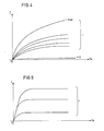
- the excitation current 1 of the coupler can then vary according to the curves of FIG. 4, or the internal impedance of the alternator is adapted to the load, or the excitation current I of the coupler can vary according to a curve of the Figure 5 where the internal impedance of the alternator is large in front of the load.
- the derivative of the excitation current 1 with respect to the input speed V e is greater than 0 (dl / dV e > 0).
- the transmitted torque C T may be increased and the differential speed between the input V e and the output V s of the coupler will be reduced, but it will never be canceled.
- the originality of the system lies in particular in the procedure for switching from the conventional sliding phase of the coupler to a geared phase without sliding.
- control unit 13 When the control unit 13 has given the maximum excitation current i to the inductor 4 of the coupler, and the sliding speed V d becomes less than a predetermined value; the control assembly 13 then emits a brief order to cut the engine torque, by removing the supply of said engine.
- the magnetomotive force of the inductor 4 can then be considerably reduced, while retaining a sufficient clamping force to transmit the torque without slipping. This is due to the fact that the air gap decreases in a very large proportion, and that the diaphragm spring 3 can have in this operating zone a negative slope.
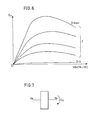
- the excitation current i of the alternation 5 is then restored to a value such that the characteristic of the coupler which is represented in FIG. 6 has a slope dCT / d (Ve-VS), such that this slope corresponds to l critical damping of the oscillating circuits of the transmission. It is thus possible whatever the anterior twist of the transmission, to damp it as quickly as possible.
- the coupler according to the invention is self-regulating by heating the rotor 9, the magnetic permeability of which decreases with temperature, and that it cannot in any case exceed the Curie point. Internal resistance, on the contrary, increases with temperature, and this resistance contributes to the reduction of the transmitted torque C T. It follows from these characteristics, that it is impossible to destroy this coupler by overemphasizing its use. Locking of the sliding coupler is impossible, and this prevents damage and abnormal wear.
- FIG. 7 shows a schematic representation of the mixed clutch according to the invention in which the input speed V e is noted the output speed V s and the torque to be transmitted C t . It should also be noted that the shape of the curves in FIG. 6 depends on the number of poles of the inductor 4 of the coupler, and on the thickness and the diameter of the rotor 9 which is made of mild steel.
- the input shaft 1 carries the flywheel 2.
- the inductor 15 is mounted inside the flywheel, and it is integral in rotation and in translation with said flywheel 2
- the flywheel 2 carries at its end the diaphragm spring 3, which is itself integral in rotation and in translation with the inductor 4.
- the diaphragm spring 3 and inductor 4 assembly thus has freedom in translation towards the inductor 15, when there is a magnetic attraction between these parts.
- a rotor 9 is disposed between the two inductors 4 and 15, and said rotor 9 is mounted idly on a splined shaft 34.
- the splined shaft is supported by two bearings 16 and 17 which are mounted respectively in each of the inductors 4 and 15.
- Each of the bearings 16 and 17 receives a sliding hub 18 and 19, which has grooves 37 cooperating with grooves 36 of the hub 34.
- Each of the bearings 16 and 17 is immobilized in translation relative to the inductors 4 and 15 by means of circlips 40 .
- the sliding hubs 18 and 19 come to rest in translation relative to the bearings 16 and 17 respectively, by means of the end 31 of the sliding hub 18, and of the end 32 of the sliding hub 19, and of the circlips 41.
- the sliding hubs 18 and 19, which can move in translation relative to the splined shaft 34, are limited in this translation by circlips 42 mounted on the shaft 34.
- the axial clearance of these sliding hubs 18 and 19 is limited in the other direction, by the fact that each of their ends 31 and 32 abuts respectively on the ends 27 and 28 of the hub 24 of the rotor 9.
- the axial centering system of the rotor 9 comprises two circular stirrups 20 and 21, which each cooperate with end flanges.
- the stirrup 20 encloses an end flange 22 belonging to the hub 24 of the rotor 9, and an end flange 25 of the hub 18.
- the circular stirrup 21 encloses an end flange 23 of the hub 24 belonging to the rotor 9, and an end flange 26 belonging to the hub 19.
- each notch of the dogs 29 includes an engagement ramp 33.
- the connection between the output shaft 7 and the sliding hubs 18 and 19 takes place in the following manner.
- the bearings 16 and 17 which are secured respectively to the inductors 4 and 15 and whose position is ensured by means of the circlips 40 and 41, engage in the splined shaft 34.
- These sliding hubs 18 and 19 are integral in rotation with the splined shaft 34 by means of the splines 37 of the hubs 18 and 19, and of the splines 36 of the splined shaft 34.
- the limit of the travel of the sliding hubs 18 and 19 is ensured by circlips 42 mounted on the shaft grooved 34.
- the output shaft 7 is mounted inside the grooved shaft 34 and the connection between these two elements is made by means of an elastic element 35. External tongues 38 of the output shaft 7 cooperate with the elastic element 35, which also receives internal tongues 39 of the splined shaft 34.
- the output shaft 7 is integral with the splined shaft 34 while allowing a flexible connection.
- the flywheel 2 and the inductor pole 15 are integral in rotation and translation.
- the flywheel 2 and the diaphragm spring 3 secure the inductor 4 in rotation, but leaves it a freedom of translation of the diaphragm spring 3 towards the inductor 15, when there is magnetic attraction between these parts.
- the diaphragm spring 3 positions the inductor 4 and the inductor 15 with the normal air gap necessary for the operation of the eddy current coupler.
- the circular stirrups 20 and 21, which are in two parts, ensure the equal distribution of the air gap on both sides of the rotor disc 9, as shown in FIGS. 10A and 10B.
- the inductors 4 and 5 are linked in translation by the ball bearings 16 and 17, with the sliding hub 18 and 19. These sliding hubs 18 and 19 can translate on the splined shaft 34, which is provided with stops stops constituted by circlips 42. These circlips 42 serve to stops in the direction of opening of the air gap. Other stops in the closing direction of the air gap are formed by the faces of the hub 24 of the rotor 9, which cooperate with the faces of the ends 31 and 32 of the sliding hubs 18 and 19. The rotor 9 is free to rotate by relative to the splined shaft 34. These stops ensure the transmission of the engine torque by positive contacts between the dog teeth 29 and 30 which belong respectively to the rotor 9, and to the sliding hub 18 and 19. These stops also ensure in coupler operation a precise and symmetrical air gap.
- Figure 9A shows operation with air gap
- Figure 9B shows operation without air gap.
- the dogs 30 of the ends 31 and 32 of the hubs 18 and 19 are positively driven by the dogs 29 of the idler hub 24 of the rotor 9, which receives the engine torque electrodynamically.
- the engagement ramps 33 are such that the electromagnetic clamping force due to the induction between the inductors 4 and 15 cannot tend to close the air gap as long as there is a motor torque transmitted electrodynamically. Whatever the induction caused by the excitation of the coupler, there is a constant relationship between the torque and the attraction until the differential speed between the rotor 9 and the inductors 4 and 15 becomes very low.
- the diaphragm spring 3 will replace the sliding hubs 18 and 19 in the open air gap position.
- FIG. 11 shows the connection between the splined shaft 34 and the output shaft 7.
- the rotor 9 can be either a solid mild steel disc or a mild steel disc incorporating spokes connected in two concentric circles of a good conductive metal to form a squirrel cage similar to that of a flat armature asynchronous motor .
Landscapes
- Engineering & Computer Science (AREA)
- Power Engineering (AREA)
- Dynamo-Electric Clutches, Dynamo-Electric Brakes (AREA)
- Hydraulic Clutches, Magnetic Clutches, Fluid Clutches, And Fluid Joints (AREA)
- Electric Propulsion And Braking For Vehicles (AREA)
Claims (16)
Applications Claiming Priority (4)
| Application Number | Priority Date | Filing Date | Title |
|---|---|---|---|
| FR8419334 | 1984-12-18 | ||
| FR8419334A FR2574883B1 (fr) | 1984-12-18 | 1984-12-18 | Embrayage mixte a friction et courants de foucault et son procede de commande |
| FR8509462A FR2583840B2 (fr) | 1985-06-21 | 1985-06-21 | Embrayage mixte a friction et courants de foucault et son procede de commande |
| FR8509462 | 1985-06-21 |
Publications (2)
| Publication Number | Publication Date |
|---|---|
| EP0185594A1 EP0185594A1 (de) | 1986-06-25 |
| EP0185594B1 true EP0185594B1 (de) | 1990-08-08 |
Family
ID=26224286
Family Applications (1)
| Application Number | Title | Priority Date | Filing Date |
|---|---|---|---|
| EP19850402548 Expired - Lifetime EP0185594B1 (de) | 1984-12-18 | 1985-12-19 | Reibungs- und Wirbelstromverbundkupplung und Verfahren zu ihrer Steuerung |
Country Status (3)
| Country | Link |
|---|---|
| EP (1) | EP0185594B1 (de) |
| DE (1) | DE3579134D1 (de) |
| ES (1) | ES8705591A1 (de) |
Families Citing this family (1)
| Publication number | Priority date | Publication date | Assignee | Title |
|---|---|---|---|---|
| CN1058327C (zh) * | 1994-11-21 | 2000-11-08 | 四川联合大学 | 电涡流快速离合器 |
Family Cites Families (5)
| Publication number | Priority date | Publication date | Assignee | Title |
|---|---|---|---|---|
| CH567675A5 (de) * | 1973-12-18 | 1975-10-15 | Haeussermann August Gmbh | |
| US4147526A (en) * | 1977-12-30 | 1979-04-03 | Owens-Corning Fiberglas Corporation | Glass fiber producing and collecting apparatus |
| DE2920620A1 (de) * | 1979-05-22 | 1980-12-04 | Wilfried Wiesboeck | Elektrisch schaltbare magnet-kombinationskupplung |
| DE2923739A1 (de) * | 1979-06-12 | 1980-12-18 | Max Baermann | Einrichtung zur selbsttaetigen regelung der bremskraft einer durch verschiebbare oder verdrehbare dauermagnete stufenlos schaltbaren wirbelstrom- und/oder friktions-schienenbremse |
| RO78577B1 (ro) * | 1981-09-05 | 1984-04-30 | Institutul De Cercetare Stiintifica Si Inginerie Tehnologica Pentru Industria Electrotehnica | Sistem de actionare electromecanic cu turatie variabila |
-
1985
- 1985-12-17 ES ES550051A patent/ES8705591A1/es not_active Expired
- 1985-12-19 EP EP19850402548 patent/EP0185594B1/de not_active Expired - Lifetime
- 1985-12-19 DE DE8585402548T patent/DE3579134D1/de not_active Expired - Lifetime
Also Published As
| Publication number | Publication date |
|---|---|
| ES550051A0 (es) | 1987-05-01 |
| DE3579134D1 (de) | 1990-09-13 |
| ES8705591A1 (es) | 1987-05-01 |
| EP0185594A1 (de) | 1986-06-25 |
Similar Documents
| Publication | Publication Date | Title |
|---|---|---|
| EP3581416B1 (de) | Getriebevorrichtung, insbesondere für elektrofahrzeug | |
| EP0414782A1 (de) | Stufenlos verstellbares zahnradgetriebe. | |
| FR2800527A1 (fr) | Systeme d'entrainement a groupe electrique, avec boite de vitesses et embrayage | |
| EP4371223A1 (de) | Flugzeugfahrwerk mit einer wirbelstrombasierten magnetischen bremsvorrichtung | |
| FR2572559A1 (fr) | Dispositif d'asservissement electromagnetique | |
| EP0006669A1 (de) | Elektrische Maschine mit veränderlicher Reluktanz | |
| FR2782958A1 (fr) | Systeme d'entrainement pour vehicule automobile avec moteur a combustion interne et moteur electrique | |
| FR2831345A1 (fr) | Machine electrique a defluxage mecanique | |
| EP2233732B1 (de) | Anlassvorrichtung für Verbrennungsmotor, insbesondere von Kraftfahrzeugen | |
| EP0185594B1 (de) | Reibungs- und Wirbelstromverbundkupplung und Verfahren zu ihrer Steuerung | |
| EP2123498A1 (de) | Elektrische Antriebsvorrichtung für Hybridfahrzeug | |
| EP1527509A1 (de) | Elektromagnetische bremse mit einem geschwindigkeitsvervielfacher für ein kraftfahrzeug | |
| EP1878105A1 (de) | Selbstauskoppelnder lüfter für eine elektromagnetische retardierungsvorrichtung | |
| LU88395A1 (fr) | Coupleur magnétique à hystérésis | |
| EP0228326B1 (de) | Kupplungs-Verzögerer | |
| FR2574883A1 (fr) | Embrayage mixte a friction et courants de foucault et son procede de commande | |
| EP2982022B1 (de) | Elektromotor mit niedrigem kurzschlussdrehmoment, antriebsvorrichtung mit mehreren motoren und verfahren zur herstellung solch eines motors | |
| FR2893366A1 (fr) | Demarreur de moteur ayant une roue dentee intermediaire | |
| BE526879A (de) | ||
| EP4046843A1 (de) | Antriebsmodul, hybride unterantriebseinheit eines fahrzeugs und verfahren zum schliessen einer klauenkupplung | |
| FR2828596A1 (fr) | Machine electrique tournante | |
| EP0086119B1 (de) | Elektrischer Getriebemotor der insbesondere für die Verstellung beweglicher Elemente eines Kraftwagens bestimmt ist | |
| EP0642209A1 (de) | Startvorrichtung, für eine Turbine, insbesondere eine Gasturbine | |
| FR2798437A1 (fr) | Systeme d'embrayage pour appareils agricoles | |
| FR2863418A1 (fr) | Ralentisseur electromagnetique comportant un moyen pour connecter des bobines |
Legal Events
| Date | Code | Title | Description |
|---|---|---|---|
| PUAI | Public reference made under article 153(3) epc to a published international application that has entered the european phase |
Free format text: ORIGINAL CODE: 0009012 |
|
| 17P | Request for examination filed |
Effective date: 19851227 |
|
| AK | Designated contracting states |
Kind code of ref document: A1 Designated state(s): BE DE GB IT |
|
| 17Q | First examination report despatched |
Effective date: 19880218 |
|
| GRAA | (expected) grant |
Free format text: ORIGINAL CODE: 0009210 |
|
| AK | Designated contracting states |
Kind code of ref document: B1 Designated state(s): BE DE GB IT |
|
| ITF | It: translation for a ep patent filed | ||
| GBT | Gb: translation of ep patent filed (gb section 77(6)(a)/1977) | ||
| REF | Corresponds to: |
Ref document number: 3579134 Country of ref document: DE Date of ref document: 19900913 |
|
| PLBE | No opposition filed within time limit |
Free format text: ORIGINAL CODE: 0009261 |
|
| STAA | Information on the status of an ep patent application or granted ep patent |
Free format text: STATUS: NO OPPOSITION FILED WITHIN TIME LIMIT |
|
| 26N | No opposition filed | ||
| ITTA | It: last paid annual fee | ||
| PGFP | Annual fee paid to national office [announced via postgrant information from national office to epo] |
Ref country code: GB Payment date: 19931115 Year of fee payment: 9 Ref country code: DE Payment date: 19931115 Year of fee payment: 9 |
|
| PGFP | Annual fee paid to national office [announced via postgrant information from national office to epo] |
Ref country code: BE Payment date: 19931122 Year of fee payment: 9 |
|
| PG25 | Lapsed in a contracting state [announced via postgrant information from national office to epo] |
Ref country code: GB Effective date: 19941219 |
|
| PG25 | Lapsed in a contracting state [announced via postgrant information from national office to epo] |
Ref country code: BE Effective date: 19941231 |
|
| BERE | Be: lapsed |
Owner name: RENAULT VEHICULES INDUSTRIELS Effective date: 19941231 |
|
| GBPC | Gb: european patent ceased through non-payment of renewal fee |
Effective date: 19941219 |
|
| PG25 | Lapsed in a contracting state [announced via postgrant information from national office to epo] |
Ref country code: DE Effective date: 19950901 |