EP1333202A1 - Verfahren und Vorrichtung zur Schaltsteuerung eines Fahrzeuggetriebes - Google Patents
Verfahren und Vorrichtung zur Schaltsteuerung eines Fahrzeuggetriebes Download PDFInfo
- Publication number
- EP1333202A1 EP1333202A1 EP03075145A EP03075145A EP1333202A1 EP 1333202 A1 EP1333202 A1 EP 1333202A1 EP 03075145 A EP03075145 A EP 03075145A EP 03075145 A EP03075145 A EP 03075145A EP 1333202 A1 EP1333202 A1 EP 1333202A1
- Authority
- EP
- European Patent Office
- Prior art keywords
- electric motor
- motor
- synchronization
- speed
- control element
- Prior art date
- Legal status (The legal status is an assumption and is not a legal conclusion. Google has not performed a legal analysis and makes no representation as to the accuracy of the status listed.)
- Withdrawn
Links
- 238000000034 method Methods 0.000 title claims abstract description 11
- 230000005540 biological transmission Effects 0.000 title claims description 19
- 230000008859 change Effects 0.000 claims abstract description 18
- 238000006073 displacement reaction Methods 0.000 claims abstract description 4
- 230000005489 elastic deformation Effects 0.000 claims description 8
- 238000010438 heat treatment Methods 0.000 claims description 3
- 230000001360 synchronised effect Effects 0.000 claims description 3
- 238000004804 winding Methods 0.000 claims description 2
- 238000003032 molecular docking Methods 0.000 description 7
- 230000035939 shock Effects 0.000 description 7
- 230000001133 acceleration Effects 0.000 description 3
- 230000006835 compression Effects 0.000 description 3
- 238000007906 compression Methods 0.000 description 3
- 230000007423 decrease Effects 0.000 description 3
- 230000006870 function Effects 0.000 description 3
- 230000010365 information processing Effects 0.000 description 3
- 230000004044 response Effects 0.000 description 3
- 230000015654 memory Effects 0.000 description 2
- 230000008569 process Effects 0.000 description 2
- 230000009467 reduction Effects 0.000 description 2
- 238000010792 warming Methods 0.000 description 2
- 230000002159 abnormal effect Effects 0.000 description 1
- 238000004364 calculation method Methods 0.000 description 1
- 230000015556 catabolic process Effects 0.000 description 1
- 238000002485 combustion reaction Methods 0.000 description 1
- 238000006731 degradation reaction Methods 0.000 description 1
- 230000006866 deterioration Effects 0.000 description 1
- 238000010586 diagram Methods 0.000 description 1
- 230000001629 suppression Effects 0.000 description 1
- 230000009466 transformation Effects 0.000 description 1
- 230000001131 transforming effect Effects 0.000 description 1
Images
Classifications
-
- F—MECHANICAL ENGINEERING; LIGHTING; HEATING; WEAPONS; BLASTING
- F16—ENGINEERING ELEMENTS AND UNITS; GENERAL MEASURES FOR PRODUCING AND MAINTAINING EFFECTIVE FUNCTIONING OF MACHINES OR INSTALLATIONS; THERMAL INSULATION IN GENERAL
- F16H—GEARING
- F16H61/00—Control functions within control units of change-speed- or reversing-gearings for conveying rotary motion ; Control of exclusively fluid gearing, friction gearing, gearings with endless flexible members or other particular types of gearing
- F16H61/26—Generation or transmission of movements for final actuating mechanisms
- F16H61/28—Generation or transmission of movements for final actuating mechanisms with at least one movement of the final actuating mechanism being caused by a non-mechanical force, e.g. power-assisted
- F16H61/32—Electric motors , actuators or related electrical control means therefor
-
- F—MECHANICAL ENGINEERING; LIGHTING; HEATING; WEAPONS; BLASTING
- F16—ENGINEERING ELEMENTS AND UNITS; GENERAL MEASURES FOR PRODUCING AND MAINTAINING EFFECTIVE FUNCTIONING OF MACHINES OR INSTALLATIONS; THERMAL INSULATION IN GENERAL
- F16H—GEARING
- F16H61/00—Control functions within control units of change-speed- or reversing-gearings for conveying rotary motion ; Control of exclusively fluid gearing, friction gearing, gearings with endless flexible members or other particular types of gearing
- F16H61/26—Generation or transmission of movements for final actuating mechanisms
- F16H61/28—Generation or transmission of movements for final actuating mechanisms with at least one movement of the final actuating mechanism being caused by a non-mechanical force, e.g. power-assisted
- F16H2061/2823—Controlling actuator force way characteristic, i.e. controlling force or movement depending on the actuator position, e.g. for adapting force to synchronisation and engagement of gear clutch
-
- F—MECHANICAL ENGINEERING; LIGHTING; HEATING; WEAPONS; BLASTING
- F16—ENGINEERING ELEMENTS AND UNITS; GENERAL MEASURES FOR PRODUCING AND MAINTAINING EFFECTIVE FUNCTIONING OF MACHINES OR INSTALLATIONS; THERMAL INSULATION IN GENERAL
- F16H—GEARING
- F16H63/00—Control outputs from the control unit to change-speed- or reversing-gearings for conveying rotary motion or to other devices than the final output mechanism
- F16H63/02—Final output mechanisms therefor; Actuating means for the final output mechanisms
- F16H63/30—Constructional features of the final output mechanisms
- F16H63/304—Constructional features of the final output mechanisms the final output mechanisms comprising elements moved by electrical or magnetic force
Definitions
- a power unit comprising a electric motor and means of transformation of movement, connected to an actuating element by a elastically deformable element.
- the element actuation such as a lever or a fork, first move means of synchronization to make the speeds of rotation of the gears from the transmission ratio to engage and primary and secondary trees of the box, then dog clutch means which ensure the securing in rotation of these pinions and gearbox shafts.
- Sensors position are provided on either side of the element elastically deformable and are connected to means information processing who order power to the unit's electric motor driving.
- the electric motor acts on the elastically deformable element which stores mechanical energy (typically by compression of a spring) until the force that this element exerts on the synchronization means exceeds a resistant effort opposed by these means. Then, synchronization being ensured, relaxation of the elastically deformable element causes the dog clutch and engagement of the transmission report.
- mechanical energy typically by compression of a spring
- the object of the invention is in particular to provide a simple, effective and economical solution to these problems.
- It relates to a method and a device for controls that allow rapid gear change, without high effort on synchronization means no violent impact on the end of travel limit stops interconnection, and which are less expensive and less bulky than the technical means earlier.
- Using a low electric motor inertia allows shorter response times, faster variations in speed and a reduction in the electric consumption of the motor, as well as less heating, allowing more high frequency of gear changes.
- the use of a low inertia electric motor also allows to control more precisely what engine, and therefore to use a rigid or high stiffness between the electric motor and the high effortless control element on the synchronization means or violent shock on dog clutch end stops. Suppression of the deformable elastic element used in the prior art results in a reduction of space and cost and allows use from one position sensor, instead of two.
- this process makes it possible to reduce the duration of the gear change in a box of robotic speeds, while avoiding too much effort high on synchronization means and shock violent on the end of travel limit stops interconnection.
- the invention also provides a device for gearshift control in a box of motor vehicle speeds, especially a robotic gearbox, this device comprising at least one electric motor driving a movable control element in the box speeds for synchronization and interconnection of a transmission ratio, and control means of said electric motor, characterized in that the electric motor is a low inertia motor and is connected to the control element by a connection to high stiffness, a position sensor being associated said control element and connected to the means of electric motor control to control the rotational speed of this motor at the position of the control element.
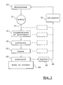
- FIG. 1 a gearshift control device according to the invention, which is used for the engagement of a transmission ratio in a gearbox of motor vehicle, in particular a box of robotic gears, after selecting this gear ratio transmission.
- the engagement of a speed in a motor vehicle gearbox, robotized or not includes a first phase of selection of a corresponding transmission report for example to a transverse movement of a lever gear change in a gear grid, and a second gear shift phase corresponding to a longitudinal displacement of the lever the change of speed in the aforementioned grid and during which the transmission ratio selected is engaged.
- gear rotation speeds of the ratio of selected transmission which usually includes a pinion carried by a primary gearbox shaft speeds, driven in rotation by the motor internal combustion of the motor vehicle, and a pinion carried by the secondary shaft or output of the gearbox, connected by a transmission to the vehicle's drive wheels automobile.
- the travel of the dog clutch means is limited by a limit stop and we try to avoid too violent shocks on this stop, which cause noise and which can cause abnormal wear and degradation of parts in contact.
- the electric motor 12 is connected by its shaft output 14, to means 16 for transforming movement, such as a gearbox gears or the like, connected by means actuators 18 and connecting means 20 to a shift control element 22 in the gearbox 24 of the motor vehicle, this element 22 being or comprising for example a lever movable in pivoting or in translation, such as in particular that a gear shift range of transmission.
- the means 16, 18, 20, 22 connecting the output shaft of the motor 12 to the means of synchronization and interconnection in the box 24 gears constitute a high stiffness connection which has a small elastic deformation stroke, at during a gear change, less than the stroke synchronization means and that of the means interconnection.
- a control signal is sent by means 30 of information processing means 10 power supply to motor 12, which is powered by a direct current of intensity determined, preferably corresponding to a speed maximum rotation of the motor 12.
- the element of command 22 is then driven at maximum speed for moving a walkman or a sleeve in the gearbox, this walkman or sleeve coming successively to act on the means of synchronization, then on the dog clutch means.
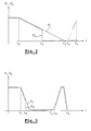
- the solid line curve represents the variation of the speed of rotation V1 of the motor 12 as a function of time t
- the cross curve represents the variation of the speed V2 of the walkman or sleeve as a function of time t, in a passage of speed.
- the two curves V1 and V2 are represented with the same maximum values and the same minimum values even if, in reality, one of these speeds is a speed of rotation and the other a speed of translation.
- the speed of rotation of the motor 12 is controlled according to signal 28 from position of the control element 22 supplied by the sensor 26 to means 30 for processing information, and we plan to slow down significantly the speed V1 of the front motor 12 docking of the player or the sleeve on the means synchronization.
- the position of the docking point synchronization means being known, for example calculation and / or by learning as indicated in the Applicant's previous patent applications, we controls at time t1 the slowing down of the motor 12 so as to arrive at time t2 at the docking point on the means of synchronization with a speed about 0.1 m / s for example, which is very clearly lower than the maximum speed of movement of the player or sleeve, to reduce to a value admissible the effort applied to the means of synchronization and thus not to damage them.
- the duration t2-t3 represents the duration of the synchronization.
- the speeds of rotation of the gears from the transmission ratio to engage and primary and secondary trees of the gearboxes are equal and the dog clutch can take place.
- the restart of the motor 12 whose speed V1 increases very quickly to its maximum value or up to the vicinity of this maximum value before to be reduced again to zero at time t5, which corresponds to the end of the dog clutch, determined by an end stop.
Landscapes
- Engineering & Computer Science (AREA)
- General Engineering & Computer Science (AREA)
- Mechanical Engineering (AREA)
- Gear-Shifting Mechanisms (AREA)
- Connection Of Motors, Electrical Generators, Mechanical Devices, And The Like (AREA)
Applications Claiming Priority (2)
| Application Number | Priority Date | Filing Date | Title |
|---|---|---|---|
| FR0200746A FR2835030B1 (fr) | 2002-01-22 | 2002-01-22 | Procede et dispositif de commande du passage des vitesses dans une boite de vitesses de vehicule automobile |
| FR0200746 | 2002-01-22 |
Publications (1)
| Publication Number | Publication Date |
|---|---|
| EP1333202A1 true EP1333202A1 (de) | 2003-08-06 |
Family
ID=8871370
Family Applications (1)
| Application Number | Title | Priority Date | Filing Date |
|---|---|---|---|
| EP03075145A Withdrawn EP1333202A1 (de) | 2002-01-22 | 2003-01-17 | Verfahren und Vorrichtung zur Schaltsteuerung eines Fahrzeuggetriebes |
Country Status (2)
| Country | Link |
|---|---|
| EP (1) | EP1333202A1 (de) |
| FR (1) | FR2835030B1 (de) |
Cited By (5)
| Publication number | Priority date | Publication date | Assignee | Title |
|---|---|---|---|---|
| EP1701067A1 (de) * | 2005-03-11 | 2006-09-13 | Zf Friedrichshafen Ag | Verfahren zur Steuerung von Schaltabläufen in einem automatisierten Schaltgetriebe in Vorgelegebauweise |
| WO2007132106A1 (fr) * | 2006-05-16 | 2007-11-22 | Peugeot Citroën Automobiles SA | Procédé de pilotage d'un dispositif d'accouplement de deux crabots |
| FR2904674A1 (fr) * | 2006-08-01 | 2008-02-08 | Peugeot Citroen Automobiles Sa | Procede de determination des positions de debut et de fin d'emboitement d'un crabot et boite de vitesses estimant une position de debut et de fin de crabotage au passage d'un rapport |
| EP1564449A3 (de) * | 2004-02-10 | 2009-08-05 | AISIN AI Co., Ltd. | Vorrichtung zur Steuerung des automatischen Schaltvorgang in einem Fahrzeug |
| EP2072864A3 (de) * | 2007-12-14 | 2013-08-21 | AISIN AI Co., Ltd. | Steuervorrichtung in einer getriebeartigen Übertragungsvorrichtung |
Citations (15)
| Publication number | Priority date | Publication date | Assignee | Title |
|---|---|---|---|---|
| GB1112503A (en) * | 1965-11-25 | 1968-05-08 | Intomatic Basel A G | Gear-changing apparatus |
| DE3329801A1 (de) * | 1983-08-18 | 1985-02-28 | Wabco Westinghouse Fahrzeugbremsen GmbH, 3000 Hannover | Synchronisiertes getriebe |
| DE19637001A1 (de) * | 1995-09-12 | 1997-03-13 | Luk Getriebe Systeme Gmbh | Kraftfahrzeug mit einer Einrichtung zur Betätigung des Drehmomentübertragungssystems und des Getriebes |
| DE19900852A1 (de) * | 1998-01-16 | 1999-07-22 | Atlas Fahrzeugtechnik Gmbh | Getriebe mit einer Einrichtung zur Betätigung des Drehmomentenübertragungssystems und der Getriebebetätigungselemente |
| WO1999056040A1 (fr) * | 1998-04-28 | 1999-11-04 | Valeo | Actionneur electromecanique pour boite de vitesses mecanique |
| DE19914394A1 (de) * | 1998-12-28 | 2000-06-29 | Bosch Gmbh Robert | Verfahren und Vorrichtung zur Steuerung eines Schaltmechanismus bei einem automatisierten Schaltgetriebe |
| DE19917215A1 (de) * | 1999-04-16 | 2000-10-19 | Mannesmann Sachs Ag | Elektromotorische Stellanordnung für eine automatisierte Getriebe-Kupplungs-Baugruppe eines Fahrzeugs |
| EP1055847A2 (de) * | 1999-05-25 | 2000-11-29 | AISIN AI Co., Ltd. | Schalteinrichtung für Getriebe |
| WO2001045237A1 (en) * | 1999-12-14 | 2001-06-21 | Delphi Technologies, Inc. | Brushless motor with reduced rotor inertia |
| DE10110898A1 (de) * | 2000-03-22 | 2001-09-27 | Luk Lamellen & Kupplungsbau | Verfahren und Vorrichtung hinsichtlich eines automatisierten Schaltgetriebes |
| WO2001073321A1 (de) * | 2000-03-24 | 2001-10-04 | Siemens Aktiengesellschaft | Steuerung für ein automatisiertes schaltgetriebe |
| EP1178246A1 (de) * | 2000-08-01 | 2002-02-06 | Renault | Getriebesteuerungsvorrichtung und -verfahren |
| FR2812706A1 (fr) * | 2000-08-01 | 2002-02-08 | Renault | Dispositif et procede de commande d'une boite de vitesses |
| DE10148085A1 (de) * | 2000-10-20 | 2002-05-02 | Luk Lamellen & Kupplungsbau | Kraftfahrzeug mit Getriebe sowie Verfahren zum Betreiben eines Kraftfahrzeuges |
| EP1271010A1 (de) * | 2001-06-19 | 2003-01-02 | Getrag Ford Transmissions GmbH | Automatisierter Antriebsstrang für ein Kraftfahrzeug und Verfahren zum Einlegen eines Ganges |
-
2002
- 2002-01-22 FR FR0200746A patent/FR2835030B1/fr not_active Expired - Lifetime
-
2003
- 2003-01-17 EP EP03075145A patent/EP1333202A1/de not_active Withdrawn
Patent Citations (15)
| Publication number | Priority date | Publication date | Assignee | Title |
|---|---|---|---|---|
| GB1112503A (en) * | 1965-11-25 | 1968-05-08 | Intomatic Basel A G | Gear-changing apparatus |
| DE3329801A1 (de) * | 1983-08-18 | 1985-02-28 | Wabco Westinghouse Fahrzeugbremsen GmbH, 3000 Hannover | Synchronisiertes getriebe |
| DE19637001A1 (de) * | 1995-09-12 | 1997-03-13 | Luk Getriebe Systeme Gmbh | Kraftfahrzeug mit einer Einrichtung zur Betätigung des Drehmomentübertragungssystems und des Getriebes |
| DE19900852A1 (de) * | 1998-01-16 | 1999-07-22 | Atlas Fahrzeugtechnik Gmbh | Getriebe mit einer Einrichtung zur Betätigung des Drehmomentenübertragungssystems und der Getriebebetätigungselemente |
| WO1999056040A1 (fr) * | 1998-04-28 | 1999-11-04 | Valeo | Actionneur electromecanique pour boite de vitesses mecanique |
| DE19914394A1 (de) * | 1998-12-28 | 2000-06-29 | Bosch Gmbh Robert | Verfahren und Vorrichtung zur Steuerung eines Schaltmechanismus bei einem automatisierten Schaltgetriebe |
| DE19917215A1 (de) * | 1999-04-16 | 2000-10-19 | Mannesmann Sachs Ag | Elektromotorische Stellanordnung für eine automatisierte Getriebe-Kupplungs-Baugruppe eines Fahrzeugs |
| EP1055847A2 (de) * | 1999-05-25 | 2000-11-29 | AISIN AI Co., Ltd. | Schalteinrichtung für Getriebe |
| WO2001045237A1 (en) * | 1999-12-14 | 2001-06-21 | Delphi Technologies, Inc. | Brushless motor with reduced rotor inertia |
| DE10110898A1 (de) * | 2000-03-22 | 2001-09-27 | Luk Lamellen & Kupplungsbau | Verfahren und Vorrichtung hinsichtlich eines automatisierten Schaltgetriebes |
| WO2001073321A1 (de) * | 2000-03-24 | 2001-10-04 | Siemens Aktiengesellschaft | Steuerung für ein automatisiertes schaltgetriebe |
| EP1178246A1 (de) * | 2000-08-01 | 2002-02-06 | Renault | Getriebesteuerungsvorrichtung und -verfahren |
| FR2812706A1 (fr) * | 2000-08-01 | 2002-02-08 | Renault | Dispositif et procede de commande d'une boite de vitesses |
| DE10148085A1 (de) * | 2000-10-20 | 2002-05-02 | Luk Lamellen & Kupplungsbau | Kraftfahrzeug mit Getriebe sowie Verfahren zum Betreiben eines Kraftfahrzeuges |
| EP1271010A1 (de) * | 2001-06-19 | 2003-01-02 | Getrag Ford Transmissions GmbH | Automatisierter Antriebsstrang für ein Kraftfahrzeug und Verfahren zum Einlegen eines Ganges |
Cited By (8)
| Publication number | Priority date | Publication date | Assignee | Title |
|---|---|---|---|---|
| EP1564449A3 (de) * | 2004-02-10 | 2009-08-05 | AISIN AI Co., Ltd. | Vorrichtung zur Steuerung des automatischen Schaltvorgang in einem Fahrzeug |
| EP1701067A1 (de) * | 2005-03-11 | 2006-09-13 | Zf Friedrichshafen Ag | Verfahren zur Steuerung von Schaltabläufen in einem automatisierten Schaltgetriebe in Vorgelegebauweise |
| US7430936B2 (en) | 2005-03-11 | 2008-10-07 | Zf Friedrichshafen Ag | Method for the control of operational sequencing in an automatic transmission of auxiliary construction |
| WO2007132106A1 (fr) * | 2006-05-16 | 2007-11-22 | Peugeot Citroën Automobiles SA | Procédé de pilotage d'un dispositif d'accouplement de deux crabots |
| FR2901334A1 (fr) * | 2006-05-16 | 2007-11-23 | Peugeot Citroen Automobiles Sa | Procede de pilotage d'un dispositif d'accouplement de deux crabots |
| FR2904674A1 (fr) * | 2006-08-01 | 2008-02-08 | Peugeot Citroen Automobiles Sa | Procede de determination des positions de debut et de fin d'emboitement d'un crabot et boite de vitesses estimant une position de debut et de fin de crabotage au passage d'un rapport |
| EP1887258A1 (de) * | 2006-08-01 | 2008-02-13 | Peugeot Citroën Automobiles S.A. | Verfahren zur Bestimmung der Anfangs- und Endposition des Einrastens der Klaue einer Klauenkupplung und Getriebe, das die Anfangs- und Endposition der Klauenkupplung beim Schalten abschätzt |
| EP2072864A3 (de) * | 2007-12-14 | 2013-08-21 | AISIN AI Co., Ltd. | Steuervorrichtung in einer getriebeartigen Übertragungsvorrichtung |
Also Published As
| Publication number | Publication date |
|---|---|
| FR2835030B1 (fr) | 2005-05-06 |
| FR2835030A1 (fr) | 2003-07-25 |
Similar Documents
| Publication | Publication Date | Title |
|---|---|---|
| EP1453694B1 (de) | Kraftübertragungsvorrichtung mit mindestens zwei planetengetriebezügen | |
| EP2081808B1 (de) | Verfahren und vorrichtung zur kompensation von drehmomentverlust des antriebsaggregats eines hybridfahrzeuges während eines gangwechsels | |
| FR2625278A1 (fr) | Actionneur pour dispositif de mise en prise a friction | |
| FR2892471A1 (fr) | Procede de demarrage d'un moteur thermique de vehicule hybride | |
| FR2956637A1 (fr) | Procede de gestion d'un systeme d'entrainement pour vehicule automobile | |
| EP3129683B1 (de) | Verfahren zur steuerung eines gangschaltaktuators und entsprechender schaltaktuator | |
| FR2800527A1 (fr) | Systeme d'entrainement a groupe electrique, avec boite de vitesses et embrayage | |
| EP1567766A1 (de) | Antriebssystem für verbrennungsmotor und starter-generator | |
| FR2523525A1 (fr) | Systeme d'entrainement a recuperation d'une charge a des vitesses variables | |
| WO2012042137A1 (fr) | Groupe motopropulseur hybride a arbres d'entree coaxiaux et procede de commande correspondant | |
| EP1896281A2 (de) | Verfahren zur steuerung der kopplung oder entkopplung des ersten und des zweiten motors eines parallel-hybridmotor-stromaggregats | |
| FR2835030A1 (fr) | Procede et dispositif de commande du passage des vitesses dans une boite de vitesses de vehicule automobile | |
| FR2674928A1 (fr) | Dispositif de synchronisation des vitesses angulaires des arbres d'une boite de vitesses. | |
| FR2887496A1 (fr) | Procede pour piloter le couplage ou le decouplage des deux moteurs d'un groupe motopropulseur hybride parallele | |
| WO2008029042A1 (fr) | Procede de pilotage d'un dispositif d'accouplement de deux crabots, a temps de crabotage reduit | |
| FR2821124A1 (fr) | Procede de commande d'un dispositif demarreur d'un moteur thermique, du type a deux demarreurs et dispositif pour la mise en oeuvre de ce procede | |
| EP1640203B1 (de) | System zur Steuerung eines Hybridfahrzeugs | |
| EP0185594B1 (de) | Reibungs- und Wirbelstromverbundkupplung und Verfahren zu ihrer Steuerung | |
| FR2864584A1 (fr) | Systeme de demarrage de moteur | |
| FR2796991A1 (fr) | Demerreur de vehicule automobile muni d'un element elastique d'engrenement de raideur elastique non lineaire | |
| FR2897134A1 (fr) | Groupe motopropulseur hybride optimise pour l'engagement de la premiere vitesse et de la marche arriere | |
| FR2990388A3 (fr) | "installation de reglage manuel du couple resistant d'un moteur electrique de traction comportant un dispositif de commande sequentielle du couple resistant" | |
| EP1178246A1 (de) | Getriebesteuerungsvorrichtung und -verfahren | |
| WO2008074955A1 (fr) | Procede de changement de rapport a crabotage optimise dans une boite de vitesses, et boite de vitesses notamment pour vehicule hybride | |
| FR2969221A1 (fr) | Demarreur a engrenement permanent equipe d'un systeme d'accouplement de la roue d'entrainement au rotor du moteur du demarreur |
Legal Events
| Date | Code | Title | Description |
|---|---|---|---|
| PUAI | Public reference made under article 153(3) epc to a published international application that has entered the european phase |
Free format text: ORIGINAL CODE: 0009012 |
|
| 17P | Request for examination filed |
Effective date: 20030117 |
|
| AK | Designated contracting states |
Designated state(s): AT BE BG CH CY CZ DE DK EE ES FI FR GB GR HU IE IT LI LU MC NL PT SE SI SK TR |
|
| AX | Request for extension of the european patent |
Extension state: AL LT LV MK RO |
|
| 17Q | First examination report despatched |
Effective date: 20031217 |
|
| AKX | Designation fees paid |
Designated state(s): DE IT |
|
| STAA | Information on the status of an ep patent application or granted ep patent |
Free format text: STATUS: THE APPLICATION HAS BEEN WITHDRAWN |
|
| 18W | Application withdrawn |
Effective date: 20040701 |