EP0185599B1 - Kühlung des Abströmendes einer Turbinenschaufel - Google Patents
Kühlung des Abströmendes einer Turbinenschaufel Download PDFInfo
- Publication number
- EP0185599B1 EP0185599B1 EP85630176A EP85630176A EP0185599B1 EP 0185599 B1 EP0185599 B1 EP 0185599B1 EP 85630176 A EP85630176 A EP 85630176A EP 85630176 A EP85630176 A EP 85630176A EP 0185599 B1 EP0185599 B1 EP 0185599B1
- Authority
- EP
- European Patent Office
- Prior art keywords
- airfoil
- trailing edge
- inch
- side wall
- thickness
- Prior art date
- Legal status (The legal status is an assumption and is not a legal conclusion. Google has not performed a legal analysis and makes no representation as to the accuracy of the status listed.)
- Expired
Links
Images
Classifications
-
- F—MECHANICAL ENGINEERING; LIGHTING; HEATING; WEAPONS; BLASTING
- F01—MACHINES OR ENGINES IN GENERAL; ENGINE PLANTS IN GENERAL; STEAM ENGINES
- F01D—NON-POSITIVE DISPLACEMENT MACHINES OR ENGINES, e.g. STEAM TURBINES
- F01D5/00—Blades; Blade-carrying members; Heating, heat-insulating, cooling or antivibration means on the blades or the members
- F01D5/12—Blades
- F01D5/14—Form or construction
- F01D5/18—Hollow blades, i.e. blades with cooling or heating channels or cavities; Heating, heat-insulating or cooling means on blades
- F01D5/186—Film cooling
Definitions
- This invention relates to airfoils, and more particularly to cooling the trailing edge region of airfoils.
- Airfoils constructed with spanwise cavities and passageways for carrying coolant fluid therethrough are well known in the art. Cooling fluid is brought into the cavities; and some of the fluid is ejected via holes in the airfoil walls to film cool the external surface of the airfoil.
- the trailing edge region of airfoils is generally difficult to cool because the cooling air is hotter when it arrives at the trailing edge since it has been used to cool other portions of the airfoil.
- the relative thinness of the trailing edge region makes it more susceptible to damage due to overheating and thermal stresses.
- Each partition has an upstream portion with straight, parallel side walls, and a downstream portion which tapers to substantially a point at the outlet of the slot.
- the transverse channels therefore, include a straight upstream portion and a diffusing downstream portion.
- the object is to form a continuous sheet of cooling air which remains attached to the exposed inside surface of the suction side wall downstream of the slot outlet.
- Other patents showing spanwise trailing edge region slots and cut back pressure side walls are US-A-3,885,609; US-A-3,930,748; and US-A.-4,229,140.
- the cut back portion of the trailing edge is film cooled by cooling air exiting from a slot within the trailing edge region.
- the cooling air exiting the slot forms a film on the exposed internal surface of the suction side wall down-stream of the slot.
- decay of the film as it moves further downstream from the slot outlet must be minimized to the extent that the film is still sufficiently effective at the trailing edge. The longer the cut back distance x the more difficult it is to maintain film cooling effectiveness over the full length of the cut back.
- the object of the present invention is to provide a turbine blade airfoil having a trailing edge region cooling configuration wherein a lower coolant flow rate can provide cooling equivalent to the cooling provided by higher flow rates of the prior art, or wherein the pressure side cut back length in the trailing edge region may be increased without increasing the coolant flow rate.
- a lower coolant flow rate can provide cooling equivalent to the cooling provided by higher flow rates of the prior art, or wherein the pressure side cut back length in the trailing edge region may be increased without increasing the coolant flow rate.
- the airfoil has a spanwise cooling air cavity and a spanwise trailing edge slot in fluid communication with the cavity, the slot outlet being disposed at the cut back downstream edge of the pressure side wall, the edge having a thickness t.
- Down- stream extending partitions are disposed within the slot and extend downstream thereof to divide the slot into a plurality of channels, each channel having a width s at the slot outlet.
- the channels discharge cooling air over the exposed back surface of the suction sidewall, each channel having a throat upstream of the slot outlet.
- the ratio t/s is less than or equal to 0.7.
- P is a dimensionless air flow parameter directly proportional to the cut back distance and inversely proportional to the cooling air flow rate. Higher values of P mean greater cut back distances and less air flow for equivalent film cooling effectiveness.
- Film cooling effectiveness is the difference between the main gas stream temperature and the temperature of the coolant film, divided by the difference between the main gas stream temperature and the coolant temperature at the slot exit.
- High film cooling effectiveness can be maintained over significantly longer cut back distances using significantly less cooling air when the ratio t/s is low (preferably less than 0.7, most preferably less than 0.6). More specifically, a prior art airfoil having a t/s ratio of 1.2 has a value of P only one fifth the value for an airfoil having a t/s ratio of 0.7, at the same level of film cooling effectiveness.
- the present invention is particularly useful for airfoils with thin trailing edges (i.e. 1 mm thick, or less). Cooling problems increase as the trailing edge thickness is reduced. In the prior art it was felt that cut back distances could not be further increased and trailing edge thickness could not be further reduced because cooling flow rates would have to be increased excessively to assure adequate cooling of the full length of the cut back portion.
- the cooling improvements provided by t/s ratios of 0.7 and less not only allow longer cut backs (for improved aerodynamics performance), but reduce the coolant flow requirements to cool the longer cut back portion of the trailing edge region. Furthermore, increasing the cut back distance not only provides greater airfoil thickness at the trailing edge slot outlet (thereby allowing the t/s ratio to be decreased), it results in reduced gas stream pressure at the slot outlet such that larger slots can be used without increasing and preferably, decreasing the coolant flow rate. Larger slots are easier to fabricate and, if large enough, may be castable.
- the air flow through each channel within the slot is metered upstream of the slot outlet.
- the dimension s at the slot outlet may then be increased to the extent permitted by the thickness of the airfoil at that location to reduce the t/s ratio without increasing coolant flow rate.
- the cut back distance for prior art airfoils operating in gas path temperatures above about 1200°C has been maintained well below 2,5 mm.
- the present invention permits cutbacks of at least 2,5 mm in such environments, and with reduced coolant flow.
- the trailing edge thickness of airfoils constructed in accordance with the teachings of the present invention may be made as small as 0,9 mm or less. This improves airfoil aerodynamics, and can be accomplished only because the cut back distance can be increased, thereby providing additional material thickness at the slot outlet (where s is measured). This allows the value of s to be increased so the airfoil may be constructed with a t/s ratio of 0.7 or less.
- Short cut back distances used in the prior art at these high gas temperatures meant reduced airfoil thickness at the slot outlet and the requirement for a thicker trailing edge region and trailing edge to compensate.
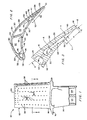
- the gas turbine engine turbine blade of Figure 1 which is generally represented by the reference numeral 10.
- the blade 10 includes an airfoil 12, a root 14, and a platform 16.
- the airfoil 12 has a base 18 and a tip 20.
- the spanwise or longitudinal direction is in the direction of the length of the airfoil, which is from its base 18 to its tip 20.
- the airfoil is a single piece casting.
- the invention is particularly advantageous for hollow, one piece cast blades, it is not intended to be limited thereto.
- the airfoil 12 includes a pressure side wall 22 and a suction side wall 24.
- the inside wall surfaces 26, 28 of the pressure and suction side walls 22, 24, respectively, along with the spanwise partitions 30 extending between them define spanwise central cooling air passageways 32, 33 which extend substantially the full length of the airfoil 12.
- the cavities 32, 33 are fed cooling air via a pair of channels 34 ( Figure 1) extending longitudinally through the root 14 and in communication with the cavities.
- the cavity 32 feeds a spanwise extending leading edge cavity 35 via a plurality of interconnecting passages 36. Cooling air from the leading edge cavity 35 exits the airfoil via a plurality of holes 38 to provide convective and film cooling of the airfoil leading edge.
- the remainder of the cooling air from the cavity 32 exits the airfoil via a plurality of passages 48 and film cools the walls 22, 24.
- the central cavity 33 communicates with two additional spanwise extending cavities 40, 41 in the trailing edge region 42 of the airfoil via a plurality of interconnecting passages 44, 46.
- a portion of the air from the cavity 33 exits the airfoil and film cools the outer surfaces thereof via passages 50.
- the remainder enters the cavity 40 via the interconnecting passages 44, some of which exits the airfoil via passages 52, the remainder flowing into the cavity 41. Cooling air from the cavity 41 passes from the airfoil via a spanwise extending slot 54 defined between the pressure and suction side wall internal surfaces 26, 28, respectively.
- the slot 54 is divided into a plurality of downstream extending channels 56 by means of a plurality of spanwise spaced apart, downstream extending partitions 58.
- the upstream ends 59 of each partition 58 is rounded to minimize turbulence.
- Each partition extends from the cavity 41 and tapers in a down- stream direction to its downstream most end 60 at the trailing edge 61 of the airfoil 12.
- the channels 56 thus diffuse in a spanwise direction from a throat 63 at their upstream ends, to their downstream ends at the trailing edge 61.
- the coolant flow rate through each channel 56 is metered at the throat 63.
- the pressure side wall 22 is cut back a distance x from the trailing edge 61 such that the trailing edge is defined solely by the downstream most end of the suction side wall 24.
- the cut back exposes the portion 65 of the inside or back surface 28 of the suction side wall 24, down- stream of the pressure side wall end 66, to the hot gases in the engine flow path.
- the trailing edge 61 has a diameter d.
- the thickness of the trailing edge is d.
- the thickness t of the downstream edge 66 of the pressure side wall 22, which is at the outlet of the trailing edge slot 54, is preferably as small as possible.
- a practical state of the art as- cast minimum for t is about 0,25 mm.
- a throat width A as small as 0,35 mm can be made with state of the art casting technology.
- Throat width A is measured in a plane perpendicular to the spanwise direction.
- the slot outlet width s is measured perpendicular to the slot suction side wall 28, also in a plane pendicularto the spanwise direction and is the distance, from that internal suction side wall to the internal pressure side wall 26 at the slot outlet.
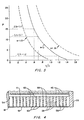
- the ratio t/s is plotted against P a dimensionless flow parameter, which is directly proportional to the cut back distance x.
- P is plotted against t/s for several values of e, the film cooling effectiveness.
- the graph shows that the value of e can remain constant as x increases, if the value of the ratio t/s is decreased.
- a film cooling effectiveness of 0.9 a reduction in the value of t/s from 1.2 (prior art) to 0.7, results in an increase in P of from about 2 to 10. This means that if all other parameters affecting P could be held constant, the cut back distance x could be increased by a factor of 5 without a loss of film cooling effectiveness over the length of the cut back portion.
- the coolant flow rate could be reduced and the cut back distance increased, some lesser amount.
- cut back distances of at least 2,5 mm, preferably 3,3 mm and most preferably greater than 5 mm can be used while decreasing the amount of coolant needed to cool the trailing edge to 30% or less of the total blade coolant supply.
- the magnitude of s is limited by the minimum permissible thickness of the suction side wall 24 at the slot outlet.
- the suction side wall is thinnest at the slot outlet, and then increases to a thickness d at the trailing edge 61. Since the slot throat at 63 is used to meter the flow through the slot, the dimension s will be greater than dimension A. The greater the distance x the thicker the airfoil at the slot outlet. This, in turn, permits fabricating the airfoil with a larger slot outlet dimension s.
- t is made as small as possible consistent with strength requirements, and s is made as large as possible, also consistent with strength requirements, such that t/s is less than or equal to 0.7.
- the channels 56 diffuse from their throat 63 to the slot outlet when viewed in a cross section perpendicular to the spanwise direction. This diffusion in and of itself improves cooling capabilities of the present invention.
- a turbine airfoil made in accordance with the teachings of the present invention and which operated successfully in a gas stream having a temperature of about 1430°C had the following approximate dimensions:
Landscapes
- Engineering & Computer Science (AREA)
- Mechanical Engineering (AREA)
- General Engineering & Computer Science (AREA)
- Turbine Rotor Nozzle Sealing (AREA)
Claims (8)
Applications Claiming Priority (2)
| Application Number | Priority Date | Filing Date | Title |
|---|---|---|---|
| US06/685,263 US4601638A (en) | 1984-12-21 | 1984-12-21 | Airfoil trailing edge cooling arrangement |
| US685263 | 1984-12-21 |
Publications (2)
| Publication Number | Publication Date |
|---|---|
| EP0185599A1 EP0185599A1 (de) | 1986-06-25 |
| EP0185599B1 true EP0185599B1 (de) | 1989-12-06 |
Family
ID=24751436
Family Applications (1)
| Application Number | Title | Priority Date | Filing Date |
|---|---|---|---|
| EP85630176A Expired EP0185599B1 (de) | 1984-12-21 | 1985-10-31 | Kühlung des Abströmendes einer Turbinenschaufel |
Country Status (5)
| Country | Link |
|---|---|
| US (1) | US4601638A (de) |
| EP (1) | EP0185599B1 (de) |
| JP (2) | JPS61155601A (de) |
| DE (1) | DE3574609D1 (de) |
| IL (1) | IL76565A (de) |
Cited By (1)
| Publication number | Priority date | Publication date | Assignee | Title |
|---|---|---|---|---|
| US11634994B2 (en) | 2021-05-19 | 2023-04-25 | Rolls-Royce Plc | Nozzle guide vane |
Families Citing this family (93)
| Publication number | Priority date | Publication date | Assignee | Title |
|---|---|---|---|---|
| US4770608A (en) * | 1985-12-23 | 1988-09-13 | United Technologies Corporation | Film cooled vanes and turbines |
| US4672727A (en) * | 1985-12-23 | 1987-06-16 | United Technologies Corporation | Method of fabricating film cooling slot in a hollow airfoil |
| US5102299A (en) * | 1986-11-10 | 1992-04-07 | The United States Of America As Represented By The Secretary Of The Air Force | Airfoil trailing edge cooling configuration |
| US4863348A (en) * | 1987-02-06 | 1989-09-05 | Weinhold Wolfgang P | Blade, especially a rotor blade |
| US6139258A (en) * | 1987-03-30 | 2000-10-31 | United Technologies Corporation | Airfoils with leading edge pockets for reduced heat transfer |
| US4859147A (en) * | 1988-01-25 | 1989-08-22 | United Technologies Corporation | Cooled gas turbine blade |
| GB2227965B (en) * | 1988-10-12 | 1993-02-10 | Rolls Royce Plc | Apparatus for drilling a shaped hole in a workpiece |
| FR2648517B1 (fr) * | 1989-06-14 | 1994-04-01 | Snecma | Propulseur combine turbofusee statoreacteur a rechauffe et son procede de fonctionnement |
| US5184459A (en) * | 1990-05-29 | 1993-02-09 | The United States Of America As Represented By The Secretary Of The Air Force | Variable vane valve in a gas turbine |
| US5405242A (en) * | 1990-07-09 | 1995-04-11 | United Technologies Corporation | Cooled vane |
| US5156526A (en) * | 1990-12-18 | 1992-10-20 | General Electric Company | Rotation enhanced rotor blade cooling using a single row of coolant passageways |
| US5220787A (en) * | 1991-04-29 | 1993-06-22 | Aerojet-General Corporation | Scramjet injector |
| US5246340A (en) * | 1991-11-19 | 1993-09-21 | Allied-Signal Inc. | Internally cooled airfoil |
| US5660524A (en) * | 1992-07-13 | 1997-08-26 | General Electric Company | Airfoil blade having a serpentine cooling circuit and impingement cooling |
| US5356265A (en) * | 1992-08-25 | 1994-10-18 | General Electric Company | Chordally bifurcated turbine blade |
| US5368441A (en) * | 1992-11-24 | 1994-11-29 | United Technologies Corporation | Turbine airfoil including diffusing trailing edge pedestals |
| US5288207A (en) * | 1992-11-24 | 1994-02-22 | United Technologies Corporation | Internally cooled turbine airfoil |
| US5688104A (en) * | 1993-11-24 | 1997-11-18 | United Technologies Corporation | Airfoil having expanded wall portions to accommodate film cooling holes |
| US5378108A (en) * | 1994-03-25 | 1995-01-03 | United Technologies Corporation | Cooled turbine blade |
| US5503529A (en) * | 1994-12-08 | 1996-04-02 | General Electric Company | Turbine blade having angled ejection slot |
| US5498133A (en) * | 1995-06-06 | 1996-03-12 | General Electric Company | Pressure regulated film cooling |
| US5711650A (en) * | 1996-10-04 | 1998-01-27 | Pratt & Whitney Canada, Inc. | Gas turbine airfoil cooling |
| JP3615907B2 (ja) | 1997-06-12 | 2005-02-02 | 三菱重工業株式会社 | ガスタービン冷却翼 |
| JPH1193694A (ja) * | 1997-09-18 | 1999-04-06 | Toshiba Corp | ガスタービンプラント |
| US6004100A (en) * | 1997-11-13 | 1999-12-21 | United Technologies Corporation | Trailing edge cooling apparatus for a gas turbine airfoil |
| US5975851A (en) * | 1997-12-17 | 1999-11-02 | United Technologies Corporation | Turbine blade with trailing edge root section cooling |
| GB2345942B (en) * | 1998-12-24 | 2002-08-07 | Rolls Royce Plc | Gas turbine engine internal air system |
| US6190120B1 (en) * | 1999-05-14 | 2001-02-20 | General Electric Co. | Partially turbulated trailing edge cooling passages for gas turbine nozzles |
| US6241466B1 (en) | 1999-06-01 | 2001-06-05 | General Electric Company | Turbine airfoil breakout cooling |
| EP1057565B1 (de) | 1999-06-02 | 2006-03-29 | General Electric Company | Verfahren zur Verminderung der Wandstärke nach dem Giessen einen Turbinenschaufels mittels Funkenerosionsbearbeitung |
| US6179565B1 (en) | 1999-08-09 | 2001-01-30 | United Technologies Corporation | Coolable airfoil structure |
| US6234754B1 (en) | 1999-08-09 | 2001-05-22 | United Technologies Corporation | Coolable airfoil structure |
| US6254334B1 (en) | 1999-10-05 | 2001-07-03 | United Technologies Corporation | Method and apparatus for cooling a wall within a gas turbine engine |
| US6402470B1 (en) | 1999-10-05 | 2002-06-11 | United Technologies Corporation | Method and apparatus for cooling a wall within a gas turbine engine |
| CA2334071C (en) * | 2000-02-23 | 2005-05-24 | Mitsubishi Heavy Industries, Ltd. | Gas turbine moving blade |
| GB2366600A (en) * | 2000-09-09 | 2002-03-13 | Rolls Royce Plc | Cooling arrangement for trailing edge of aerofoil |
| JP2002221005A (ja) * | 2001-01-26 | 2002-08-09 | Ishikawajima Harima Heavy Ind Co Ltd | 冷却タービン翼 |
| DE50106385D1 (de) * | 2001-03-26 | 2005-07-07 | Siemens Ag | Verfahren zur Herstellung einer Turbinenschaufel |
| US6616406B2 (en) * | 2001-06-11 | 2003-09-09 | Alstom (Switzerland) Ltd | Airfoil trailing edge cooling construction |
| JP4798416B2 (ja) * | 2001-08-09 | 2011-10-19 | 株式会社Ihi | タービン翼部品 |
| US6609891B2 (en) | 2001-08-30 | 2003-08-26 | General Electric Company | Turbine airfoil for gas turbine engine |
| US6551062B2 (en) | 2001-08-30 | 2003-04-22 | General Electric Company | Turbine airfoil for gas turbine engine |
| FR2833298B1 (fr) * | 2001-12-10 | 2004-08-06 | Snecma Moteurs | Perfectionnements apportes au comportement thermique du bord de fuite d'une aube de turbine haute-pression |
| US6599092B1 (en) * | 2002-01-04 | 2003-07-29 | General Electric Company | Methods and apparatus for cooling gas turbine nozzles |
| FR2835015B1 (fr) * | 2002-01-23 | 2005-02-18 | Snecma Moteurs | Aube mobile de turbine haute pression munie d'un bord de fuite au comportement thermique ameliore |
| KR20030089819A (ko) * | 2002-05-20 | 2003-11-28 | 엘지전자 주식회사 | 냉장고 기계실 커버 |
| US6969230B2 (en) | 2002-12-17 | 2005-11-29 | General Electric Company | Venturi outlet turbine airfoil |
| US6932573B2 (en) * | 2003-04-30 | 2005-08-23 | Siemens Westinghouse Power Corporation | Turbine blade having a vortex forming cooling system for a trailing edge |
| DE10346366A1 (de) * | 2003-09-29 | 2005-04-28 | Rolls Royce Deutschland | Turbinenschaufel für ein Flugzeugtriebwerk und Gießform zu deren Herstellung |
| GB2411698A (en) * | 2004-03-03 | 2005-09-07 | Rolls Royce Plc | Coolant flow control in gas turbine engine |
| US7165940B2 (en) * | 2004-06-10 | 2007-01-23 | General Electric Company | Method and apparatus for cooling gas turbine rotor blades |
| US7118337B2 (en) * | 2004-06-17 | 2006-10-10 | Siemens Power Generation, Inc. | Gas turbine airfoil trailing edge corner |
| US7255534B2 (en) * | 2004-07-02 | 2007-08-14 | Siemens Power Generation, Inc. | Gas turbine vane with integral cooling system |
| US7246999B2 (en) * | 2004-10-06 | 2007-07-24 | General Electric Company | Stepped outlet turbine airfoil |
| US7186085B2 (en) * | 2004-11-18 | 2007-03-06 | General Electric Company | Multiform film cooling holes |
| US7438527B2 (en) * | 2005-04-22 | 2008-10-21 | United Technologies Corporation | Airfoil trailing edge cooling |
| US7249934B2 (en) | 2005-08-31 | 2007-07-31 | General Electric Company | Pattern cooled turbine airfoil |
| DE102005051931B4 (de) * | 2005-10-29 | 2007-08-09 | Nordex Energy Gmbh | Rotorblatt für Windkraftanlagen |
| US20080110024A1 (en) * | 2006-11-14 | 2008-05-15 | Reilly P Brennan | Airfoil casting methods |
| US20100034662A1 (en) * | 2006-12-26 | 2010-02-11 | General Electric Company | Cooled airfoil and method for making an airfoil having reduced trail edge slot flow |
| US7722326B2 (en) * | 2007-03-13 | 2010-05-25 | Siemens Energy, Inc. | Intensively cooled trailing edge of thin airfoils for turbine engines |
| US7806659B1 (en) | 2007-07-10 | 2010-10-05 | Florida Turbine Technologies, Inc. | Turbine blade with trailing edge bleed slot arrangement |
| US8002525B2 (en) * | 2007-11-16 | 2011-08-23 | Siemens Energy, Inc. | Turbine airfoil cooling system with recessed trailing edge cooling slot |
| US8257035B2 (en) * | 2007-12-05 | 2012-09-04 | Siemens Energy, Inc. | Turbine vane for a gas turbine engine |
| US8210814B2 (en) * | 2008-06-18 | 2012-07-03 | General Electric Company | Crossflow turbine airfoil |
| US20100008759A1 (en) * | 2008-07-10 | 2010-01-14 | General Electric Company | Methods and apparatuses for providing film cooling to turbine components |
| US8057182B2 (en) * | 2008-11-21 | 2011-11-15 | General Electric Company | Metered cooling slots for turbine blades |
| US9422816B2 (en) * | 2009-06-26 | 2016-08-23 | United Technologies Corporation | Airfoil with hybrid drilled and cutback trailing edge |
| US20110268583A1 (en) * | 2010-04-30 | 2011-11-03 | General Electric Company | Airfoil trailing edge and method of manufacturing the same |
| US8568085B2 (en) | 2010-07-19 | 2013-10-29 | Pratt & Whitney Canada Corp | High pressure turbine vane cooling hole distrubution |
| EP2489836A1 (de) | 2011-02-21 | 2012-08-22 | Karlsruher Institut für Technologie | Kühlbares Bauteil |
| US8944750B2 (en) | 2011-12-22 | 2015-02-03 | Pratt & Whitney Canada Corp. | High pressure turbine vane cooling hole distribution |
| US9228437B1 (en) | 2012-03-22 | 2016-01-05 | Florida Turbine Technologies, Inc. | Turbine airfoil with pressure side trailing edge cooling slots |
| US9175569B2 (en) | 2012-03-30 | 2015-11-03 | General Electric Company | Turbine airfoil trailing edge cooling slots |
| US9017026B2 (en) | 2012-04-03 | 2015-04-28 | General Electric Company | Turbine airfoil trailing edge cooling slots |
| US9145773B2 (en) | 2012-05-09 | 2015-09-29 | General Electric Company | Asymmetrically shaped trailing edge cooling holes |
| US10107107B2 (en) | 2012-06-28 | 2018-10-23 | United Technologies Corporation | Gas turbine engine component with discharge slot having oval geometry |
| EP2682565B8 (de) * | 2012-07-02 | 2016-09-21 | General Electric Technology GmbH | Gekühlte Schaufel für eine Gasturbine |
| US9121289B2 (en) | 2012-09-28 | 2015-09-01 | Pratt & Whitney Canada Corp. | High pressure turbine blade cooling hole distribution |
| US9062556B2 (en) | 2012-09-28 | 2015-06-23 | Pratt & Whitney Canada Corp. | High pressure turbine blade cooling hole distribution |
| ITCO20120059A1 (it) * | 2012-12-13 | 2014-06-14 | Nuovo Pignone Srl | Metodi per produrre pale cave sagomate in 3d di turbomacchine mediante produzione additiva, pale cave di turbomacchina e turbomacchine |
| US9790801B2 (en) | 2012-12-27 | 2017-10-17 | United Technologies Corporation | Gas turbine engine component having suction side cutback opening |
| US9581029B2 (en) | 2014-09-24 | 2017-02-28 | Pratt & Whitney Canada Corp. | High pressure turbine blade cooling hole distribution |
| US11280214B2 (en) * | 2014-10-20 | 2022-03-22 | Raytheon Technologies Corporation | Gas turbine engine component |
| US10344598B2 (en) | 2015-12-03 | 2019-07-09 | General Electric Company | Trailing edge cooling for a turbine blade |
| EP3192970A1 (de) * | 2016-01-15 | 2017-07-19 | General Electric Technology GmbH | Gasturbinenschaufel und herstellungsverfahren |
| US10605095B2 (en) | 2016-05-11 | 2020-03-31 | General Electric Company | Ceramic matrix composite airfoil cooling |
| US10415397B2 (en) * | 2016-05-11 | 2019-09-17 | General Electric Company | Ceramic matrix composite airfoil cooling |
| KR20180082118A (ko) * | 2017-01-10 | 2018-07-18 | 두산중공업 주식회사 | 가스 터빈의 블레이드 또는 베인의 컷백 |
| JP6745012B1 (ja) * | 2019-10-31 | 2020-08-26 | 三菱日立パワーシステムズ株式会社 | タービン翼及びこれを備えたガスタービン |
| US12680455B2 (en) | 2022-06-09 | 2026-07-14 | General Electric Company | Turbine engine with a blade |
| US11898460B2 (en) * | 2022-06-09 | 2024-02-13 | General Electric Company | Turbine engine with a blade |
| USD1117049S1 (en) * | 2024-06-23 | 2026-03-10 | Naviga Wind Power Spólka Z Ograniczona Odpowiedzialnoscia | Rotor blade |
Family Cites Families (14)
| Publication number | Priority date | Publication date | Assignee | Title |
|---|---|---|---|---|
| US3420502A (en) * | 1962-09-04 | 1969-01-07 | Gen Electric | Fluid-cooled airfoil |
| DE1601613A1 (de) * | 1967-08-03 | 1970-12-17 | Motoren Turbinen Union | Turbinenschaufel,insbesondere Turbinenleitschaufel fuer Gasturbinentriebwerke |
| US3844678A (en) * | 1967-11-17 | 1974-10-29 | Gen Electric | Cooled high strength turbine bucket |
| GB1355558A (en) * | 1971-07-02 | 1974-06-05 | Rolls Royce | Cooled vane or blade for a gas turbine engine |
| BE794194A (fr) * | 1972-01-18 | 1973-07-18 | Bbc Sulzer Turbomaschinen | Aube mobile refroidie pour des turbines a gaz |
| GB1400285A (en) * | 1972-08-02 | 1975-07-16 | Rolls Royce | Hollow cooled vane or blade for a gas turbine engine |
| GB1560683A (en) * | 1972-11-28 | 1980-02-06 | Rolls Royce | Turbine blade |
| US3864058A (en) * | 1973-02-05 | 1975-02-04 | Garrett Corp | Cooled aerodynamic device |
| FR2227913A2 (en) * | 1973-05-04 | 1974-11-29 | Alsthom Cgee | Hollow blade making method - two sheets welded, lap weld along edge |
| US4128928A (en) * | 1976-12-29 | 1978-12-12 | General Electric Company | Method of forming a curved trailing edge cooling slot |
| US4236870A (en) * | 1977-12-27 | 1980-12-02 | United Technologies Corporation | Turbine blade |
| US4286924A (en) * | 1978-01-14 | 1981-09-01 | Rolls-Royce Limited | Rotor blade or stator vane for a gas turbine engine |
| US4303374A (en) * | 1978-12-15 | 1981-12-01 | General Electric Company | Film cooled airfoil body |
| GB2119028B (en) * | 1982-04-27 | 1985-02-27 | Rolls Royce | Aerofoil for a gas turbine engine |
-
1984
- 1984-12-21 US US06/685,263 patent/US4601638A/en not_active Expired - Lifetime
-
1985
- 1985-10-04 IL IL76565A patent/IL76565A/xx not_active IP Right Cessation
- 1985-10-31 DE DE8585630176T patent/DE3574609D1/de not_active Expired - Lifetime
- 1985-10-31 EP EP85630176A patent/EP0185599B1/de not_active Expired
- 1985-10-31 JP JP60245282A patent/JPS61155601A/ja active Pending
-
1994
- 1994-07-11 JP JP1994009372U patent/JP2556349Y2/ja not_active Expired - Lifetime
Non-Patent Citations (1)
| Title |
|---|
| "Film Cooling With Injection Through Slots", D.M.Mukkerjee; Journal of Engineering for Power; Transaction of the ASME; October 1976 * |
Cited By (1)
| Publication number | Priority date | Publication date | Assignee | Title |
|---|---|---|---|---|
| US11634994B2 (en) | 2021-05-19 | 2023-04-25 | Rolls-Royce Plc | Nozzle guide vane |
Also Published As
| Publication number | Publication date |
|---|---|
| JPH0722002U (ja) | 1995-04-21 |
| IL76565A0 (en) | 1986-02-28 |
| DE3574609D1 (de) | 1990-01-11 |
| IL76565A (en) | 1990-04-29 |
| US4601638A (en) | 1986-07-22 |
| JPS61155601A (ja) | 1986-07-15 |
| EP0185599A1 (de) | 1986-06-25 |
| JP2556349Y2 (ja) | 1997-12-03 |
Similar Documents
| Publication | Publication Date | Title |
|---|---|---|
| US4601638A (en) | Airfoil trailing edge cooling arrangement | |
| US5382133A (en) | High coverage shaped diffuser film hole for thin walls | |
| US5688104A (en) | Airfoil having expanded wall portions to accommodate film cooling holes | |
| CA1273583A (en) | Coolant passages with full coverage film cooling slot | |
| US4705455A (en) | Convergent-divergent film coolant passage | |
| CA1131563A (en) | Film cooled airfoil body | |
| EP1505256B1 (de) | Turbinenschaufel mit Kühlkanälen sowie Verfahren zur Anordnung der Einlässe der Kühlkanäle | |
| EP1505257B1 (de) | Kühlkreislauf für Gasturbinenschaufeln | |
| US6402470B1 (en) | Method and apparatus for cooling a wall within a gas turbine engine | |
| EP2491230B1 (de) | Gasturbine umfassend turbinenschaufeln mit konisch zulaufenden kühlkanälen | |
| EP1577498B1 (de) | Kühlung mit Mikrokanälen für eine Turbinenschaufel | |
| JP2520616B2 (ja) | 放電加工機に設置される電極 | |
| US4859147A (en) | Cooled gas turbine blade | |
| JPH07103806B2 (ja) | エ−ロフオイルの冷却される壁 | |
| CN86108821A (zh) | 具有涡流扩散器的薄膜冷却剂通道 | |
| JPH07103805B2 (ja) | エ−ロフオイルの冷却される壁 | |
| JPS62165502A (ja) | エ−ロフオイルの冷却される壁 | |
| CN1006136B (zh) | 在空心翼上制造薄膜冷却槽的方法 | |
| JPH07103804B2 (ja) | エ−ロフオイルの冷却される壁 | |
| JP2004308659A (ja) | タービン要素およびタービンブレードの製造方法 | |
| JPS6147286B2 (de) | ||
| GB2061400A (en) | Cooled hollow turbine blade | |
| JPH11247607A (ja) | タ―ビン翼 | |
| US3864058A (en) | Cooled aerodynamic device | |
| US6126397A (en) | Trailing edge cooling apparatus for a gas turbine airfoil |
Legal Events
| Date | Code | Title | Description |
|---|---|---|---|
| PUAI | Public reference made under article 153(3) epc to a published international application that has entered the european phase |
Free format text: ORIGINAL CODE: 0009012 |
|
| AK | Designated contracting states |
Kind code of ref document: A1 Designated state(s): DE FR GB |
|
| 17P | Request for examination filed |
Effective date: 19861208 |
|
| 17Q | First examination report despatched |
Effective date: 19870821 |
|
| GRAA | (expected) grant |
Free format text: ORIGINAL CODE: 0009210 |
|
| AK | Designated contracting states |
Kind code of ref document: B1 Designated state(s): DE FR GB |
|
| REF | Corresponds to: |
Ref document number: 3574609 Country of ref document: DE Date of ref document: 19900111 |
|
| ET | Fr: translation filed | ||
| PLBE | No opposition filed within time limit |
Free format text: ORIGINAL CODE: 0009261 |
|
| STAA | Information on the status of an ep patent application or granted ep patent |
Free format text: STATUS: NO OPPOSITION FILED WITHIN TIME LIMIT |
|
| 26N | No opposition filed | ||
| REG | Reference to a national code |
Ref country code: GB Ref legal event code: IF02 |
|
| PGFP | Annual fee paid to national office [announced via postgrant information from national office to epo] |
Ref country code: FR Payment date: 20041019 Year of fee payment: 20 |
|
| PGFP | Annual fee paid to national office [announced via postgrant information from national office to epo] |
Ref country code: GB Payment date: 20041020 Year of fee payment: 20 |
|
| PGFP | Annual fee paid to national office [announced via postgrant information from national office to epo] |
Ref country code: DE Payment date: 20041124 Year of fee payment: 20 |
|
| PG25 | Lapsed in a contracting state [announced via postgrant information from national office to epo] |
Ref country code: GB Free format text: LAPSE BECAUSE OF EXPIRATION OF PROTECTION Effective date: 20051030 |
|
| REG | Reference to a national code |
Ref country code: GB Ref legal event code: PE20 |