EP0185610A2 - Einrichtung zur berührungslosen Signal- und Energieübertragung - Google Patents
Einrichtung zur berührungslosen Signal- und Energieübertragung Download PDFInfo
- Publication number
- EP0185610A2 EP0185610A2 EP85730170A EP85730170A EP0185610A2 EP 0185610 A2 EP0185610 A2 EP 0185610A2 EP 85730170 A EP85730170 A EP 85730170A EP 85730170 A EP85730170 A EP 85730170A EP 0185610 A2 EP0185610 A2 EP 0185610A2
- Authority
- EP
- European Patent Office
- Prior art keywords
- signal
- phase shift
- degrees
- micro
- die
- Prior art date
- Legal status (The legal status is an assumption and is not a legal conclusion. Google has not performed a legal analysis and makes no representation as to the accuracy of the status listed.)
- Granted
Links
Images




Classifications
-
- H—ELECTRICITY
- H04—ELECTRIC COMMUNICATION TECHNIQUE
- H04L—TRANSMISSION OF DIGITAL INFORMATION, e.g. TELEGRAPHIC COMMUNICATION
- H04L27/00—Modulated-carrier systems
- H04L27/18—Phase-modulated carrier systems, i.e. using phase-shift keying
- H04L27/22—Demodulator circuits; Receiver circuits
- H04L27/233—Demodulator circuits; Receiver circuits using non-coherent demodulation
- H04L27/2331—Demodulator circuits; Receiver circuits using non-coherent demodulation wherein the received signal is demodulated using one or more delayed versions of itself
-
- G—PHYSICS
- G06—COMPUTING OR CALCULATING; COUNTING
- G06K—GRAPHICAL DATA READING; PRESENTATION OF DATA; RECORD CARRIERS; HANDLING RECORD CARRIERS
- G06K19/00—Record carriers for use with machines and with at least a part designed to carry digital markings
- G06K19/06—Record carriers for use with machines and with at least a part designed to carry digital markings characterised by the kind of the digital marking, e.g. shape, nature, code
- G06K19/067—Record carriers with conductive marks, printed circuits or semiconductor circuit elements, e.g. credit or identity cards also with resonating or responding marks without active components
- G06K19/07—Record carriers with conductive marks, printed circuits or semiconductor circuit elements, e.g. credit or identity cards also with resonating or responding marks without active components with integrated circuit chips
- G06K19/0723—Record carriers with conductive marks, printed circuits or semiconductor circuit elements, e.g. credit or identity cards also with resonating or responding marks without active components with integrated circuit chips the record carrier comprising an arrangement for non-contact communication, e.g. wireless communication circuits on transponder cards, non-contact smart cards or RFIDs
-
- G—PHYSICS
- G06—COMPUTING OR CALCULATING; COUNTING
- G06K—GRAPHICAL DATA READING; PRESENTATION OF DATA; RECORD CARRIERS; HANDLING RECORD CARRIERS
- G06K7/00—Methods or arrangements for sensing record carriers, e.g. for reading patterns
- G06K7/0008—General problems related to the reading of electronic memory record carriers, independent of its reading method, e.g. power transfer
-
- H—ELECTRICITY
- H04—ELECTRIC COMMUNICATION TECHNIQUE
- H04B—TRANSMISSION
- H04B5/00—Near-field transmission systems, e.g. inductive or capacitive transmission systems
- H04B5/20—Near-field transmission systems, e.g. inductive or capacitive transmission systems characterised by the transmission technique; characterised by the transmission medium
- H04B5/24—Inductive coupling
- H04B5/26—Inductive coupling using coils
- H04B5/266—One coil at each side, e.g. with primary and secondary coils
-
- H—ELECTRICITY
- H04—ELECTRIC COMMUNICATION TECHNIQUE
- H04L—TRANSMISSION OF DIGITAL INFORMATION, e.g. TELEGRAPHIC COMMUNICATION
- H04L5/00—Arrangements affording multiple use of the transmission path
- H04L5/14—Two-way operation using the same type of signal, i.e. duplex
- H04L5/143—Two-way operation using the same type of signal, i.e. duplex for modulated signals
-
- H—ELECTRICITY
- H04—ELECTRIC COMMUNICATION TECHNIQUE
- H04B—TRANSMISSION
- H04B5/00—Near-field transmission systems, e.g. inductive or capacitive transmission systems
- H04B5/20—Near-field transmission systems, e.g. inductive or capacitive transmission systems characterised by the transmission technique; characterised by the transmission medium
- H04B5/24—Inductive coupling
- H04B5/26—Inductive coupling using coils
- H04B5/263—Multiple coils at either side
-
- H—ELECTRICITY
- H04—ELECTRIC COMMUNICATION TECHNIQUE
- H04B—TRANSMISSION
- H04B5/00—Near-field transmission systems, e.g. inductive or capacitive transmission systems
- H04B5/70—Near-field transmission systems, e.g. inductive or capacitive transmission systems specially adapted for specific purposes
- H04B5/79—Near-field transmission systems, e.g. inductive or capacitive transmission systems specially adapted for specific purposes for data transfer in combination with power transfer
Definitions
- the invention relates to a device for contactless signal and energy transmission, consisting of an immovable part (micro station) and a movable part (micro unit).
- the invention is DIE, object information and energy without contact, that is contact-free to transfer from the non-moving part on a movable part.
- the micro station ie the immovable part
- the data reception of the microunit must also function during the times since data is sent from the microunit to the microstation. The data reception should ultimately function independently of the electrical load on the circuits on the microunit and, finally, it is essential that amplitude fluctuations due to the change in the transmission path or due to temperature or other influences have no effect on the signal transmission.
- the invention is therefore based on the object to design a device of the type mentioned in such a way that it can meet the above requirements.
- Figure 1 shows the block diagram of the micro station and the micro unit
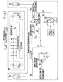
- Figure 2 shows the interface
- Figure 3 shows the circuit diagram for the interface
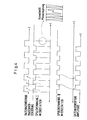
- Figures 4 to 7 show time diagrams.
- FIG. 1 shows the micro station as well as the micro unit. The following results from this block circuit.
- An oscillator 1 provides half of the oscillator frequency at the outputs Q1, Q2 via a flip-flop 2 and 3 via a positive or negative edge control. This ensures that this electromagnetic wave is a coherent (coherent) wave train (same frequency), which is retained even with spatial, contactless (wireless, contactless) transmission.
- Q2, Q3 are connected via the transistors T1, T2 to the coils S1, S2, which are coupled in a contactless manner to the coils S3, S4, which are accommodated from the movable part of the microunit 6.
- the microunit can be rotated spatially as desired, as symbolically mentioned under 7, in all cases the respective coherent signal of the oscillator 1 is received via S3, S4.
- the coherence is now disrupted by forcing Q3 a 180 degree phase shift.
- the signal Q3 is fed to the exclusive OR gate 5, the signal TM1 to be transmitted being located at the other input of this gate.
- the signal curves are shown in sheet 7.
- the TM1 signal is achieved at the exclusive OR gate that the output TM2 is phase-shifted by +/- 90 degrees compared to Q2. This phase shift is passed on to S2 via T2 and also means a phase shift in relation to T1 and 51.
- the detailed structure of the microunit 6 is shown in sheet 2 and sheet 3.
- the points A, B and C, D from sheet 2 and sheet 3 correspond to the points A, B and C, D of the microunit 6.
- the lower part of sheet 2 shows the data transmission to the micro station 4 according to the principle of the synchronous switch, the upper one Part of the data transfer from the micro station to the micro unit, based on the principle of phase shift.
- Both voltages UC, UA are tapped directly from the coils at points A and C and are fed to a phase evaluation, which here consists of a D flip-flop (D-FF1). Regardless of which signal, UA or UB, contains the phase shift, i.e.
- phase shift such as was generated in the data station on the basis of the method described above, is detected by the micro unit in the D-FF1.
- the signal relationships are shown in sheet 5. In any case, the phase shift is clearly indicated and can therefore be used for signal transmission.
- the phase positions are assigned to the logical signal UI (sheet 3) for the rest position of the microunit each time the microunit is put into operation via the level setting (sheet 2).
- the data transmission also works at times, since data is transmitted on the principle of the synchronous switch, since the phase shift remains unaffected by this.
- sheet 7 it can be seen from sheet 7 that there are favorable conditions for UE in energy transmission, since both transmission paths are available for evaluation as a power source, regardless of the spatial position of the coils and regardless of the phase shift.
- the device ensures that the transmission link can be used for the synchronous switch in parallel and simultaneously with the evaluation of the phase shift, i.e. Corresponding information can be given about the coils assigned to this route. This means that neither the signal reception from the micro station nor the signal sending. disturbed to the micro station.
- the logical assignment of the output signal (UI, sheet 3 + 5) to the corresponding phase positions takes place only after a "reset" of the microunit.
Landscapes
- Engineering & Computer Science (AREA)
- Computer Networks & Wireless Communication (AREA)
- Signal Processing (AREA)
- General Physics & Mathematics (AREA)
- Theoretical Computer Science (AREA)
- Physics & Mathematics (AREA)
- Computer Hardware Design (AREA)
- Computer Vision & Pattern Recognition (AREA)
- Artificial Intelligence (AREA)
- Microelectronics & Electronic Packaging (AREA)
- Near-Field Transmission Systems (AREA)
- Arrangements For Transmission Of Measured Signals (AREA)
- Radar Systems Or Details Thereof (AREA)
- Dc Digital Transmission (AREA)
- Digital Transmission Methods That Use Modulated Carrier Waves (AREA)
- Optical Communication System (AREA)
Abstract
- a) die Mikrostation (4), die eine Oszillatorquelle (1) zur Erzeugung von zwei Signalen aufweist, welche mit einer Phasenverschiebung von +/-90 Grad auf zwei getrennte Signalzweige (02, Q3) gegeben werden,
- b) einer der Signalzweige (Q3) erhält durch eine Schaltung (5) eine weitere Phasenverschiebung um 180 Grad, so daß die Phasenverschiebung der Signale zueinander, nach der Verschiebung um 180 Grad, wieder +/-90 Grad beträgt, wobei vor und nach dieser Phasenverscgiebung ein Phasensprung derart auftritt, daß das zweite Signal dem ersten Signal um 90 Grad vor - bzw. nacheilt,
- c) die Signal - und Energieübertragung zwischen der Mikrostation und der Mikroeinheit erfolgt über den einzelnen Signalzweigen (Q2, Q3) zugeordnete Spulen (S1, S4; S2, S3), wobei dei Signalübertragung zur Mikrostation nach dem Prinzip des Sysnchronschalters und zur Mikroeinheit nach dem Prinzip der Phasenverschiebung unabhängig voneinander erfolgt und
- d) durch eine Phasenauswertung (D-FF1), die die Phasenverschiebt ng nachweist und zur Signalübertragung heranzieht.
Description
- Die Erfindung betrifft eine Einrichtung zur berührungslosen Signal- und Energieübertragung, bestehend aus einem unbewegten Teil (Mikrostation) und einem bewegbaren Teil (Mikroeinheit).
- Der Erfindung liegt die-,Aufgabe zugrunde, Informationen und Energie berührungslos, d.h. kontaktfrei, von dem unbewegten Teil auf ein bewegbares Teil zu übertragen. Die Mikrostation, d.h. das unbewegbare Teil soll dabei auch die Leistung für die Mikroeinheit, d.h. das bewegbare Teil, zur Verfügung stellen. Wesentlich ist, daß eine derartige Einrichtung eine Reihe von Anforderungen erfüllen muß. Hierzu gehört zunächst einmal, daß die Mikroeinheit unabhängig von ihrer räumlichen Lage sowohl Daten und Energie empfangen, wie auch Daten senden können muß. Darüber hinaus muß der Datenempfang der Mikroeinheit auch während der Zeiten funktionieren, da von der Mikroeinheit zur Mikrostation Daten gesendet werden. Der Datenempfang soll schließlich unabhängig von der elektrischen Belastung der Schaltkreise auf der Mikroeinheit funktionieren und schließlich ist es wesentlich, daß Amplitudenschwankungen aufgrund der Änderung der Übertragungsstrecke oder aufgrund von Temperatureinflüssen oder sonstigen Einflüssen, keine Einwirkung auf die Signalübertragung haben.
- Der Erfindung liegt daher die Aufgabe, eine Einrichtung der eingangs genannten Art in der Weise auszubilden, daß sie die vorstehenden Anforderungen erfüllen kann, zugrunde.
- Gelöst wird diese Aufgabe erfindungsgemäß mit den Merkmalen im Kennzeichen des Patentanspruchs.
- Die Erfindung soll nachfolgend anhand der Zeichnungen erläutert werden, wobei Bild 1 das Blockschaltbild der Mikrostation und der Mikroeinheit zeigt, Figur 2 das Interface, Figur 3 den Stromlaufplan für das Interface, Figur 4 bis 7 zeigen Zeitdiagramme.
- In der Figur 1 ist, wie angegeben, die Mikrostation wie auch die Mikroeinheit dargestellt Aus dieser Blockschaltung ergibt sich folgendes.
- Von einem Oszillator 1 wird jeweils über ein Flip-Flop 2 und 3 über eine positive bzw. negative Flankensteuerung die Hälfte der Oszillatorfrequenz an den Ausgängen Ql, Q2 zur Verfügung gestellt. Derart ist gewährleistet, daß es sich bei dieser elektromagnetischen Welle um einen kohärenten (zusammenhängenden) Wellenzug (gleiche Frequenz) handelt, welche auch bei einer räumlichen, berührungslosen (drahtlos, kontaktlos) Übertragung erhalten bleibt. Q2, Q3 sind über die Transistoren Tl, T2 mit den Spulen S1, S2 verbunden, welche berührungslos mit den Spulen S3, S4 gekoppelt sind, welche aus dem beweglichen Teil der Mikroeinheit 6 untergebracht sind. Die Mikroeinheit ist räumlich beliebig drehbar, wie es unter 7 symbolisch angeführt ist, in allen Fällen wird über S3, S4 das jeweils kohärente Signal des Oszillator 1 empfangen.
- Die Kohärenz wird nun gestört, indem Q3 eine 180 Grad Phasenverschiebung aufgezwungen wird. Hierzu wird das Signal Q3 dem Exklusiv-ODER-GATTER 5 zugeführt, wobei am anderen Eingang dieses Gatters das zu übertragende Signal TM1 liegt. Die Signalverläufe sind in Blatt 7 dargestellt. Durch die jeweilige HIGH- oder LOW-Stellung des TM1-Signals wird am Exklusiv-ODER-GATTER erreicht, daß der Ausgang TM2 um +/- 90 Grad gegenüber Q2 phasenverschoben wird. Diese Phasenverschiebung wird über T2 an S2 weitergegeben und bedeutet auch eine Phasenverschiebung in Relation zu Tl und 51.
- Der nähere Aufbau der Mikroeinheit 6 ist in Blatt 2 und und Blatt 3 gezeichnet. Die Punkte A,B und C,D aus Blatt 2 und Blatt 3 entsprechen den Punkten A,B und C,D der Mikroeinheit 6. Im unteren Teil von Blatt 2 ist die Datenübertragung zur Mikrostation 4 nach dem Prinzip des Synchronschalters dargestellt, im oberen Teil die Datenübertragung von der Mikrostation zur Mikroeinheit, nach dem Prinzip der Phasenverchiebung. Beide Spannungen UC, UA werden direkt von den Spulen an den Punkten A bzw. C abgegriffen und werden einer Phasenauswertung zugeführt, welche hier aus einem D-Flip-Flop (D-FF1) besteht. Unabhängig welches Signal, UA oder UB, den Phasensprung enthält, d.h. welche räumliche Zuordnung der Spulen der Mikrostation zur Mikroeinheit vorlag, wird eine Phasenverschiebung, wie sie aufgrund des oben geschilderten Verfahrens in der Datenstation erzeugt wurde, auf Seiten der Mikroeinheit im D-FF1 nachgewiesen. Die Signalverhältnisse sind in Blatt 5 dargestellt. Die Phasenverschiebung wird in jedem Falle eindeutig indiziert und kann somit zur Signalübertragung herangezogen werden. Die Zuordnung der Phasenlagen zu dem logischen Signal UI (Blatt 3) für die Ruhestellung der Mikroeinheit erfolgt jedesmal nach Inbetriebnahme der Mikroeinheit über die Pegelfestlegung (Blatt 2).
- Wie aus Blatt 4 ersichtlich, funktioniert die Datenübertragung auch zu Zeitpunkten, da nach dem Prinzip des Synchronschalters Daten übertragen werden, da die Phasenverschiebung hiervon unberührt bleibt. Außerdem ist aus Blatt 7 ersichtlich, daß günstige Verhältnisse für UE bei der Energieübertragung vorliegen, da unabhängig von der räumlichen Lage der Spulen und unabhängig von der Phasenverschiebung beide Übertragungswege zur Auswertung als Leistungsquelle zur Verfügung stehen.
- Wie sich aus den vorstehenden Ausführungen ergibt, gewährleistet die erfindungsgemäße Einrichtung, daß parallel und gleichzeitig zu der Auswertung der Phasenverschiebung, die Übertragungsstrecke für den Synchronschalter benutzbar ist, d.h. entsprechende Informationen über die dieser Strecke zugeordneten Spulen gegeben werden können. Damit wird weder der Signalempfang von der Mikrostation noch das Signalsen-. den zur Mikrostation gestört. Je nach Anordnung der Spulen zueinander, die auch in sich gedreht sein dürfen, erfolgt erst nach einem "Reset" der Mikroeinheit die logische Zuordnung des Ausgangssignales (UI, Blatt 3 + 5) zu den entsprechenden Phasenlagen.
Claims (1)
Priority Applications (1)
| Application Number | Priority Date | Filing Date | Title |
|---|---|---|---|
| AT85730170T ATE62573T1 (de) | 1984-12-21 | 1985-12-20 | Einrichtung zur beruehrungslosen signal- und energieuebertragung. |
Applications Claiming Priority (2)
| Application Number | Priority Date | Filing Date | Title |
|---|---|---|---|
| DE19843447560 DE3447560A1 (de) | 1984-12-21 | 1984-12-21 | Einrichtung zur beruehrungslosen signal- und energieuebertragung |
| DE3447560 | 1984-12-21 |
Publications (3)
| Publication Number | Publication Date |
|---|---|
| EP0185610A2 true EP0185610A2 (de) | 1986-06-25 |
| EP0185610A3 EP0185610A3 (en) | 1988-03-09 |
| EP0185610B1 EP0185610B1 (de) | 1991-04-10 |
Family
ID=6253986
Family Applications (1)
| Application Number | Title | Priority Date | Filing Date |
|---|---|---|---|
| EP85730170A Expired - Lifetime EP0185610B1 (de) | 1984-12-21 | 1985-12-20 | Einrichtung zur berührungslosen Signal- und Energieübertragung |
Country Status (5)
| Country | Link |
|---|---|
| US (1) | US4697183A (de) |
| EP (1) | EP0185610B1 (de) |
| JP (1) | JPH0710055B2 (de) |
| AT (1) | ATE62573T1 (de) |
| DE (2) | DE3447560A1 (de) |
Cited By (10)
| Publication number | Priority date | Publication date | Assignee | Title |
|---|---|---|---|---|
| GB2204972A (en) * | 1987-05-19 | 1988-11-23 | Gen Electric Co Plc | Vehicle data storage system |
| EP0334804A3 (en) * | 1988-03-25 | 1990-05-16 | Angewandte Digital Elektronik Gmbh | Resonant circuit with stabilized phase coupling |
| FR2646035A1 (fr) * | 1989-04-15 | 1990-10-19 | Daimler Benz Ag | Procede pour une transmission synchrone de donnees, notamment a partir de parties fixes ou mobiles dans des vehicules automobiles |
| WO1991010206A1 (en) * | 1989-12-20 | 1991-07-11 | Cryptag Limited | Transmission system |
| DE4018814A1 (de) * | 1990-06-12 | 1992-01-02 | Fraunhofer Ges Forschung | Verfahren und system zum uebertragen von energie und daten |
| EP0509125A1 (de) * | 1991-04-19 | 1992-10-21 | Siemens Aktiengesellschaft | Einrichtung zur berührungslosen Daten- und Energieübertragung sowie Verfahren zum Betrieb einer solchen |
| GB2262634A (en) * | 1991-12-18 | 1993-06-23 | Apple Computer | Inductive power and signal connection. |
| NL9301697A (nl) * | 1993-10-01 | 1995-05-01 | Nedap Nv | Fasedemodulator voor contactloze chipkaarten. |
| DE19523901A1 (de) * | 1995-06-30 | 1997-01-09 | Bosch Gmbh Robert | Abnehmbares Frontteil für ein Autoradio |
| EP0704814A3 (de) * | 1994-09-30 | 1997-06-04 | Toshiba Kk | Magnetisches Kupplungstreiberschaltungssystem |
Families Citing this family (36)
| Publication number | Priority date | Publication date | Assignee | Title |
|---|---|---|---|---|
| DE3614477A1 (de) * | 1986-04-29 | 1987-11-05 | Angewandte Digital Elektronik | Vorrichtung zur bidirektionalen datenuebertragung |
| BE1000709A4 (nl) * | 1987-07-01 | 1989-03-14 | Elek Citeit Voor Goederenbehan | Inrichting voor de transmissie van gegevens. |
| DE3824972A1 (de) * | 1988-07-22 | 1989-01-12 | Roland Hiering | Weihnachtsbaum-, dekorations-, kunstwerk- und schmuckbeleuchtung |
| ATE135835T1 (de) * | 1990-07-16 | 1996-04-15 | Siemens Ag | Einrichtung zur berührungslosen daten- und energieübertragung sowie verwendung einer solchen |
| DE4031692C1 (en) * | 1990-10-02 | 1992-06-04 | Angewandte Digital Elektronik Gmbh, 2051 Brunstorf, De | Electronic key circuit in contactless chip=card - forms interface working with prim. electronic integrated circuit using interactive coils with ferrite cores buried in substrate |
| DE4038970A1 (de) * | 1990-12-06 | 1992-06-11 | Schlafhorst & Co W | Verfahren und einrichtung zur bidirektionalen datenuebermittlung zwischen einer textilmaschine und einem textilen produkt |
| US5495241A (en) * | 1991-01-25 | 1996-02-27 | Siemens Aktiengesellschaft | Method for reducing power loss in devices for contactless data and energy transfer, and apparatus for performing the method |
| US5450076A (en) * | 1991-01-25 | 1995-09-12 | Siemens Aktiengesellschaft | Method for reducing power loss in devices for contactless data and energy transmission, and apparatus for performing the method |
| DE59207303D1 (de) * | 1991-02-28 | 1996-11-14 | Siemens Ag | Verfahren zur Datenübertragung von einer stationären Einheit zu einer einen Datenspeicher und einen zugehörigen Schutzspeicher aufweisenden beweglichen Einheit |
| DE4107311C2 (de) * | 1991-03-07 | 1996-02-08 | Telefunken Microelectron | Verfahren zur drahtlosen Übertragung von Daten auf einen Datenträger |
| DE4115065A1 (de) * | 1991-05-08 | 1992-11-12 | Angewandte Digital Elektronik | Stromfluss kontroll-schaltung |
| DE4119553C1 (de) * | 1991-06-13 | 1992-10-29 | Siemens Ag, 8000 Muenchen, De | |
| US5325046A (en) * | 1991-12-18 | 1994-06-28 | Apple Computer, Inc. | Inductive wireless data connection |
| DE4202998A1 (de) * | 1992-02-03 | 1993-08-05 | Angewandte Digital Elektronik | Plasikkarte mit elektronischer magnetstreifensimulation |
| US5376778A (en) * | 1992-02-26 | 1994-12-27 | Angewandte Digital Electronik Gmbh | Contact-free chip card for remote transmission |
| DE4215955C1 (de) * | 1992-05-14 | 1993-12-09 | Siemens Ag | Informationsübertragungssystem, bestehend aus einer Schreib/Leseeinheit und einer tragbaren Datenträgeranordnung |
| DE4215957C2 (de) * | 1992-05-14 | 1994-05-19 | Siemens Ag | Einrichtung zur Informationsübertragung mit einem stationären Teil und einer tragbaren Datenträgeranordnung |
| DE4215956C2 (de) * | 1992-05-14 | 1994-04-28 | Siemens Ag | Informationsübertragungssystem, bestehend aus einer Schreib/Leseeinheit und einer tragbaren Datenträgeranordnung |
| DE4230148C2 (de) * | 1992-09-09 | 1994-08-25 | Angewandte Digital Elektronik | Schaltungsanordnung zum Nachweis einer Unterbrechung der elektrischen Verbindung von kontaktfrei arbeitenden Chipkarten zu ihrem Schreib/Lesegerät |
| DE4240238C2 (de) * | 1992-11-30 | 1995-01-05 | Angewandte Digital Elektronik | Einrichtung zur berührungslosen Energie- und Datenübertragung für Einspulen- und Zweispulensysteme |
| DE4306378A1 (de) * | 1993-03-02 | 1994-09-08 | Schlafhorst & Co W | Verfahren und Vorrichtung zur Positionserfassung eines einen Kops tragenden Kopsträgers |
| DE4327334C1 (de) * | 1993-08-15 | 1995-01-12 | Angewandte Digital Elektronik | Chipkarte |
| US6167094A (en) * | 1996-10-15 | 2000-12-26 | Siemens Aktiengesellschaft | Data transmission circuit having a station and a response circuit |
| DE19642568A1 (de) * | 1996-10-15 | 1998-04-23 | Siemens Ag | Datenübertragungsschaltung mit einer Station und mit einer Antwortschaltung |
| DE19731035B4 (de) * | 1997-07-18 | 2004-09-02 | Anatoli Stobbe | Verfahren zur Datenübertragung zwischen einem Schreib-Lesegerät und einem Transponder |
| DE19744782C2 (de) * | 1997-10-10 | 1999-09-23 | Anatoli Stobbe | Verfahren und Vorrichtung zur Datenübertragung zwischen einem Schreib-Lesegerät und einem Transponder |
| US5995874A (en) * | 1998-02-09 | 1999-11-30 | Dew Engineering And Development Limited | Transcutaneous energy transfer device |
| US6058330A (en) * | 1998-03-06 | 2000-05-02 | Dew Engineering And Development Limited | Transcutaneous energy transfer device |
| DE10234893A1 (de) | 2002-07-26 | 2004-02-12 | Sipra Patententwicklungs- Und Beteiligungsgesellschaft Mbh | Vorrichtung mit einem stationären und einem bewegbaren Bauteil und einer Einrichtung zur gleichzeitigen Übertragung von elektrischer Energie und Information zwischen diesen Bauteilen |
| GB2410397B (en) * | 2004-01-21 | 2007-11-14 | Airspan Networks Inc | A subscriber terminal for a telecommunications system |
| US7215133B2 (en) * | 2004-01-30 | 2007-05-08 | International Business Machines Corporation | Contactless circuit testing for adaptive wafer processing |
| US20110218622A1 (en) * | 2010-03-05 | 2011-09-08 | Micardia Corporation | Induction activation of adjustable annuloplasty rings and other implantable devices |
| EP2932901B1 (de) * | 2014-04-16 | 2016-10-26 | Schleifring und Apparatebau GmbH | Drehverbindung für mehrkanalige Hochgeschwindigkeits-Datenübertragung |
| US11693966B2 (en) * | 2019-08-14 | 2023-07-04 | Nxp B.V. | System and method for triggering and detecting hardware trojans |
| WO2021155176A1 (en) | 2020-01-30 | 2021-08-05 | University Of Rhode Island Board Of Trustees | Bus authentication and anti-probing architecture |
| US12306944B1 (en) * | 2020-12-29 | 2025-05-20 | University Of Rhode Island Board Of Trustees | Method and apparatus for runtime detection of bus probing/tampering in computer systems |
Family Cites Families (10)
| Publication number | Priority date | Publication date | Assignee | Title |
|---|---|---|---|---|
| SE317013B (de) * | 1968-10-31 | 1969-11-03 | Aga Ab | |
| US3713124A (en) * | 1970-07-13 | 1973-01-23 | Beckman Instruments Inc | Temperature telemetering apparatus |
| CH563046A5 (en) * | 1971-09-14 | 1975-06-13 | Autopack Ltd | Data transmission device - transmits data between two objects which are displaced with respect to each other |
| US3803567A (en) * | 1973-02-23 | 1974-04-09 | Chandler Evans Inc | Resolver to pulse width converter |
| SE396249B (sv) * | 1976-01-13 | 1977-09-12 | Asea Ab | Beroringsfri signaloverforing |
| US4358722A (en) * | 1977-08-17 | 1982-11-09 | Kabushiki Kaisha Yaskawa Denki Seisakusho | Speed detector using resolver |
| DE2949075C2 (de) * | 1979-12-06 | 1982-10-28 | Honeywell Gmbh, 6050 Offenbach | Anordnung zur kontaktlosen Temperaturmessung an einem drehbaren Maschinenteil |
| DE3101636A1 (de) * | 1981-01-20 | 1982-08-26 | Siemens AG, 1000 Berlin und 8000 München | Einrichtung zur drahtlosen informationsuebertragung |
| US4511896A (en) * | 1982-07-30 | 1985-04-16 | The United States Of America As Represented By The Secretary Of The Army | Remote sensor system with bi-directional monitoring and control of operation |
| JPS5954917A (ja) * | 1982-09-24 | 1984-03-29 | Toshiba Corp | デイジタル移動検出装置 |
-
1984
- 1984-12-21 DE DE19843447560 patent/DE3447560A1/de active Granted
-
1985
- 1985-12-19 US US06/810,558 patent/US4697183A/en not_active Expired - Lifetime
- 1985-12-20 DE DE8585730170T patent/DE3582483D1/de not_active Expired - Fee Related
- 1985-12-20 JP JP60285919A patent/JPH0710055B2/ja not_active Expired - Lifetime
- 1985-12-20 EP EP85730170A patent/EP0185610B1/de not_active Expired - Lifetime
- 1985-12-20 AT AT85730170T patent/ATE62573T1/de not_active IP Right Cessation
Cited By (13)
| Publication number | Priority date | Publication date | Assignee | Title |
|---|---|---|---|---|
| GB2204972A (en) * | 1987-05-19 | 1988-11-23 | Gen Electric Co Plc | Vehicle data storage system |
| EP0334804A3 (en) * | 1988-03-25 | 1990-05-16 | Angewandte Digital Elektronik Gmbh | Resonant circuit with stabilized phase coupling |
| FR2646035A1 (fr) * | 1989-04-15 | 1990-10-19 | Daimler Benz Ag | Procede pour une transmission synchrone de donnees, notamment a partir de parties fixes ou mobiles dans des vehicules automobiles |
| WO1991010206A1 (en) * | 1989-12-20 | 1991-07-11 | Cryptag Limited | Transmission system |
| DE4018814A1 (de) * | 1990-06-12 | 1992-01-02 | Fraunhofer Ges Forschung | Verfahren und system zum uebertragen von energie und daten |
| US5329274A (en) * | 1991-04-19 | 1994-07-12 | Siemens Aktiengesellschaft | Apparatus for contactless data and energy transmission and method for operating such an apparatus |
| EP0509125A1 (de) * | 1991-04-19 | 1992-10-21 | Siemens Aktiengesellschaft | Einrichtung zur berührungslosen Daten- und Energieübertragung sowie Verfahren zum Betrieb einer solchen |
| GB2262634A (en) * | 1991-12-18 | 1993-06-23 | Apple Computer | Inductive power and signal connection. |
| GB2262634B (en) * | 1991-12-18 | 1995-07-12 | Apple Computer | Power connection scheme |
| NL9301697A (nl) * | 1993-10-01 | 1995-05-01 | Nedap Nv | Fasedemodulator voor contactloze chipkaarten. |
| EP0651539A1 (de) * | 1993-10-01 | 1995-05-03 | N.V. Nederlandsche Apparatenfabriek NEDAP | Kontaktloses Informationsübertragungssystem mit Phasenmodulation |
| EP0704814A3 (de) * | 1994-09-30 | 1997-06-04 | Toshiba Kk | Magnetisches Kupplungstreiberschaltungssystem |
| DE19523901A1 (de) * | 1995-06-30 | 1997-01-09 | Bosch Gmbh Robert | Abnehmbares Frontteil für ein Autoradio |
Also Published As
| Publication number | Publication date |
|---|---|
| JPH0710055B2 (ja) | 1995-02-01 |
| EP0185610B1 (de) | 1991-04-10 |
| DE3447560A1 (de) | 1986-07-10 |
| EP0185610A3 (en) | 1988-03-09 |
| ATE62573T1 (de) | 1991-04-15 |
| US4697183A (en) | 1987-09-29 |
| DE3582483D1 (de) | 1991-05-16 |
| DE3447560C2 (de) | 1988-08-25 |
| JPS61203738A (ja) | 1986-09-09 |
Similar Documents
| Publication | Publication Date | Title |
|---|---|---|
| EP0185610B1 (de) | Einrichtung zur berührungslosen Signal- und Energieübertragung | |
| EP0466949B1 (de) | Einrichtung zur berührungslosen Daten- und Energieübertragung sowie Verwendung einer solchen | |
| DE2918857C2 (de) | ||
| DE2933473A1 (de) | Transformatoranordnung zur einkopplung eines nachrichtensignals in eine dreiphasen-netzleitung | |
| EP0510220A1 (de) | Einrichtung zur berührungslosen Daten- und Energieübertragung | |
| DE2339550A1 (de) | Automatisches fahrzeugleitsystem | |
| CH661384A5 (de) | Anordnung zur steuerung einer uebertragungsanlage fuer hochgespannten gleichstrom. | |
| EP0496024B1 (de) | Verfahren zur Reduzierung der Verlustleistung bei Einrichtungen zur berührungslosen Daten-und Energieübertragung sowie Anordnung zur Durchführung des Verfahrens | |
| DE69130330T2 (de) | Oszillatoreinheit mit verbesserter frequenzstabilität | |
| DE2134783B2 (de) | Verfahren zur Ermittlung von Fehlern in den mit Regeneratoren versehenen Zwischenstellen eines mit Pulscodemodulation arbeitenden Übertragungssystems | |
| EP0023605A1 (de) | Funksystem | |
| EP0496023B1 (de) | Verfahren zur Reduzierung der Verlustleistung bei Einrichtungen zur berührungslosen Daten- und Energieübertragung sowie Anordnung zur Durchführung des Verfahrens | |
| DE2001942C3 (de) | ||
| EP0415111B1 (de) | Betriebs-Ersatz-Taktversorgung für digitale Systeme | |
| DE102025118773A1 (de) | Ausbreitungsverzögerungskompensation in daisy-chain-topologien | |
| DE2206203A1 (de) | Einrichtung zur uebertragung von elektrischen signalen | |
| DE2525631C2 (de) | Verfahren und Schaltungsanordnung zur Fernspeisung elektronischer Nebenuhren | |
| DE3347609A1 (de) | Kommunikations- und ueberwachungssystem fuer verkehrstechnik | |
| DE3741749A1 (de) | Kompensationsleistungssystem fuer eine spannungsverteileranlage | |
| DE68904896T2 (de) | Anordnung zur drahtlosen uebertragung von empfangenen signalen ueber einen seriellen datenbus mit zwei leitern. | |
| DE2443869A1 (de) | Digitaldatenuebertragungsanlage | |
| EP0209189A2 (de) | Anordnung zur Synchronisation der pulsbreitenmodulierten Schalttakte mehrerer getakteter Gleichspannungswandler | |
| EP0081835A1 (de) | Regenerator für ein digitales Nachrichtensystem | |
| DE3315956A1 (de) | Bidirektionales serielles uebertragungssystem fuer digitale informationen | |
| DE2529574C2 (de) | Schaltungsanordnung zur Verbesserung der Qualität einer Diversity-Datenübertragung |
Legal Events
| Date | Code | Title | Description |
|---|---|---|---|
| PUAI | Public reference made under article 153(3) epc to a published international application that has entered the european phase |
Free format text: ORIGINAL CODE: 0009012 |
|
| AK | Designated contracting states |
Kind code of ref document: A2 Designated state(s): AT CH DE FR GB IT LI NL SE |
|
| PUAL | Search report despatched |
Free format text: ORIGINAL CODE: 0009013 |
|
| AK | Designated contracting states |
Kind code of ref document: A3 Designated state(s): AT CH DE FR GB IT LI NL SE |
|
| 17P | Request for examination filed |
Effective date: 19880427 |
|
| 17Q | First examination report despatched |
Effective date: 19891023 |
|
| GRAA | (expected) grant |
Free format text: ORIGINAL CODE: 0009210 |
|
| AK | Designated contracting states |
Kind code of ref document: B1 Designated state(s): AT CH DE FR GB IT LI NL SE |
|
| PG25 | Lapsed in a contracting state [announced via postgrant information from national office to epo] |
Ref country code: SE Effective date: 19910410 |
|
| REF | Corresponds to: |
Ref document number: 62573 Country of ref document: AT Date of ref document: 19910415 Kind code of ref document: T |
|
| REF | Corresponds to: |
Ref document number: 3582483 Country of ref document: DE Date of ref document: 19910516 |
|
| ET | Fr: translation filed | ||
| ITF | It: translation for a ep patent filed | ||
| GBT | Gb: translation of ep patent filed (gb section 77(6)(a)/1977) | ||
| PG25 | Lapsed in a contracting state [announced via postgrant information from national office to epo] |
Ref country code: AT Effective date: 19911231 |
|
| PLBE | No opposition filed within time limit |
Free format text: ORIGINAL CODE: 0009261 |
|
| STAA | Information on the status of an ep patent application or granted ep patent |
Free format text: STATUS: NO OPPOSITION FILED WITHIN TIME LIMIT |
|
| 26N | No opposition filed | ||
| PGFP | Annual fee paid to national office [announced via postgrant information from national office to epo] |
Ref country code: CH Payment date: 20000301 Year of fee payment: 15 |
|
| PGFP | Annual fee paid to national office [announced via postgrant information from national office to epo] |
Ref country code: DE Payment date: 20000728 Year of fee payment: 15 |
|
| PGFP | Annual fee paid to national office [announced via postgrant information from national office to epo] |
Ref country code: GB Payment date: 20001214 Year of fee payment: 16 |
|
| PGFP | Annual fee paid to national office [announced via postgrant information from national office to epo] |
Ref country code: FR Payment date: 20001221 Year of fee payment: 16 |
|
| PG25 | Lapsed in a contracting state [announced via postgrant information from national office to epo] |
Ref country code: LI Free format text: LAPSE BECAUSE OF NON-PAYMENT OF DUE FEES Effective date: 20001231 Ref country code: DE Free format text: LAPSE BECAUSE OF NON-PAYMENT OF DUE FEES Effective date: 20001231 Ref country code: CH Free format text: LAPSE BECAUSE OF NON-PAYMENT OF DUE FEES Effective date: 20001231 |
|
| PGFP | Annual fee paid to national office [announced via postgrant information from national office to epo] |
Ref country code: NL Payment date: 20001231 Year of fee payment: 16 |
|
| REG | Reference to a national code |
Ref country code: CH Ref legal event code: PL |
|
| PG25 | Lapsed in a contracting state [announced via postgrant information from national office to epo] |
Ref country code: GB Free format text: LAPSE BECAUSE OF NON-PAYMENT OF DUE FEES Effective date: 20011220 |
|
| REG | Reference to a national code |
Ref country code: GB Ref legal event code: IF02 |
|
| PG25 | Lapsed in a contracting state [announced via postgrant information from national office to epo] |
Ref country code: NL Free format text: LAPSE BECAUSE OF NON-PAYMENT OF DUE FEES Effective date: 20020701 |
|
| GBPC | Gb: european patent ceased through non-payment of renewal fee |
Effective date: 20011220 |
|
| PG25 | Lapsed in a contracting state [announced via postgrant information from national office to epo] |
Ref country code: FR Free format text: LAPSE BECAUSE OF NON-PAYMENT OF DUE FEES Effective date: 20020830 |
|
| NLV4 | Nl: lapsed or anulled due to non-payment of the annual fee |
Effective date: 20020701 |
|
| REG | Reference to a national code |
Ref country code: FR Ref legal event code: ST |